Page is loading ...

12/16/11
800-810-WIRE (9473) • www.sargentlock.com • A6946C
1
Copyright © 2011 Sargent Manufacturing Company, an ASSA ABLOY Group company. All rights reserved.
Reproductions in whole or in part without express written permission of Sargent Manufacturing Company is prohibited.
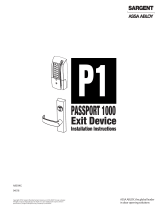
4299 WALL SWITCH
INSTALLATION INSTRUCTIONS
INSTALLATION INSTRUCTIONS
Face Plate Stainless Steel; 4-1/2” x 2-3/4”
Push Button Illuminated Green “EXIT”
Contact Rating 10A @ 125VAC
6A @ 30VDC
Switch Type Normally Open (N.O.) Momentary contact (SPDT)
GENERAL INFORMATION
SPECIFICATIONS
1
2
3
SARGENT Model 4299 Wall Switch is a momentary contact switch.
EXIT
A. Important
1. CAUTION: Disconnect all power before beginning installation to prevent electrical shock
and equipment damage.
2. Installer must be a trained and experienced service person.
3. All wiring must comply with applicable local electrical codes, ordinances and regulations.
4-1/2”
2-3/4”

800-810-WIRE (9473) • www.sargentlock.com • A6946C
12/16/11
Copyright © 2011 Sargent Manufacturing Company, an ASSA ABLOY Group company. All rights reserved.
Reproductions in whole or in part without express written permission of Sargent Manufacturing Company is prohibited.
2
4299 WALL SWITCH
INSTALLATION INSTRUCTIONS
INSTALLATION (continued)
B. Installation
Reach Ranges
• If a clear floor space allows only a forward approach, the maximum high forward reach shall be 48”.
• The minimum low forward reach shall be 15”.
If the high forward reach is over an obstruction, the following conditions hall be met:
• Knee space below obstruction shall equal or exceed reach length required above the obstruction.
• If the obstruction is less than 20” deep, the maximum high forward reach shall be 48”.
• If the obstruction is 20-25” deep, the maximum high forward reach shall be 44”.
• If a clear floor space allows a parallel approach, the maximum high side reach shall be 54”.
• The minimum low side reach shall be 9”.
If the high side reach is over an obstruction, the following conditions shall be met:
• Obstruction shall be 34” maximum in height, 24” in depth, maximum high side reach shall be 46”.
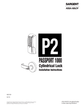
Typical Wiring for Basic System
Pressing the button will momentarily release the lock. The lock will
remain unlocked as long as the push button is held depressed.
CONTROL SWITCH 4299
ELECTRIC LOCK,
EXIT DEVICE, or
ELECTROMAGNETIC LOCK
( - )
( + )
24VDC REG.
POWER
SUPPLY
1. Mount a single-gang outlet box to stud or other rigid structure.
2. To meet ADA requirements, the following must be observed:
/