Page is loading ...

FCC ID: U4A-PRXTRMH1 IC ID: 6982A-PRXTRMH1 Report No. M060902_Cert_Rx
EMC Technologies Pty Ltd – 176 Harrick Road, Keilor Park VIC 3042 Australia
www.emctech.com.au
EMC Technologies Report Number: M060902_Cert_Rx
APPENDIX G
USER MANUAL

Installation Instructions For
Harmony Series
H1 Mortise Lock
A7877A
03/07
© SARGENT Manufacturing Company 2007

Table of Contents
Warning
General Description.....................................................1
Specifications............................................................1
Features ..................................................................1
Parts Breakdown .......................................................2-3
Installation Instructions ..............................................4-11
Operational Check......................................................12
Page
1
2
3
4
5
6
7
This device complies with Part 15 of the FCC Rules. Operation is subject to the following two conditions: (1) this
device may not cause harmful interference, and (2) this device must accept any interference received, including
interference that may cause undesired operation.
Note: This equipment has been tested and found to comply with the limits for a Class B digital device, pursuant to
Part 15 of the FCC Rules. These limits are designed to provide reasonable protection against harmful interference in
a residential installation. This equipment generates, uses and can radiate radio frequency energy and if not installed
and used in accordance with the instructions, may cause harmful interference to radio communications. However,
there is no guarantee that the interference will not occur in a particular installation. If this equipment does cause
harmful interference to radio or television reception, which can be determined by turning the equipment off and on,
the user is encouraged to try to correct the interference by one or more of the following measures:
•
Reorient or r
elocate the r
eceiving antenna
• Increase the separation between the equipment and receiver
• Connect the equipment into an outlet on a circuit different from that to which the receiver is connected
•
Consult the dealer or an experienced TV technician for help
This Class B digital apparatus complies with Canadian ICES-003.
Cet appar
eil numérique de la classe B est confor
me avec la norme NMB-003 du Canada.
Warning
1
Warning: Changes or modifications to this unit not expressly approved by the party
responsible for compliance could void the user's authority to operate the equipment.

For installation assistance, contact SARGENT at 800-810-WIRE (9473)
A7877A © SARGENT Manufacturing Company 2007
1
Harmony Series H1 Mortise Lock
The SARGENT Harmony Series H1 Mortise Lock is designed to interface with an existing weigand access
control system.
General Description
2
Specifications
• Latch - Stainless steel 3⁄4" projection one-piece
• Deadbolt - One-piece hardened stainless steel
• Guardbolt - Stainless steel, non-handed
• Handed - Easily field reversible without
opening case
• Case - 12 gauge heavy duty wrought steel
• Outside lever controlled by any prox credentials
• Inside lever provides REX signal and retracts latch
and deadbolt
• Locks furnished for 1-3/4" doors. Can be
furnished for other door sizes upon request.
Consult factory
• U.L. Listed (3 hr.)
Features
• Complete monitoring of door from locks
•
Wires directly to Access Control System
• 12 or 24 VDC Fail Safe/Fail Secure
• HID 125khz proximity credentials
•
All HID Bit formats
3
4
Harmony Series
H1
Wiegand
Access Control
System
(By Others)
Power
12VDC or 24VDC

For installation assistance, contact SARGENT at 800-810-WIRE (9473)
© SARGENT Manufacturing Company 2007 A7877A
2
1
2
3
4
5
6
7
8
9
10
11
10
12
13
14
8
6
5
1
5
16/17
18/19
2
0
21
22
23
24/25/26
27
28
29
29
28
27
3
0
31
32
33
34
Harmony Series H1 Mortise Lock
5
Parts Breakdown

For installation assistance, contact SARGENT at 800-810-WIRE (9473)
A7877A © SARGENT Manufacturing Company 2007
3
Harmony Series H1 Mortise Lock
5
Parts Breakdown (Continued)
ITEM PART No. DESCRIPTION REQ’D
1 52-5188 Outside Escutcheon Reader Assembly w/Cylinder 1
1 52-5189 Outside Escutcheon Reader Assembly w/o Cylinder 1
2 52-5184 Inside Escutcheon Assembly w/Turn 1
2 52-5185 Inside Escutcheon Assembly w/o Turn 1
3 52-0798 Mounting Plate - Mortise 1
4
Reference Harmony Series catalog for available lever handles
15
5 Reference Harmony Series catalog for available Rose styles 2
6 82-0347 Inside/Outside Spring 2
7 82-0614 Spindle Anchor 1
8 82-0368 Inside/Outside Spindle 2
9 81-0723 Mounting Post 2
10 01-0079 Washer 2
11 82-3082 Plate Assembly 1
12
82-0184 Cap Nut 1
13 82-3088 Inside Spindle Adapter and Plate Assembly 1
14 01-1495 Screw #8-32 x 1/2" 2
16 Lock Body Assembly w/Dead Bolt - 82280-82283 12/24V Functions 1
17 Lock Body Assembly w/o Dead Bolt - 82270-82273 12/24V Functions 1
18 82-0081 Face Plate w/o Dead Bolt 1
19 82-0084 Face Plate w/ Dead Bolt 1
20 77-1467 Through-bolts #8-32 x 2" Phillips Flat Head Screw 2
21 01-1218 Wood Screw #6 x 3/8" Phillips Flat Head 4
22 01-4577 Escutcheon Screw #8-32 x 5/8" Phillips Flat Head 1
23 01-1028 Escutcheon Screw #8-32 x 1/4" Phillips Flat Head 1
24 01-1472 Lever Handle Screw, A, E and F Lever 1
25 01-1174 Lever Handle Screw, B, J, L, P and W Lever 1
26 82-0995 Lever Handle Screw - Studio Collection 1
27 01-2299 Lock Body Screw - Wood Door #12 x 1 1/4" 2
28 01-1019 Lock Body Screw - Metal Door #12-24 x 1/2" 2
29 01-1028 Face Plate Screw Machine - #8-32 x 1/4" 2
30 52-0796 Gasket Harmony Outside - Mortise 1
31
52-0795
Gasket Harmony Inside - Mortise
1
32 82-4576 Adapter and Plate Assembly (DL) 1
33 82-0691 Bushing Outside (DL) 1
34
82-4577
Inside
Adapter Plate and Bushing
Assembly (DL)
1

For installation assistance, contact SARGENT at 800-810-WIRE (9473)
© SARGENT Manufacturing Company 2007 A7877A
4
Harmony Series H1 Mortise Lock
Installation Instructions
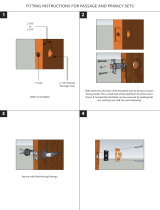
6
Verify Hand and Bevel of Door
Thru-bolt hole
2 places
Outside cylinder hole
76/78 functions only
Lever handle hole
Pre-drilled and/or
Tapped holes 2 places
Outside
of door
Hole for cable from
Reader to controller board
Inside cylinder hole
Thumb turn hole
Lever handle hole
Mortise area
Inside
of door
Pre-drilled and/or
Tapped holes 2 places
Raceway for
network/power cable
(ELynx) 12 Conductor
Before Starting
Wood door - A7879 template ships with product. For replacement
template, contact SARGENT (4541 for raceway, wood and metal door)
Metal door - 4590 for Locks With Deadbolt
Step #1 – Door Preparation

For installation assistance, contact SARGENT at 800-810-WIRE (9473)
A7877A © SARGENT Manufacturing Company 2007
5
Harmony Series H1 Mortise Lock
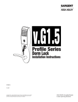
Step #2 – How to Reverse Lock Hand
Connector
Red color
locking piece
indicates locked side
Note: Beveled surface of latch must face strike.
The deadlatch is self adjusting. To change hand of latch:
1. Insert screwdriver blade into the spade shaped slot
2. Rotate screwdriver 90º to push latch out until back of latch
clears lock front. Then rotate latch 180º.
Latch will then re-enter lockbody.
(Note: Latch can not be unscrewed)
Note: Red surface of locking piece must face secure side of door.
T
o rotate locking piece:
1. Position lockbody with red surface of locking piece visible
2. Insert blade type screwdriver into locking piece slot to rotate
l
ocking piece
3. Push locking piece toward back of lock body and rotate 180°
until RED surface shows on opposite side
4. Red indicates locked (outside) side.
5. Wire harness MUST exit thru non-cylinder side.
Right hand
shown
Triangular
slot
Locking
guide slot
Rotate
Push in
Red color
locking piece
indicates locked side
End Cap
End
cap
Connector
L
Outside of
door
Connector
and wires
Latchbolt
Connector
and wires
Latchbolt
Front
Deadbolt
Dead latch
End
cap
Outside of
door
Right hand
shown
Triangular
slot
Locking
guide slot
Rotate
Push in
Red color
locking piece
indicates locked side
End Cap
End
cap
Connector
Latchbolt
Outside of
door
Front
Deadbolt
Dead latch
Connector
and wires
Latchbolt

For installation assistance, contact SARGENT at 800-810-WIRE (9473)
© SARGENT Manufacturing Company 2007 A7877A
6
Harmony Series H1 Mortise Lock
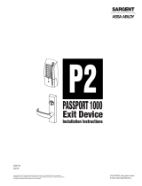
(2)#12-24 x 1/2" long
f
lat head screws
for metal doors.
flat head wood screws
for wood doors.
Must feed
connectors and
wires thru
non-cylinder
side
Inside of
door
(2)#12 x 1=1/4" long
Step #3 – Lockbody Installation
Step #4 – Inside Mounting
Plate Installation
Wires and connector go into the mortised
a
rea and out of the inside cylinder hole
Inside of
door
Self tapping screws
#8 x 1/2" long for
wood and metal doors
4 required
1/8" Dia hole
4 required
1. Secure the mounting plate with (4) self tapping
screws (#8 x 1/2").

For installation assistance, contact SARGENT at 800-810-WIRE (9473)
A7877A © SARGENT Manufacturing Company 2007
7
Profile Series H1 Mortise Lock
1. Securely tighten lockbody screws on the edge of the door and
then securely tighten the thru bolt screws.
2. Connect P3 (2 Pin Connector) from lock body to J3 on Interior
Escutcheon PCB Assembly.
3.
Connect P4 (5 Pin Connector) from lock body to J4 on Interior
Escutcheon PCB Assembly.
4. Connect P5 (7 Pin Connector) from Reader board to J5 on
Interior Escutcheon PCB Assembly
.
5. Connect E-Lynx Harness (4 Pin & 8 Pin) from door harness to
E-Lynx harness on Interior Escutcheon PCB Assembly.
6. Place extra wir
e inside door hole
NOTE: Connectors go on only one way. Do not offset connector
and be sure they are completely seated.
Step #5 – Installation of Outside Escutcheon Reader & Lever Assembly
1. Feed the reader cable connector located on the back of the outside escutcheon from the outside of door
t
hrough door.
2. Securely tighten the outside escutcheon with (2) through-bolts (#8-32 x 2") Phillips flat head screws with the
mounting plate.
3. With outside lever horizontal, insert the mounting post through outside of door and lock body. Make certain
the lever spindle is proper engaged in lock.
4. On the inside of the door, insert spindle into square hole of mortise lock.
5. Slide inside adapter and plate assembly over spindle and loosely secure with (2) screws (#8-32 x 5/8"). Do not
tighten completely, cylinder should be installed prior to tightening.
Note: For 82276 & 82278, thread cylinder through escutcheon and into the lockbody.
Step #6 – Connector Attachment
E
scutcheon Screws
#8-32 x 2" long
Phillips Flat Head
#8-32 x 5/8"
Machine Screws
Reader Cable
Gasket Outside Harmony - Mortise
J5J5
J4J4 J3J3
To E-Lynx
Harness
From Reader Board
P5 to J5
From Lock Body
P3 to J3
From Lock Body
P4 to J4

For installation assistance, contact SARGENT at 800-810-WIRE (9473)
© SARGENT Manufacturing Company 2007 A7877A
8
Profile Series H1 Mortise Lock
Step #7 – Installation of Inside Escutcheon Assembly
1
. Attach E-Lynx door harness connectors to inside electronic.
2. Feed wires into door pre.
3. Attach inside escutcheon to mounting plate.
N
ote: Be sure not to pinch wires when mounting escutcheon.
OUTSIDE OF
DOOR
INSIDE OF
DOOR
Escutcheon Screw
8-32 x 5/8"
long Phillips
Flat Head
Escutcheon Screw
8-32 x 1/4"
long Phillips
Flat Head
E-Lynx Harness
Gasket Inside Harmony - Mortise

For installation assistance, contact SARGENT at 800-810-WIRE (9473)
A7877A © SARGENT Manufacturing Company 2007
9
Harmony Series H1 Mortise Lock
Step #8 – Stallation of the Inside Rose and Inside Lever Assembly
Spindle
Rose
Set Screw
I
nside Lever
Fig. 1
Inside of door
Fig. 2
1. Rotate inside rose clockwise.
2. Slide lever handle onto spindle until fully
seated. Be sure handle is horizontal and
facing to the rear of the door.
3. Tighten the set screw securely with
1/8" hex wrench.
Step #9 – Installation of Outside Cylinder
1. Verify orientation of cylinder (Ref. to Fig. 3).
2. Tighten the cylinder clamp screw to prevent unscrewing of the cylinder (Ref. Fig. 2).
3. Test cylinder function: 78 Function - Key retracts latch 76 Function - Key retracts latch and projects and
retracts deadbolt.
SARGENT
SARGENT
Note: Key and
cylinder must be
rotated as shown
Correct Incorrect
Fig 3
Type 43 Mortise
Cylinder only
90 1/8 Cylinder Ring
Fig 1
Set Screw
Fig 2
Phillips
Screwdriver

For installation assistance, contact SARGENT at 800-810-WIRE (9473)
© SARGENT Manufacturing Company 2007 A7877A
10
Harmony Series H1 Mortise Lock
1. Attach front plate with (2) flat head screws.
Step #10 – Application of Front Plate
Lock Body Screw
Lock Body Screw
Flat Head Screw
2 Req'd

Mechanical Operation Check
7
For 82276 & 82278 Function mortise locks with cylinders:
1. Insert key into cylinder and rotate (There should be no friction against lock case,
wire harness or any other obstructions. Refer to Section 6, Step 8 if harness
friction exists).
2. The key will retract the latch. Key should rotate freely.
3. If the deadbolt is thrown, the key will retract both the deadbolt and the latch.
4. Inside lever retracts latch and deadbolt (if provided).
Harmony Series H1 Mortise Lock
For installation assistance, contact SARGENT at 800-810-WIRE (9473)
A7877A © SARGENT Manufacturing Company 2006
11

Founded in the early 1800’s, SARGENT
®
is a market leader in locksets, cylinders, door closers, exit devices, electro-mechanical products
and access contr
ol systems for new constr
uction, r
enovation, and r
eplacement applications. The company’s customer base includes
commer
cial construction, institutional, and industrial markets.
© SARGENT Manufacturing Company 2007
ASSA ABLOY is the world’s leading manufacturer and supplier of locking solutions,
meeting tough end-user demands for safety, security and user friendliness.
An
ASSA
ABLOY
Group company
A7877A
/