Page is loading ...

H3C WX1800H Series Access Controllers
Installation Guide
New H3C Technologies Co., Ltd.
http://www.h3c.com.hk
Document version: 5W101-20170906

Copyright © 2017, New H3C Technologies Co., Ltd. and its licensors
All rights reserved
No part of this manual may be reproduced or transmitted in any form or by any means without prior written
consent of New H3C Technologies Co., Ltd.
Trademarks
H3C, , H3CS, H3CIE, H3CNE, Aolynk, , H
3
Care, , IRF, NetPilot, Netflow, SecEngine,
SecPath, SecCenter, SecBlade, Comware, ITCMM and HUASAN are trademarks of New H3C Technologies
Co., Ltd.
All other trademarks that may be mentioned in this manual are the property of their respective owners
Notice
The information in this document is subject to change without notice. Every effort has been made in the
preparation of this document to ensure accuracy of the contents, but all statements, information, and
recommendations in this document do not constitute the warranty of any kind, express or implied.
Environmental protection
This product has been designed to comply with the environmental protection requirements. The storage, use,
and disposal of this product must meet the applicable national laws and regulations.

Preface
This installation guide describes the installation procedure for the H3C WX1800H series access
controllers.
This preface includes the following topics about the documentation:
• Audience.
• Conventions
• Obtaining documentation
• Technical support
• Documentation feedback
Audience
This documentation is intended for:
• Network planners.
• Field technical support and servicing engineers.
• Network administrators working with H3C WX1800H series access controllers.
Conventions
The following information describes the conventions used in the documentation.
Command conventions
Convention Description
Boldface Bold
text represents commands and keywords that you enter literally as shown.
Italic
Italic text represents arguments that you replace with actual values.
[ ] Square brackets enclose syntax choices (keywords or arguments) that are optional.
{ x | y | ... }
Braces enclose a set of required syntax choices separated by vertical bars, from which
you select one.
[ x | y | ... ]
Square brackets enclose a set of optional syntax choices separated by vertical bars,
from which you select one or none.
{ x | y | ... } *
Asterisk marked braces enclose a set of required syntax choices separated by vertical
bars, from which you select a minimum of one.
[ x | y | ... ] *
Asterisk marked square brackets enclose optional syntax choices separated by vertical
bars, from which you select one choice, multiple choices, or none.
&<1-n>
The argument or keyword and argument combination before the ampersand (&) sign
can be entered 1 to n times.
# A line that starts with a pound (#) sign is comments.
GUI conventions
Convention Description
Boldface
Window names, button names, field names, and menu items are in Boldface. For
example, the
New User
window opens; click
OK
.

Convention Description
>
Multi-level menus are separated by angle brackets. For example,
File
>
Create
>
Folder
.
Symbols
Convention Description
WARNING!
An alert that calls attention to important information that if not understood or followed
can result in personal injury.
CAUTION:
An alert that calls attention to important information that if not understood or followed
can result in data loss, data corruption, or damage to hardware or software.
IMPORTANT:
An alert that calls attention to essential information.
NOTE:
An alert that contains additional or supplementary information.
TIP:
An alert that provides helpful information.
Network topology icons
Convention Description
Represents a generic network device, such as a router, switch, or firewall.
Represents a routing-capable device, such as a router or Layer 3 switch.
Represents a generic switch, such as a Layer 2 or Layer 3 switch, or a router that
supports Layer 2 forwarding and other Layer 2 features.
Represents an access controller, a unified wired-WLAN module, or the access
controller engine on a unified wired-WLAN switch.
Represents an access point.
Wireless terminator unit.
Wireless terminator.
Represents a mesh access point.
Represents omnidirectional signals.
Represents directional signals.
Represents a security product, such as a firewall, UTM, multiservice security
gateway, or load balancing device.
Represents a security module, such as a firewall, load balancing, NetStream, SSL
VPN, IPS, or ACG module.
T
T
T
T

Examples provided in this document
Examples in this document might use devices that differ from your device in hardware model,
configuration, or software version. It is normal that the port numbers, sample output, screenshots,
and other information in the examples differ from what you have on your device.
Obtaining documentation
To access the most up-to-date H3C product documentation, go to the H3C website at
http://www.h3c.com.hk
To obtain information about installation, configuration, and maintenance, click
http://www.h3c.com.hk/Technical_Documents
To obtain software version information such as release notes, click
http://www.h3c.com.hk/Software_Download
Technical support
service@h3c.com
http://www.h3c.com.hk
Documentation feedback
You can e-mail your comments about product documentation to info@h3c.com.
We appreciate your comments.

i
Contents
Preparing for installation ···································································· 1
Safety recommendations ············································································································· 1
General safety recommendations ··························································································· 1
Electricity safety ·················································································································· 1
Examining the installation site ······································································································· 1
Temperature and humidity ····································································································· 1
Cleanliness ························································································································ 2
Cooling ····························································································································· 2
ESD prevention ··················································································································· 2
EMI ·································································································································· 3
Lightning protection ············································································································· 3
Installation accessories ········································································································· 3
Pre-installation checklist ·············································································································· 4
Installing the device ·········································································· 5
Installation prerequisites ·············································································································· 5
Installation flowchart ··················································································································· 5
Mounting the device on a workbench ····························································································· 6
Mounting the device in a 19-inch rack ····························································································· 7
Connecting the grounding cable ···································································································· 9
Attaching the ring terminal to a grounding cable ········································································· 9
Connecting the grounding cable ····························································································· 9
(Optional) Installing network port lightning protectors ······································································· 11
(Optional) Installing a surge protected power strip ··········································································· 12
Connecting the device to the network ··························································································· 12
Connecting the power cord ········································································································ 13
Connecting the power adapter for the WX1804H-PWR/WX1820H access controller ························ 13
Connecting the power cord for the WX1810H-PWR access controller ··········································· 14
Verifying the installation ············································································································· 14
Starting the device ··················································································································· 14
Troubleshooting ············································································· 16
Power failure ··························································································································· 16
Symptom ························································································································· 16
Solution ··························································································································· 16
No display or garbled display on the configuration terminal ······························································· 16
Symptom ························································································································· 16
Solution ··························································································································· 16
Software loading failure ············································································································· 17
Symptom ························································································································· 17
Solution ··························································································································· 17
Hardware management and maintenance ··········································· 18
Displaying hardware information for the device ··············································································· 18
Displaying software and hardware version information for the device ············································ 18
Displaying operational statistics for the device ········································································· 18
Displaying information about the device ················································································· 19
Displaying the electronic label data for the device ····································································· 20
Displaying the CPU usage of the device ················································································· 20
Displaying the memory usage of the device ············································································ 20
Configuring the exception handling method ··················································································· 21
Rebooting the device ········································································································· 21
Rebooting the device immediately at the CLI ··········································································· 22
Scheduling a device reboot ································································································· 22
Appendix A Chassis views and technical specifications ·························· 23
WX1804H-PWR ················································································································ 23

ii
WX1810H-PWR ················································································································ 23
WX1820H ························································································································ 24
Technical specifications ············································································································· 24
Interface arrangement ··············································································································· 25
WX1804H-PWR ················································································································ 25
WX1810H-PWR ················································································································ 25
WX1820H ························································································································ 25
Appendix B LEDs ··········································································· 26
WX1804H-PWR ······················································································································ 26
WX1810H-PWR ······················································································································ 26
LED description ······················································································································· 27
Index ··························································································· 28

1
Preparing for installation
Safety recommendations
General safety recommendations
To avoid any equipment damage or bodily injury, read the following safety recommendations before
installation. Note that the recommendations do not cover every possible hazardous condition.
• Make sure the installation site is flat, vibration-free, and away from electromagnetic
interferences. ESD-prevention and anti-slip measures are in place.
• Keep the chassis and installation tools away from walk areas.
• Do not place the device on an unstable case or desk. The device might be severely damaged in
case of a fall.
• Keep the chassis clean and dust-free.
• Do not place the device near water or in a damp environment. Prevent water or moisture from
entering the device chassis.
• Remove all cables from the device before moving it.
• Ensure good ventilation in the equipment room and make sure the air inlet and outlet vents of
the device are not blocked.
• Make sure the power voltage for the device is in the acceptable range.
• Use a screwdriver to fasten screws.
• After you move the device from a location below 0°C (32°F) to the equipment room, wait a
minimum of half an hour before unpacking the device and a minimum of 2 hours before
powering on the device.
Electricity safety
• Carefully examine your work area for possible hazards, such as moist floors, ungrounded
power sources, or missing safety grounds.
• Locate the emergency power-off switch in the room before installation. Shut off the power
immediately if an accident occurs. Remove the power cord if necessary.
• Do not work alone when you operate the device with power on.
• Always verify that the power has been disconnected when you perform operations that require
the device to be powered off.
Examining the installation site
The device can only be used indoors. For the device to operate correctly and have a prolonged
service time, the installation site must meet the following requirements.
Temperature and humidity
Make sure the temperature and humidity in the equipment room meet the requirements described
in Table 1.
• Lastin
g high relative humidity can cause poor insulation, electricity leakage, mechanical
property change of materials, and metal corrosion.

2
• Lasting low relative humidity can cause washer contraction and ESD and cause problems
including loose mounting screws and circuit failure.
• High temperature can accelerate the aging of insulation materials and significantly lower the
reliability and lifespan of the device.
Table 1 Temperature and humidity requirements for the equipment room
Temperature Relative humidity
• WX1804H-PWR/WX1820H:0°C~40°C (32°F to 104°F)
• WX1810H-PWR:0°C~45°C (32°F to 113°F)
5% to 95% (noncondensing)
Cleanliness
Dust buildup on the chassis might result in electrostatic adsorption, which causes poor contact of
metal components and contact points, especially when indoor relative humidity is low. In the worst
case, electrostatic adsorption can cause communication failure.
Table 2 Dust concentration limit in the equipment room
Substance Concentration limit (particles/m
3
)
Dust particles
≤ 3 x 10
4
(No visible dust on desk in three days)
NOTE:
Dust particle diameter ≥ 5 µm
The equipment room must also meet limits on salts, acids, and sulfides to eliminate corrosion and
premature aging of components, as shown in Table 3.
Table 3
Harmful gas limits in the equipment room
Gas Max. (mg/m
3
)
SO
2
0.2
H
2
S 0.006
NH
3
0.05
Cl
2
0.01
Cooling
• Leave a minimum of 10 cm (3.94 in) of clearance around the chassis for heat dissipation.
• Make sure a good ventilation system is available at the installation site.
ESD prevention
To prevent electrostatic discharge (ESD), follow these guidelines:
• Make sure the device is reliably grounded.
• Take dust-proof measures for the equipment room.
• Maintain the humidity and temperature in the equipment room in the acceptable range.

3
• Always wear ESD gloves and ESD garment and remove conductive objects such as jewelry or
watch before working with the device.
EMI
All electromagnetic interference (EMI) sources, from outside or inside of the device and application
system, adversely affect the device in the following ways:
• A conduction pattern of capacitance coupling.
• Inductance coupling.
• Electromagnetic wave radiation.
• Common impedance (including the grounding system) coupling.
To prevent EMI, use the following guidelines:
• Take effective measures to filter interference from the power grid.
• Keep the device far away from radio transmitting stations, radar stations, and high-frequency
devices.
• Use electromagnetic shielding, for example, shielded interface cables, when necessary.
• To prevent signal ports from getting damaged by overvoltage or overcurrent caused by lightning
strikes, route interface cables only indoors.
Lightning protection
To enhance lightning protection for the device, follow these guidelines:
• Make sure the device is reliably grounded.
• Make sure the AC power outlet is reliably grounded.
• Install a surge protected power strip at the power input end.
Installation accessories
Figure 1 Installation accessories for the WX1804H-PWR access controller
Figure 2 Installation accessories for the WX1810H-PWR access controller

4
Figure 3 Installation accessories for the WX1820H access controller
Pre-installation checklist
Table 4 Pre-installation checklist
Item Requirements Result
Installation
site
Ventilation
• A minimum clearance of 10 cm (3.9 in) is reserved
around the chassis.
• The installation site has a good ventilation system.
Temperature
• WX1804H-PWR/WX1820H:0°C~40°C (32°F to 104°F)
• WX1810H-PWR:0°C~45°C (32°F to 113°F)
Relative humidity 5% to 95% (noncondensing).
Cleanliness
• Dust concentration ≤ 3 x 10
4
particles/m
3
.
• No visible dust on desk within three days.
ESD prevention
• The device is reliably grounded.
• Dust-proof measures are taken in the equipment room.
• Humidity and temperature are maintained in the
acceptable range.
EMI prevention
• Effective measures are taken for filtering interference
from the power grid.
• The protection ground of the device is away from the
grounding facility of power equipment or lightning
protection grounding facility.
• The device is far away from radio transmitting stations,
radar stations, and high-frequency devices.
• Electromagnetic shielding, for example, shielded
interface cables, is used as required.
Lightning
protection
• The device is reliably grounded.
• The AC power source is reliably grounded.
• (Optional.) Network port lightning protectors are
available.
• (Optional.) A surge protected power strip is available.
Electricity safety
• A UPS is available.
• The power-off switch in the equipment room is identified
and accessible so that the power can be immediately
shut off when an accident occurs.
Safety
precautions
The device is far away from any sources of heat or moisture.
Accessories Installation accessories supplied with the device are available.
Reference
• Documents shipped with the device are available.
• Online documents are available.

5
Installing the device
IMPORTANT:
Keep the tamper-proof seal on a mounting screw on the chassis cover intact, and if you want to open
the chassis, contact H3C for permission. Otherwise, H3C shall not be liable for any consequence.
Installation prerequisites
• You have read "Preparing for installation" carefully.
• All requirements in "Preparing for installation" are me
t.
Installation flowchart
Figure 4 Installation flowchart for the WX1804H-PWR/WX1820H access controller

6
Figure 5 Installation flowchart for the WX1810H-PWR access controller
Mounting the device on a workbench
CAUTION:
• To avoid damaging the device and affecting heat dissipation, do not place heavy objects on the
device.
• Make sure the workbench is anti-static.

7
The installation procedure is similar for WX1800H series access controllers. This guide uses the
WX1804H-PWR access controller as an example.
To mount the device on an anti-static workbench:
1. Place the device upside down on the workbench. Use a cloth to clean the recessed areas on
the bottom.
2. Attach rubber feet to the four recessed areas.
3. Place the device upside up on the workbench.
Figure 6 Mounting the device on a workbench
Mounting the device in a 19-inch rack
Only the WX1810H-PWR access controller supports rack-mounting.
To mount the device in a 19-inch rack:
1. Wear an ESD wrist strap. Make sure the rack is sturdy and is reliably grounded.
2. Use a mounting bracket to mark the cage nut installation positions on the front rack posts.
Install cage nuts.
Figure 7 Installing cage nuts
3. Use the M4 screws supplied with the mounting brackets to attach the mounting brackets to both
sides of the device.

8
Figure 8 Attaching the mounting brackets to the device
4. Supporting the bottom of the device with one hand and holding the front of the device with the
other, put the device in the rack. Use M6 screws and cage nuts to attach the mounting brackets
to the front rack posts, as shown in Figure 9. Make
sure the device is installed securely in the
rack.
Figure 9 Installing the device in the rack
1U

9
Connecting the grounding cable
CAUTION:
• Correctly connecting the grounding cable is crucial to lightning protection and EMI protection. To
install and use the device, first connect the grounding cable reliably for the device.
• Connect the grounding cable to the grounding system in the equipment room. Do not connect it
to a fire main or lightning rod.
Attaching the ring terminal to a grounding cable
No grounding cable is provided with the WX1804H-PWR or WX1820H access controller. You need to
purchase a grounding cable and attach the ring terminal provided with the access controller to the
grounding cable.
The WX1810H-PWR access controller is provided with a grounding cable that has a ring terminal
attached.
To attach the ring terminal to a grounding cable:
1. Cut the grounding cable to a length as required by the connection distance.
2. Use a wire stripper to strip 5 mm (0.20 in) of insulation off the end of the grounding cable.
3. Slide the heat-shrink tubing onto the cable and insert the bare metal part into the end of the ring
terminal.
4. Use a crimper to secure the metal part of the cable to the ring terminal.
5. Slide the heat-shrink tubing down the cable until the tube covers the joint.
6. Use a heat gun to shrink the tubing around the cable.
Figure 10 Attaching the ring terminal to a grounding cable
Connecting the grounding cable
1. Use a Phillips screwdriver to remove the grounding screw from the grounding hole in the rear
panel of the chassis.
2. Use the grounding screw to attach the ring terminal of the grounding cable to the grounding hole.
Use the Phillips screwdriver to fasten the screw.
3. Connect the other end of the grounding cable according to the grounding method you use:
{ Grounding the device with a grounding strip—Connect the other end of the grounding
cable to the grounding strip and make sure the grounding strip has been reliably grounded.

10
Figure 11 Grounding the device with a grounding strip
{ Grounding the device through the rack—Connect the other end of the grounding cable
to the grounding terminal on the rack and make sure the rack has been reliably grounded.
Only the WX1810H-PWR access controller supports this grounding method.
Figure 12 Grounding the device through the rack

11
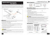
(Optional) Installing network port lightning
protectors
IMPORTANT:
• Before installing a network port lightning protector, read the instructions in the document that
comes with the protector.
• Network port lightning protectors are available only for 10M/100M/1000M RJ-45 Ethernet coppe
r
ports.
• If multiple network ports have network cables routed outdoors, install a network port lightning
protector for each network port.
If part of the network cable for a network port is routed outdoors, install a network port lightning
protector for the port to protect against damages caused by lightning strikes.
No network port lightning protectors are provided with the device. Purchase them yourself as
required.
To install a network port lightning protector for a network port:
1. Use a double-faced adhesive tape to stick the network port lightning protector onto the device
chassis, and make sure it is as close to the grounding screw of the device as possible.
2. Cut the ground wire of the protector to a length (as short as possible) as required by the
distance between the protector and the grounding screw of the device. Attach the ground wire
securely to the grounding screw of the device.
Make sure the grounding screw of the device is reliably grounded.
3. Use a multimeter to verify that the ground wire of the protector makes good contact with the
grounding screw of the chassis.
4. Insert the outdoor network cable into the protector's Surge end, and insert the cable from the
network port into the Protect end.
5. Examine the port LED to verify that the port is operating correctly.

12
Figure 13 Installing a lightning protector for a network port
(Optional) Installing a surge protected power strip
IMPORTANT:
Before installing a surge protected power strip, read the instructions in the document that comes
with the strip.
If you use an AC power line routed from outdoors for the device, use a surge protected power strip
for the device to protect against damages caused by lightning strikes. No surge protected power strip
is provided with the device. Purchase one yourself if required.
To use a surge protected power strip, first connect the AC power line routed from outdoors to the strip
and then connect the power cord from the device to the strip.
You can attach the surge protected power strip to the rack, workbench, or wall of the equipment
room.
Connecting the device to the network
1. Connect a WAN port on the device to the uplink network.
2. Connect the LAN ports to APs directly or through a switch. In Figure 14, the LA
N ports are
connected to APs directly.

13
Figure 14 Connecting the device to the network
Connecting the power cord
CAUTION:
Before connecting the power cord, make sure the local AC power source is reliably grounded.
Connecting the power adapter for the
WX1804H-PWR/WX1820H access controller
If you use the local power source for the WX1804H-PWR/WX1820H access controller, use a power
adapter to connect the device to the power source.
To connect the power adapter for the WX1804H-PWR/WX1820H access controller:
1. Make sure the device is reliably grounded.
2. Connect the power adapter to the DC power receptacle on the front panel of the device.
3. Connect the power adapter to the power source.
4. Observe the LEDs on the device to verify that the power adapter is connected correctly. For
information about LEDs, see "Appendix A Chassis views and technical specifications."
Figure 15 Connecting the power adapter for the WX1804H-PWR/WX1820H access controller
/