Page is loading ...

HC10
Hay Conditioner
Setup, Operation, and Parts Manual
215126 Revision A
Original Instruction
The Harvesting Specialists.

MacDon HC10 Hay Conditioner
1030791
Published October 2019.
© 2019 MacDon Industries, Ltd.
The information in this publication is based on the information available and in effect at the time of printing. MacDon
Industries, Ltd. makes no representation or warranty of any kind, whether expressed or implied, with respect to the
information in this publication. MacDon Industries, Ltd. reserves the right to make changes at any time without notice.

Introduction
This manual contains safety information, setup instructions, operating and maintenance procedures, and parts information
for the MacDon HC10 Hay Conditioner.
Conditioning or crimping cut hay allows moisture release for quicker drying and earlier processing. This hay conditioner,
when teamed with an M Series Self-Propelled Windrower and a timed double-knife drive D60, D65, or D1 Series Draper
Header, will condition crop cut by the header, which the windrower lays into uniform, fluffy windrows.
NOTE:
The HC10 is ONLY compatible with D60, D65, and D1 Series Headers that are 4.6–9.1 m (15–30 ft.) in length and equipped
with a timed double-knife. To avoid excessive vibration and poor performance, the HC10 Hay Conditioner should NOT be
attached to single-knife drive headers.
When setting up the machine or making adjustments, review and follow the recommended machine settings in all relevant
MacDon publications. Failure to do so may compromise machine function and machine life and may result in a hazardous
situation.
The HC10 Hay Conditioner is NOT intended for use with the M205 Self-Propelled Windrower. Refer to the following table
to determine if the HC10 Hay Conditioner is compatible with your windrower in your market:
Windrower (North America only)
MacDon M150, M155, M155E4, and M200 Self-Propelled Windrowers
Windrower (Export only)
MacDon M100, M105, M150, M155, and M200 Self-Propelled Windrowers
CAREFULLY READ ALL THE MATERIAL PROVIDED BEFORE ATTEMPTING TO UNLOAD, ASSEMBLE, OR USE THE MACHINE.
Use this manual as your first source of information about the machine. If you follow the instructions given in this manual,
your hay conditioner will work well for many years. Use this manual in conjunction with your windrower and draper header
manuals.
Use the Table of Contents and Index to guide you to specific topics. Review the Table of Contents to familiarize yourself
with how the material is organized.
Keep this manual handy for frequent reference and to pass on to new Operators or Owners. Call your Dealer if you need
assistance, information, or additional copies of this manual.
Warranty information
MacDon provides warranty for Customers who operate and maintain their equipment as described in this manual. A copy
of the MacDon Industries Limited Warranty Policy, which explains this warranty, should have been provided to you by your
Dealer. Damage resulting from any of the following conditions will void the warranty:
• Accident
• Misuse
• Abuse
• Improper maintenance or neglect
• Abnormal or extraordinary use of the machine
• Failure to use the machine, equipment, component, or part in accordance with the manufacturer’s instructions
Conventions
Right and left are determined from the operator’s position. The front of the header and of the hay conditioner is the side
that faces the crop; the back is the side that connects to the windrower.
NOTE:
Keep your MacDon publications up-to-date. The most current version can be downloaded from our website (www.macdon.
com) or from our Dealer-only site (https://portal.macdon.com) (login required).
215126 i Revision A


Summary of Changes
The following list provides an account of major changes from the previous version of this document.
Section
Summary of Change
Internal Use
Only
Front cover
Removed “D Series” from the cover because the HC10 is
compatible with specific lengths of D Series and D1 Series
headers.
Tech Pubs
Inside front cover
Added copyright and disclaimer. Tech Pubs
Introduction, page i
Specified which lengths of D Series and D1 Series headers
are compatible with the HC10. Added NOTE:
• The HC10 is only compatible with D60, D65, and D1
Series Headers that are 4.6–9.1 m (15–30 ft.) in length
and equipped with a timed double-knife. To avoid
excessive vibration and poor performance, the HC10
Hay Conditioner should NOT be attached to single-
knife drive headers.
Tech Pubs
Introduction, page i
Changed the term from “Carrier” to “Windrower” in
the table.
Tech Pubs
1 Safety, page 1 Added definition of IMPORTANT and NOTE.
Tech Pubs
2.1 Definitions, page 9 Added definition of D1 SP Series Header.
Engineering
2.2 Specifications, page 11 Revised the following specifications:
• Frame and Structure – Header: Now specifies a
“timed only ” double-knife drive. Added “D1 Series”
headers.
• Drives – Main Conditioner: Now
“80 cc (4.9 cu in.)” (no flow divider), was
51.83 cc (3.16 cu in.) hydraulic motor with
21.14 cc (1.29 cu in.) flow divider.
• Conditioner – Header Size: Added metric units.
• Conditioner – Header Size: Removed “35 ft.” header
from table and associated footnote.
• Conditioner – Roll Speed: Removed “695–868 rpm.”
• Conditioner
– Feed Draper Speed: Removed “393–
491 fpm.”
• Replaced the term “Export” with “outside of North
America” in the NOTE at the end of the topic.
Engineering
ECN 57949
3.1 Unloading the Hay Conditioner, page
15
• Step 3, page 16
Replaced “unit” with “forks and pallet” for clarity.
Tech Pubs
3.3 Installing the Rock Grate, page 18
• Step 2, page 18
• Step 6, page 18
Added or revised steps to include more detailed part
descriptions and/or instructions for retrieving parts.
Tech Pubs
215126 iii Revision A

Section
Summary of Change
Internal Use
Only
• Step 7, page 18
3.3 Installing the Rock Grate, page 18
• Step 8, page 18
Revised step to say “tighten nuts” instead of “tighten
bolts.”
Tech Pubs
3.4 Installing Deck Brackets, page 19
Created introductory topic because of the introduction of
adapter plate MD #159734.
ECN 58813
3.4.1 Installing Deck Brackets – D115,
D120, and D125, page 19
Created a new topic for D115, D120, and D125 headers to
include the introduction of adapter plate MD #159734.
Added part numbers and detailed descriptions of parts to
all steps where shown.
ECN 58813
3.4.2 Installing Deck Brackets – D60, D65,
and D130, page 22
Created topic for D60, D65, and D130 headers to exclude
the introduction of adapter plate MD #159734.
Added part numbers and detailed descriptions of parts to
all steps where shown.
ECN 58813
3.4.2 Installing Deck Brackets – D60, D65,
and D130, page 22
• Step 9, page 23
Revised step to say “tighten nuts” instead of “tighten
bolts.”
Tech Pubs
3.5 Installing the Feed Deck, page 24
• Step 1, page 24
Revised step to include instructions for retrieving parts. Tech Pubs
3.5 Installing the Feed Deck, page 24
• Step 4, page 24
• Step 5, page 25
• Revised steps and associated illustrations to correct
the installation location of the bolt and nut.
• Revised step to include more detailed part
descriptions and/or instructions for retrieving parts.
Tech Pubs
3.5 Installing the Feed Deck, page 24
• Step 6, page 25
Revised step to include more detailed part descriptions
and/or instructions for retrieving parts.
Tech Pubs
3.6.1 Installing Conditioner – Lifting
Method, page 26
Removed the following DANGER ONLY because the
machine is considered to be off at this time.
• To avoid bodily injury or death from unexpected start-
up or fall of a raised machine, always stop engine and
remove key before leaving the operator’s seat, and
always engage safety props before going under the
machine for any reason.
Tech Pubs
3.6.1 Installing Conditioner
– Lifting
Method, page 26
• Step 7, page 27
Revised step as follows:
• Now includes the nut.
• Added detailed part descriptions and/or instructions
for retrieving parts.
Tech Pubs
3.6.1 Installing Conditioner – Lifting
Method, page 26
• Step 8, page 27
Revised step as follows:
• Revised the illustration to correct the installation
location of the bolt and nut.
• Added detailed part descriptions and/or instructions
for retrieving parts.
Tech Pubs
215126 iv Revision A

Section
Summary of Change
Internal Use
Only
3.6.1 Installing Conditioner – Lifting
Method, page 26
• Step 9, page 28
Revised the illustration to include the new conditioner
drive motor and hose assembly adapter plate.
ECN 57949
ECN 58813
3.6.2 Installing Conditioner – Windrower
Method, page 28
• Step 4, page 29
Revised step to include more detailed part descriptions
and/or instructions for retrieving parts.
Tech Pubs
3.6.2 Installing Conditioner – Windrower
Method, page 28
• Step 6, page 29 to Step 13, page 30
Revised or added steps and illustrations for positioning
the lifting arms. The left lifting arm must now be removed
and reinstalled due to changes in design associated with
the new conditioner drive motor MD #159661.
ECN 57949
3.6.2 Installing Conditioner – Windrower
Method, page 28
• Step 14, page 30
• Step 15, page 30
• Step 16, page 30
• Step 17, page 30
• Step 22, page 31
• Step 23, page 31
Revised or added steps for safety and clarity.
Tech Pubs
3.6.2 Installing Conditioner – Windrower
Method, page 28
• Step 24, page 31 to Step 31, page 31
Revised or added steps and illustrations for positioning
the lifting arms. The left lifting arm must now be removed
and reinstalled due to changes in design associated with
the new conditioner drive motor MD #159661.
ECN 57949
3.6.2 Installing Conditioner – Windrower
Method, page 28
• Step 32, page 32
• Revised step to include more detailed part
descriptions and/or instructions for retrieving parts.
• Revised step to include the nut.
Tech Pubs
3.6.2 Installing Conditioner – Windrower
Method, page 28
• Step 33, page 32
• Revised step and associated illustration to correct the
installation location of the bolt and nut.
• Revised step to include more detailed part
descriptions and/or instructions for retrieving parts.
Tech Pubs
3.6.2 Installing Conditioner
– Windrower
Method, page 28
• Step 34, page 32
Revised the illustration to include the new conditioner
drive motor and hose assembly adapter plate.
ECN 57949
ECN 58813
3.7 Attaching Hydraulics, page 33 Added metric units to header size. Tech Pubs
3.7.1 Attaching Hydraulics – 4.6 m (15 ft.)
Headers, page 33
• Added “D Series Shown, D1 Series Similar” to all
captions.
• Added metric units to header size.
Tech Pubs
3.7.1 Attaching Hydraulics – 4.6 m (15 ft.)
Headers, page 33
• Step 5, page 34
• Rotated picture for clarity.
• Revised step to include more detailed part
descriptions and/or instructions for retrieving parts.
Tech Pubs
215126 v Revision A

Section
Summary of Change
Internal Use
Only
• Step 7, page 35
3.7.2 Attaching Hydraulics – All Headers
Except 4.6 m (15 ft.), page 36
• Added “D Series Shown, D1 Series Similar” to all
captions.
• Added metric units to header size.
• Remove step: “Identify the hydraulic coupler
components shown in the figure at right.”
Tech Pubs
3.8 Assembling the Forming Shield, page
38
• Step 1, page 38
• Step 3, page 38
Revised steps to include more detailed part descriptions
and/or instructions for retrieving parts.
Tech Pubs
3.9 Installing the Forming Shield, page 41
• Step 7, page 42
Revised step to include more detailed part descriptions
and/or instructions for retrieving parts.
Tech Pubs
3.10 Attaching to a Windrower, page 43
• Step 2, page 43
• Step 3, page 43
• Revised step to include more detailed part
descriptions and/or instructions for retrieving parts.
• Revised illustration and associated steps to identify all
parts involved.
Tech Pubs
3.12 Performing Predelivery Checks, page
47
Removed the following DANGER ONLY because the
machine is considered to be off at this time.
• To avoid bodily injury or death from unexpected start-
up of the machine, always stop the engine and
remove the key from the ignition before leaving the
operator’s seat for any reason.
Tech Pubs
3.12.2 Checking Roll Gap, page 48 Formatted content into steps. Tech Pubs
3.12.3 Checking Roll Timing, page 48 Removed the following DANGER and safety step ONLY
because the machine is considered to be off, and the
header is considered fully lowered, at this time:
• To avoid bodily injury or death from unexpected start-
up of the machine, always stop the engine and
remove the key from the ignition before leaving the
operator’s seat for any reason.
Tech Pubs
3.12.4 Running up the Conditioner, page
49
Removed the following CAUTION ONLY because this topic
contains another similar CAUTION:
• Clear the area of other persons, pets etc. Keep
children away from machinery. Walk around the
machine to be sure no one is under, on, or close to it.
Replaced the following CAUTION with the following
WARNING statement:
• CAUTION: Before investigating an unusual sound or
attempting to correct a problem, shut off engine,
engage parking brake, and remove key.
Tech Pubs
215126 vi Revision A

Section
Summary of Change
Internal Use
Only
• WARNING: To avoid injury or death from unexpected
start-up of machine, always stop the engine and
remove the key from the ignition before leaving the
operator’s seat for any reason.
3.12.4 Running up the Conditioner, page
49
• Step 1, page 49
Added safety steps:
• Clear all bystanders from the area.
Tech Pubs
3.12.4 Running up the Conditioner, page
49
• Step 3, page 49
• Step 4, page 49
Changed the term “machine” to “header” in these steps
for clarity.
Tech Pubs
3.12.4 Running up the Conditioner, page
49
• Step 6, page 49
Added safety step:
• Shut down the engine, and remove the key from
the ignition.
Tech Pubs
4.2 Operational Safety, page 52 Added “header” to the following CAUTION:
• Follow all safety and operational instructions given in
your windrower and header operator's manuals. If you
do not have a windrower and/or header manual, get
one from your Dealer and read it thoroughly.
Tech Pubs
4.4.1 Detaching Hay Conditioner –
Windrower Method, page 54
Replaced the following CAUTION with the following
WARNING statement:
• CAUTION: To prevent accidental movement of
windrower, return GSL to N-DETENT, center steering
wheel to lock, shut off engine, and remove key.
• WARNING: To avoid injury or death from unexpected
start-up of machine, always stop the engine and
remove the key from the ignition before leaving the
operator’s seat for any reason.
Tech Pubs
4.4.1 Detaching Hay Conditioner –
Windrower Method, page 54
• Step 1, page 54
Added safety step:
• Shut down the engine, and remove the key from
the ignition.
Tech Pubs
4.4.1 Detaching Hay Conditioner –
Windrower Method, page 54
• Step 6, page 55
Revised the illustration to include the new conditioner
drive motor and hose assembly adapter plate.
ECN 57949
ECN 58813
4.4.1 Detaching Hay Conditioner –
Windrower Method, page 54
• Step 7, page 55
Revised step to include the nut. Tech Pubs
4.4.1 Detaching Hay Conditioner –
Windrower Method, page 54
• Step 8, page 56
Revised step and associated illustration to correct the
installation location of the bolt and nut.
Tech Pubs
215126 vii Revision A

Section
Summary of Change
Internal Use
Only
4.4.1 Detaching Hay Conditioner –
Windrower Method, page 54
• Step 9, page 56 to Step 16, page 56
Revised or added steps and illustrations for positioning
the lifting arms. The left lifting arm must now be removed
and reinstalled due to changes in design associated with
the new conditioner drive motor MD #159661.
ECN 57949
4.4.2 Detaching Hay Conditioner – Lifting
Method, page 58
Replaced the following CAUTION with the following
WARNING statement:
• CAUTION: To prevent accidental movement of
windrower, return GSL to N-DETENT, center steering
wheel to lock, shut off engine, and remove key.
• WARNING: To avoid injury or death from unexpected
start-up of machine, always stop the engine and
remove the key from the ignition before leaving the
operator’s seat for any reason.
Tech Pubs
4.4.2 Detaching Hay Conditioner – Lifting
Method, page 58
• Step 1, page 58
Added safety step:
• Shut down the engine, and remove the key from
the ignition.
Tech Pubs
4.4.2 Detaching Hay Conditioner – Lifting
Method, page 58
• Step 6, page 59
Revised the illustration to include the new conditioner
drive motor and hose assembly adapter plate.
ECN 57949
ECN 58813
4.4.2 Detaching Hay Conditioner – Lifting
Method, page 58
• Step 7, page 60
Revised step to include the nut. Tech Pubs
4.4.2 Detaching Hay Conditioner – Lifting
Method, page 58
• Step 8, page 60
Revised step and associated illustration to correct the
installation location of the bolt and nut.
Tech Pubs
4.5 Detaching Feed Deck and Rock Grate,
page 62
• Step 2, page 62
• Step 3, page 62
Revised steps and associated illustrations to correct the
installation location of the bolt and nut.
Tech Pubs
4.6 Break-in Period, page 65
Replaced the following CAUTION with the following
WARNING statement:
• CAUTION: Before investigating an unusual sound or
attempting to correct a problem, shut off engine,
engage parking brake, and remove key.
• WARNING: To avoid injury or death from unexpected
start-up of machine, always stop the engine and
remove the key from the ignition before leaving the
operator’s seat for any reason.
Tech Pubs
4.9 Conditioner Operation, page 68
Revised the WARNING to specify a distance of
100 m (300 ft.):
• Keep hands and feet away from discharge opening.
Keep everyone at least 100 meters (330 ft.) away from
your operation. Never direct the discharge toward
Tech Pubs
215126 viii Revision A

Section
Summary of Change
Internal Use
Only
anyone. Stones or other foreign objects can be
ejected with force.
4.9.4 Adjusting Conditioner Roll Tension ,
page 70
• Step 2, page 70
Added safety step:
• Engage the header safety props.
Tech Pubs
Adjusting Forming Shield Height, page 71 Changed the following statement from a DANGER to a
WARNING for consistency:
• To avoid bodily injury or death from unexpected start-
up of the machine, always stop the engine and
remove the key from the ignition before leaving the
operator’s seat for any reason.
Tech Pubs
Adjusting Forming Shield Height, page 71
• Step 1, page 71
Added safety step:
• Shut down the engine, and remove the key from
the ignition.
Tech Pubs
Adjusting Side Deflectors, page 71 Changed the following statement from a DANGER to a
WARNING for consistency:
• To avoid bodily injury or death from unexpected start-
up of the machine, always stop the engine and
remove the key from the ignition before leaving the
operator’s seat for any reason.
Tech Pubs
Adjusting Side Deflectors, page 71
• Step 1, page 71
Added safety step:
• Shut down the engine, and remove the key from
the ignition.
Tech Pubs
Adjusting Rear Deflector (Fluffer Shield),
page 72
Changed the following statement from a DANGER to a
WARNING for consistency:
• To avoid bodily injury or death from unexpected start-
up of the machine, always stop the engine and
remove the key from the ignition before leaving the
operator’s seat for any reason.
Tech Pubs
Adjusting Rear Deflector (Fluffer Shield),
page 72
• Step 1, page 72
Added safety step:
• Shut down the engine, and remove the key from
the ignition.
Tech Pubs
Adjusting Deflector Fins, page 72 Changed the following statement from a DANGER to a
WARNING for consistency:
• To avoid bodily injury or death from unexpected start-
up of the machine, always stop the engine and
remove the key from the ignition before leaving the
operator’s seat for any reason.
Tech Pubs
Adjusting Deflector Fins, page 72
• Step 1, page 72
Added safety step:
• Shut down the engine, and remove the key from
the ignition.
Tech Pubs
215126 ix Revision A

Section
Summary of Change
Internal Use
Only
5.1 Preparation for Servicing, page 75 Replaced the following CAUTION with the following
DANGER:
• CAUTION: To avoid personal injury, before servicing
hay conditioner or opening header drive covers:
• DANGER: To avoid bodily injury or death from
unexpected start-up or fall of a raised machine, always
stop engine and remove key before leaving the
operator’s seat, and always engage safety props
before going under the machine for any reason.
Tech Pubs
5.7.1 Adjusting Drive Belt Tension, page 81
• Step 1, page 81
• Step 2, page 81
Added safety steps:
• Shut down the engine, and remove the key from
the ignition.
• Engage the header safety props.
Tech Pubs
5.7.1 Adjusting Drive Belt Tension, page 81
• Step 4, page 81 to Step 8, page 82
Revised steps and associated illustrations to include new
conditioner drive motor MD #159661.
ECN 57949
5.7.2 Adjusting Drive Belt Pulley Alignment,
page 82
• Step 1, page 82
• Step 2, page 82
Added introductory safety steps and the following
DANGER:
• To avoid bodily injury or death from unexpected start-
up or fall of a raised machine, always stop engine and
remove key before leaving the operator’s seat, and
always engage safety props before going under the
machine for any reason.
Tech Pubs
5.7.2 Adjusting Drive Belt Pulley Alignment,
page 82
• Refer to NOTE below Step 6, page 83
Revised NOTE and associated illustration to include new
conditioner drive motor MD #159661.
ECN 57949
5.7.3 Checking and Adjusting Drive Belt
Tracking, page 84
• Step 1, page 84
• Step 2, page 84.
Added safety steps:
• Shut down the engine, and remove the key from
the ignition.
• Engage the header safety props.
Tech Pubs
5.7.3 Checking and Adjusting Drive Belt
Tracking, page 84
• Step 4, page 84 to Step .
Revised steps and associated illustrations to include new
conditioner drive motor MD #159661.
ECN 57949
5.7.4 Removing Drive Belt, page 85
• Step 1, page 86
• Step 2, page 86
Added safety steps.
• Shut down the engine, and remove the key from
the ignition.
• Engage the header safety props.
Tech Pubs
5.7.4 Removing Drive Belt, page 85
• Refer to NOTE below Step 6, page 86
Revised NOTE and associated illustration to include new
conditioner drive motor MD #159661.
ECN 57949
5.7.5 Installing Drive Belt, page 86
• Step 1, page 86
Added introductory safety steps.
Tech Pubs
215126 x Revision A

Section
Summary of Change
Internal Use
Only
• Step 2, page 86
• Shut down the engine, and remove the key from
the ignition.
• Engage the header safety props.
5.7.5 Installing Drive Belt, page 86
• Step 3, page 87 to Step 7, page 87
Revised steps and associated illustrations to include new
conditioner drive motor MD #159661.
ECN 57949
6.1 Abbreviations, page 91 Added list abbreviations used by other parts catalogues
for consistency.
Tech Pubs
6.3 Lower Roll and Frame Assembly, page
94
Revised the parts list and illustration as follows:
• MD #18523 superseded all instances of MD #18524.
on this parts list.
ECN 57949
6.4 Upper Roll Assembly, page 96
Revised the parts list and illustration as follows due to
changes in design:
• MD #159707 supersedes MD #130644
• MD #159706 supersedes MD #130527
ECN 56836
6.5 Cover and Supports, page 98
Revised the parts list and illustration as follows due to
changes in design:
• Added MD #103562
• Bolt MD #103562 is now used instead of MD #18523
at some locations. Revised illustration to distinguish
between similar bolts MD #103562 and MD #18523.
ECN 57949
6.5 Cover and Supports, page 98
Added the following part previously missing from the
parts list and illustration:
• MD #14338
Tech Pubs
6.6 Hydraulic Motor, Mounts, and
Tensioner – Motor MD #159661, page 102
Added new topic, parts list and illustration to include the
introduction of conditioner drive motor MD# 159661.
ECN 57949
6.7 Hydraulic Motor, Mounts, and
Tensioner – Motor MD #159648, page 106
Revised topic title. Parts list and illustration only applies
to HC10 equipped with old conditioner drive motor
MD# 159648.
Added footnote:
• If replacing the motor, upgrade the motor and
associated components (sprocket, hydraulics) using kit
MD #159717.
ECN 57949
6.7 Hydraulic Motor, Mounts, and
Tensioner – Motor MD #159648, page 106
Added footnote to MD# 159648:
• Service motor shaft with item 27 (MD #159692).
Revised parts list and illustration to show all serviceable
parts included with motor shaft kit (MD #159692).
Specified that motor shaft kit (MD #159692) applies to
motor (MD #159648).
Product
Support
6.7 Hydraulic Motor, Mounts, and
Tensioner – Motor MD #159648, page 106
Revised the description of the surface protection of the
following parts:
ECN 57123
215126 xi Revision A

Section
Summary of Change
Internal Use
Only
• MD #50186: Now “NUT – FLG LK DT 1/2-13 UNC GR5
AA1J” was “ NUT – FLANGE LOCK SM FACE DT 0.500-
13UNC GR5”
• MD #30228: Now “NUT-FLG DT SM FACE 3/8-16UNC-
GR5-AA1J” was “ NUT – FLANGE DT SMOOTH FACE
0.375-16UNC”
6.8 Belt Drive and Shield – Motor
MD #159661, page 110
Added new topic, parts list and illustration to include the
introduction of conditioner drive motor MD# 159661.
ECN 57949
6.9 Belt Drive and Shield – Motor MD
#159648, page 112
Revised topic title. Parts list and illustration only applies
to HC10 equipped with old conditioner drive motor
MD# 159648.
ECN 57949
6.9 Belt Drive and Shield – Motor MD
#159648, page 112
Corrected the position of bushing MD# 130880 on the
illustration.
Added the following parts previously missing from the
parts list and illustration:
• MD #18638
• MD #21880
Tech Pubs
6.10 Hydraulic Completion Package –
Motor MD #159661, page 114
Added new topic, parts list and illustration to include
hydraulic parts required for the new conditioner drive
motor MD# 159661
ECN 58813
6.11 Hydraulic Completion Package –
Motor MD #159648, page 118
Removed the following discontinued seal kits from the
parts list:
• MD #135481
• MD #111977
ECN 47629
6.11 Hydraulic Completion Package –
Motor MD #159648, page 118
Corrected the parts list and illustration as follows:
• Corrected the quantity of cable tie MD #40704 to
three.
• Moved cable ties MD #40704 and MD #40703 on the
parts illustration.
• Corrected the quantity of cap MD #30999 to three.
Tech Pubs
6.12 Gears and Roll Coupling Assembly –
New (With Washer MD #30441), page 122
Created a new topic due to changes in design:
• MD #30441 (quantity of four) supersedes
MD #130688 (quantity of eight).
ECN 57069
6.13 Gears and Roll Coupling Assembly –
Old (With Washer MD #130688), page 124
Added footnote to washer MD #130688:
• Replace each pair of washers with
one new washer
(MD #30441). You do NOT have to replace all four
pairs of washers (MD #130688) with new washers
(MD #30441) at the same time. For the installation
location of new washer (MD #30441), refer to 6.12
Gears and Roll Coupling Assembly – New (With
Washer MD #30441), page 122
ECN 57069
6.15 Feed Deck and Pan, page 128 Revised the parts list as follows due to changes in design:
ECN 56836
215126 xii Revision A

Section
Summary of Change
Internal Use
Only
• MD #159704 supersedes MD #133838
6.15 Feed Deck and Pan, page 128
Revised the parts list as follows due to changes in design:
• Removed MD #135481. A seal kit is no longer offered
for MD #135213
ECN 47629
6.15 Feed Deck and Pan, page 128 Revised the parts list as follows:
• Added “(Faster)” to the description of MD #135386”.
Added a footnote regarding the Parker Hannifin
coupler.
• Added “(Faster)” to the description of MD #111978”.
Added a footnote to this part.
ECN 58441
6.15 Feed Deck and Pan, page 128
Corrected the parts list as follows:
• Changed MD #135630 toMD #49671.
• Changed MD #135626 toMD #30669.
Tech Pubs
6.16 Mounting Brackets, page 132 Revised the parts list and illustration as follows due to
changes in design for D115, D120, and D125 headers
equipped with a double-knife and single reel:
• Added MD #159734
• Added MD #113611
• Added additional MD #50225
ECN 58813
6.16 Mounting Brackets, page 132
Corrected the location of one nutMD #50225. and bolt
MD #18523. on the parts illustration.
Tech Pubs
7.1.8 Tapered Pipe Thread Fittings, page
145
• Step 4, page 145
Added “flats from finger tight (FFFT)” to step.
Tech Pubs
• 7.3.1 D1 Series Header – 4.6–9.1 m
(15–30 ft.), Timed Double Knife, Single
Reel, Hydraulic Deck Shift, HC10 (Motor
MD #159661), and Upper Cross Auger,
page 147
• 7.3.2 D1 Series Header – 4.6–9.1 m
(15–30 ft.), Timed Double Knife, Single
Reel, Hydraulic Deck Shift, and HC10
(Motor MD #159661), page 151
• 7.3.3 D1 Series Header – 9.1 m (30 ft.),
Timed Double Knife, Double Reel,
Hydraulic Deck Shift, HC10
(Motor MD #159661), and Upper Cross
Auger, page 155
• 7.3.4 D1 Series Header – 9.1 m (30 ft.),
Timed Double Knife, Double Reel,
Hydraulic Deck Shift, and HC10
(Motor MD #159661), page 159
Created new hydraulic schematics to replace all previous
schematics and to show more header configurations
compatible with the HC10 (motor MD #159661).
Tech Pubs
215126 xiii Revision A

Section
Summary of Change
Internal Use
Only
• 7.3.5 D60/D65 Header – 4.6–9.1 m
(15–30 ft.). Timed Double Knife, Single
Reel, Hydraulic Deck Shift, HC10
(Motor MD #159661), and Upper Cross
Auger, page 163
• 7.3.6 D60/D65 Header – 4.6–9.1 m
(15–30 ft.), Timed Double Knife, Single
Reel, Hydraulic Deck Shift, and HC10
(Motor MD #159661), page 167
• 7.3.7 D60/D65 Header – 9.1 m (30 ft.),
Timed Double Knife, Double Reel,
Hydraulic Deck Shift, HC10
(Motor MD #159661), and Upper Cross
Auger, page 171
• 7.3.8 D60/D65 Header – 9.1 m (30 ft.),
Timed Double Knife, Double Reel,
Hydraulic Deck Shift, and HC10
(Motor MD #159661), page 175
• 7.4.1 D1 Series Header – 4.6–9.1 m
(15–30 ft.), Timed Double Knife, Single
Reel, Hydraulic Deck Shift, HC10
(Motor MD #159648), and Upper Cross
Auger, page 179
• 7.4.2 D1 Series Header – 4.6–9.1 m
(15–30 ft.), Timed Double Knife, Single
Reel, Hydraulic Deck Shift, and HC10
(Motor MD #159648), page 183
• 7.4.3 D1 Series Header – 9.1 m (30 ft.),
Timed Double Knife, Double Reel,
Hydraulic Deck Shift, HC10
(Motor MD #159648), and Upper Cross
Auger, page 187
• 7.4.4 D1 Series Header – 9.1 m (30 ft.),
Timed Double Knife, Double Reel,
Hydraulic Deck Shift, and HC10
(Motor MD #159648), page 191
• 7.4.5 D60/D65 Header – 4.6–9.1 m
(15–30 ft.), Timed Double Knife, Single
Reel, Hydraulic Deck Shift, HC10
(Motor MD #159648), and Upper Cross
Auger, page 195
• 7.4.6 D60/D65 Header – 4.6–9.1 m
(15–30 ft.), Timed Double Knife, Single
Reel, Hydraulic Deck Shift, and HC10
(Motor MD #159648), page 199
• 7.4.7 D60/D65 Header – 9.1 m (30 ft.),
Timed Double Knife, Double Reel,
Created new hydraulic schematics to replace all previous
schematics and to show more header configurations
compatible with the HC10 (motor MD #159648).
Tech Pubs
215126 xiv Revision A

Section
Summary of Change
Internal Use
Only
Hydraulic Deck Shift, HC10
(Motor MD #159648), and Upper Cross
Auger, page 203
• 7.4.8 D60/D65 Header – 9.1 m (30 ft.),
Timed Double Knife, Double Reel,
Hydraulic Deck Shift, and HC10
(Motor MD #159648), page 207
Index Added all serviceable part numbers to the index. Tech Pubs
215126 xv Revision A

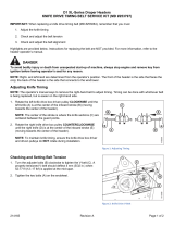
Serial Numbers
Record the serial number of the hay conditioner in the space below.
Hay Conditioner Serial Number: ____________
Serial number plate (A) is located on the rear cover of the conditioner frame as shown below.
1005038
A
Figure 1: Serial Number Plate
215126 xvi Revision A

215126 xvii Revision A
Introduction ................................................................................................................................................i
Summary of Changes................................................................................................................................... iii
Serial Numbers ..........................................................................................................................................xvi
Chapter 1: Safety .................................................................... .................................................................... 1
1.1 Safety Alert Symbols ...............................................................................................................................1
1.2 Signal Words ......................................................................................................................................... 2
1.3 General Safety .......................................................................................................................................3
1.4 Maintenance Safety ................................................................................................................................ 5
1.5 Hydraulic Safety ..................................................................................................................................... 6
1.6 Safety Signs ........................................................................................................................................... 7
1.6.1 Installing Safety Decals.................................................................................................................... 7
Chapter 2: Product Overview............................................. ........................................................................ 9
2.1 Definitions ............................................................................................................................................ 9
2.2 Specifications....................................................................................................................................... 11
2.3 Component Identification ...................................................................................................................... 12
Chapter 3: Unloading and Assembly.................................................................. ...................................... 15
3.1 Unloading the Hay Conditioner ............................................................................................................... 15
3.2 Preparing the Header ............................................................................................................................ 17
3.3 Installing the Rock Grate........................................................................................................................ 18
3.4 Installing Deck Brackets ......................................................................................................................... 19
3.4.1 Installing Deck Brackets – D115, D120, and D125............................................................................... 19
3.4.2 Installing Deck Brackets – D60, D65, and D130 .................................................................................. 22
3.5 Installing the Feed Deck......................................................................................................................... 24
3.6 Installing the Conditioner....................................................................................................................... 26
3.6.1 Installing Conditioner – Lifting Method ............................................................................................ 26
3.6.2 Installing Conditioner – Windrower Method ..................................................................................... 28
3.7 Attaching Hydraulics ............................................................................................................................. 33
3.7.1 Attaching Hydraulics – 4.6 m (15 ft.) Headers.................................................................................... 33
3.7.2 Attaching Hydraulics – All Headers Except 4.6 m (15 ft.)...................................................................... 36
3.8 Assembling the Forming Shield ............................................................................................................... 38
3.9 Installing the Forming Shield................................................................................................................... 41
3.10 Attaching to a Windrower .................................................................................................................... 43
3.11 Lubricating the Conditioner .................................................................................................................. 44
3.11.1 Greasing Procedure .................................................................................................................... 44
3.11.2 Lubrication Points ......................................................................................................................45
3.12 Performing Predelivery Checks .............................................................................................................. 47
3.12.1 Checking Roll Drive Belt Tension ................................................................................................... 47
3.12.2 Checking Roll Gap....................................................................................................................... 48
3.12.3 Checking Roll Timing ................................................................................................................... 48
TABLE OF CONTENTS

215126 xviii Revision A
3.12.4 Running up the Conditioner ......................................................................................................... 49
3.12.5 Storing Manuals......................................................................................................................... 50
Chapter 4: Operation................................................................................................................................ 51
4.1 Owner/Operator Responsibilities ............................................................................................................ 51
4.2 Operational Safety................................................................................................................................ 52
4.2.1 Shutting down the Machine ........................................................................................................... 52
4.3 Attaching Hay Conditioner to Header ....................................................................................................... 53
4.4 Detaching Hay Conditioner from Header .................................................................................................. 54
4.4.1 Detaching Hay Conditioner – Windrower Method.............................................................................. 54
4.4.2 Detaching Hay Conditioner – Lifting Method..................................................................................... 58
4.5 Detaching Feed Deck and Rock Grate ....................................................................................................... 62
4.6 Break-in Period .................................................................................................................................... 65
4.7 Preseason Check .................................................................................................................................. 66
4.8 Daily Startup Check............................................................................................................................... 67
4.9 Conditioner Operation........................................................................................................................... 68
4.9.1 Roll and Feed Draper Speed........................................................................................................... 68
4.9.2 Adjusting Roll Gap........................................................................................................................ 68
4.9.3 Checking and Adjusting Roll Timing ................................................................................................. 69
4.9.4 Adjusting Conditioner Roll Tension ................................................................................................. 70
4.9.5 Forming Shields ........................................................................................................................... 70
Adjusting Forming Shield Height.................................................................................................... 71
Adjusting Side Deflectors ............................................................................................................. 71
Adjusting Rear Deflector (Fluffer Shield) ......................................................................................... 72
Adjusting Deflector Fins ............................................................................................................... 72
4.9.6 Unplugging the Conditioner ........................................................................................................... 73
4.10 Storing the Hay Conditioner.................................................................................................................. 74
Chapter 5: Maintenance........................................................................................................................... 75
5.1 Preparation for Servicing ....................................................................................................................... 75
5.2 Recommended Safety Procedures ........................................................................................................... 76
5.3 Removing and Installing Driveshields ....................................................................................................... 77
5.4 Lubrication .......................................................................................................................................... 78
5.4.1 Lubricants................................................................................................................................... 78
5.4.2 Greasing Procedure ...................................................................................................................... 78
5.4.3 Greasing Points ........................................................................................................................... 78
5.5 Hydraulics ........................................................................................................................................... 79
5.5.1 Hydraulic Hoses and Lines ............................................................................................................. 79
5.5.2 Hydraulic Schematics .................................................................................................................... 79
5.6 Feed Draper ........................................................................................................................................ 80
5.6.1 Adjusting Feed Draper Tension ....................................................................................................... 80
5.7 Drive Belt ............................................................................................................................................ 81
5.7.1 Adjusting Drive Belt Tension .......................................................................................................... 81
TABLE OF CONTENTS
/