Page is loading ...

D1 Series
Draper Header for M Series Windrowers
Unloading and Assembly Instructions (North America)
215419 Revision A
Original Instruction
The Harvesting Specialists.

D1 Series Draper Header for M Series Windrowers
1025150
Published: August 2020
© 2020 MacDon Industries, Ltd.
The information in this publication is based on the information available and in effect at the time of printing. MacDon
Industries, Ltd. makes no representation or warranty of any kind, whether expressed or implied, with respect to the
information in this publication. MacDon Industries, Ltd. reserves the right to make changes at any time without notice.

Introduction
This instruction manual describes the unloading, setup, and predelivery requirements for the MacDon D1 Series Draper
Header for M Series Self-Propelled Windrowers.
To ensure the best performance of this product and the safety of your customers, carefully follow the unload and assembly
procedure from the beginning through to completion.
Carefully read all the material provided before attempting to unload, assemble, or use the machine.
Retain this instruction for future reference.
Conventions
The following conventions are used in this document:
• Right and left are determined from the operator’s position. The front of the header faces the crop.
• Unless otherwise noted, use the standard torque values provided in this manual.
NOTE:
Keep your MacDon publications up-to-date. The latest version can be downloaded from our website (www.macdon.com)or
from our Dealer portal (https://portal.macdon.com) (login required).
This document is currently available in English only.
215419 i Revision A

Summary of Changes
At MacDon, we’re continuously making improvements: occasionally these improvements affect product documentation.
The following list provides an account of major changes from the previous version of this document.
Section
Summary of Change
Internal Use
Only
Throughout
Removed references to D145 headers.
Tech Pubs
Throughout
The following type of statement is consistently a
WARNING throughout the manual:
• Equipment used for loading and unloading must meet
or exceed the minimum specified requirements. Using
inadequate equipment may result in vehicle tipping,
machine damage, or chain breakage.
• Check that all bystanders have cleared the area.
• Never start or move the machine until you are sure all
bystanders have cleared the area.
• Clear the area of other persons, pets etc. Keep
children away from machinery. Walk around the
machine to be sure no one is under, on, or close to it.
Tech Pubs
Throughout The following statement is consistently DANGER
throughout the manual:
• To avoid injury to bystanders from being struck by
machinery, do not allow people to stand in unloading
area.
Tech Pubs
Throughout The following statement is consistently a WARNING
throughout the manual:
• Do NOT exceed maximum pressure specified on tire
sidewall.
Tech Pubs
Introduction, page i Added conventions.
Tech Pubs
2.1 Unloading Header from Trailer, page 7
• Step 3, page 8
Revised step and illustration to include forklift brackets.
ECN 59347
2.2.1 Lowering Single-Reel Header, page 9
• Step 7, page 11
Added illustration of anchor pin for clarity. Tech Pubs
2.2.2 Lowering Double-Reel Header, page
12
• Step 3, page 12
Added NOTE to step. Tech Pubs
2.2.2 Lowering Double-Reel Header, page
12
• Step 7, page 14
Added illustration of anchor pin for clarity.
Tech Pubs
2.3 Removing Shipping Supports, page 16
• Step 3, page 16
• Step 4, page 17
Revised illustration to include forklift brackets.
ECN 59347
215419 ii Revision A

Section
Summary of Change
Internal Use
Only
3.1 Attaching Reel Lift Cylinders, page 19
• Step NA, page 19
Revised illustrations in step to correctly show North
American single and double reel brackets.
Tech Pubs
3.1 Attaching Reel Lift Cylinders, page 19
• Step 4, page 20
• Step 17, page 24
Revised illustrations to show change in hardware for the
center reel shipping bracket.
ECN 58360
3.1 Attaching Reel Lift Cylinders, page 19
• Step 19, page 25
Changed the NOTE to an IMPORTANT. Tech Pubs
3.2 Positioning Transport Lights, page 27
• Step 1, page 27
• Step 2, page 27
Removed P-clip from illustration of transport light.
ECN 58380
3.2 Positioning Transport Lights, page 27
• Step 3, page 27
Corrected position of transport light in illustration.
Tech Pubs
3.3 Attaching Cam Arms, page 29
• Step 7, page 30
Added IMPORTANT. Product
Support
4 Attaching Header to Windrower, page
37
• Step 1, page 37
Added safety step:
• Shut down the engine, and remove the key from
the ignition.
Tech Pubs
4 Attaching Header to Windrower, page
37
• Step 8, page 39
Revised illustration to show support plate. Product
Support
5.1 Checking Tire Pressure – Transport
and Stabilizer Wheels, page 53
Updated tire pressure chart to identify tires by load
ranges and revised pressure specifications accordingly.
ECN 42810
ECN 43062
5.4.1 Checking and Tensioning Single and
Untimed Double-Knife Drive Belts, page
57
Replaced the WARNING with the following DANGER:
• To avoid bodily injury or death from unexpected
startup of machine, always stop the engine and
remove the key before making adjustments to the
machine.
Tech Pubs
5.4.1 Checking and Tensioning Single and
Untimed Double-Knife Drive Belts, page
57
• Step 1, page 57
Added safety step:
• Shut down the engine, and remove the key from the
ignition.
Tech Pubs
5.4.1 Checking and Tensioning Single and
Untimed Double-Knife Drive Belts, page
57
• Step 10, page 58
Clarifies that step only applies to double-knife headers.
Tech Pubs
215419 iii Revision A

Section
Summary of Change
Internal Use
Only
5.4.2 Checking and Tensioning Timed
Double-Knife Drive Belts, page 58
Replaced the WARNING with the following DANGER:
• DANGER: To avoid bodily injury or death from
unexpected startup of machine, always stop the
engine and remove the key before making
adjustments to the machine.
Tech Pubs
5.5.1 Centering Double Reel, page 61
Replaced the WARNING with the following DANGER:
• DANGER: To avoid bodily injury or death from
unexpected startup of machine, always stop the
engine and remove the key before making
adjustments to the machine.
Tech Pubs
5.5.1 Centering Double Reel, page 61
• Step 2, page 61
Revised step and illustration for clarity. Tech Pubs
5.5.2 Centering Single Reel, page 63
Replaced the WARNING with the following DANGER:
• DANGER: To avoid bodily injury or death from
unexpected startup of machine, always stop the
engine and remove the key before making
adjustments to the machine.
Tech Pubs
5.5.2 Centering Single Reel, page 63
• Step 2, page 63
Added step and illustration for clarity. Tech Pubs
5.7 Checking and Adjusting Draper Seal,
page 66
Revised whole procedure. Steps now correspond to the
technical manual.
Tech Pubs
5.8 Checking and Adjusting Skid Shoe
Settings, page 69
• Step 1, page 69 to Step 3, page 69
• Step 6, page 69 to Step 8, page 69
Added safety steps.
Tech Pubs
5.11.1 Measuring Reel Clearance, page 72
Replaced the following DANGER with the following
WARNING only because safety props are not used for this
procedure:
• DANGER: To avoid bodily injury or death from
unexpected start-up or fall of raised machine, always
stop engine, remove key, and engage safety props
before going under header for any reason.
• WARNING: To avoid injury or death from unexpected
start-up of machine, always stop the engine and
remove the key from the ignition before leaving the
operator’s seat for any reason.
Tech Pubs
5.11.1 Measuring Reel Clearance, page 72
Flipped the order of the introductory WARNINGS.
Tech Pubs
5.11.1 Measuring Reel Clearance, page 72
• Step 6, page 73
Revised illustration to identify reel fingers.
Tech Pubs
215419 iv Revision A

Section
Summary of Change
Internal Use
Only
5.11.1 Measuring Reel Clearance, page 72
Removed the step that showed four locations to measure
the reel clearance (previously intended for double reel),
because there are only two locations at which to measure
the reel clearance for single and double reels on rigid
headers.
Tech Pubs
5.11 Reel Clearance to Cutterbar, page 72
• Table 5.2, page 72
Added clearance specification for D115.
Tech Pubs
5.11.2 Adjusting Reel Clearance, page 74
• Step 3, page 74
Moved safety step to this location. Tech Pubs
5.11.2 Adjusting Reel Clearance, page 74
• Step 10, page 74
Added safety step:
• Shut down the engine, and remove the key from
the ignition.
Tech Pubs
5.13.1 Greasing Procedure, page 79
• Step 1, page 79
Added safety step:
• Shut down the engine, and remove the key from
the ignition.
Tech Pubs
5.14 Checking Manuals, page 81 Corrected the list of manuals. Replaced “technical manual
with “parts catalog.”
Tech Pubs
6 Running up the Header, page 83 Replaced the following CAUTION with the following
DANGER:
• CAUTION: Before investigating an unusual sound or
attempting to correct a problem, shut off the engine,
engage the parking brake, and remove the key.
• DANGER: To avoid bodily injury or death from
unexpected startup of machine, always stop the
engine and remove the key before making
adjustments to the machine.
Tech Pubs
215419 v Revision A


215419 vii Revision A
Introduction ................................................................................................................................................i
Summary of Changes....................................................................................................................................ii
Chapter 1: Safety ............................................................................................................... ......................... 1
1.1 Signal Words ......................................................................................................................................... 1
1.2 General Safety ....................................................................................................................................... 2
1.3 Welding Precaution ................................................................................................................................ 4
1.4 Safety Signs ........................................................................................................................................... 5
Chapter 2: Unloading the Header .......................................... .................................................................... 7
2.1 Unloading Header from Trailer..................................................................................................................7
2.2 Lowering Header .................................................................................................................................... 9
2.2.1 Lowering Single-Reel Header............................................................................................................ 9
2.2.2 Lowering Double-Reel Header ........................................................................................................ 12
2.3 Removing Shipping Supports .................................................................................................................. 16
Chapter 3: Assembling the Header .......................................................................................................... 19
3.1 Attaching Reel Lift Cylinders ................................................................................................................... 19
3.2 Positioning Transport Lights ................................................................................................................... 27
3.3 Attaching Cam Arms ............................................................................................................................. 29
3.4 Opening Endshields .............................................................................................................................. 31
3.5 Installing Crop Dividers .......................................................................................................................... 32
3.6 Closing Endshields ................................................................................................................................ 34
3.7 Installing Disc Segments of Outboard Reel Endshields ................................................................................. 35
3.8 Installing Options ................................................................................................................................. 36
Chapter 4: Attaching Header to Windrower ........................................................................................... 37
4.1 Connecting Center-Link.......................................................................................................................... 39
4.1.1 Mechanical Link........................................................................................................................... 39
4.1.2 Hydraulic Link without Optional Self-Alignment Kit ............................................................................ 41
4.1.3 Hydraulic Link with Optional Self-Alignment Kit ................................................................................. 44
4.2 Connecting Hydraulics ........................................................................................................................... 47
4.3 Adding Tire Ballast................................................................................................................................ 51
Chapter 5: Performing Predelivery Checks.............................................................................................. 53
5.1 Checking Tire Pressure – Transport and Stabilizer Wheels............................................................................53
5.2 Checking Wheel Bolt Torque – Transport and Stabilizer Wheels .................................................................... 54
5.3 Checking Knife Drive Box ....................................................................................................................... 55
5.4 Checking and Adjusting Knife Drive Belt Tension ........................................................................................ 57
5.4.1 Checking and Tensioning Single and Untimed Double-Knife Drive Belts.................................................. 57
5.4.2 Checking and Tensioning Timed Double-Knife Drive Belts.................................................................... 58
5.4.3 Tensioning Timed Knife Drive V-Belts............................................................................................... 60
TABLE OF CONTENTS

215419 viii Revision A
5.5 Centering the Reel ................................................................................................................................ 61
5.5.1 Centering Double Reel .................................................................................................................. 61
5.5.2 Centering Single Reel .................................................................................................................... 63
5.6 Checking and Adjusting Draper Tension.................................................................................................... 64
5.7 Checking and Adjusting Draper Seal ......................................................................................................... 66
5.8 Checking and Adjusting Skid Shoe Settings ................................................................................................ 69
5.9 Leveling the Header .............................................................................................................................. 70
5.10 Checking and Adjusting the Float........................................................................................................... 71
5.11 Reel Clearance to Cutterbar.................................................................................................................. 72
5.11.1 Measuring Reel Clearance............................................................................................................ 72
5.11.2 Adjusting Reel Clearance ............................................................................................................. 74
5.12 Checking and Adjusting Endshields......................................................................................................... 75
5.13 Lubricating Header.............................................................................................................................. 79
5.13.1 Greasing Procedure .................................................................................................................... 79
5.13.2 Lubrication Points ...................................................................................................................... 80
5.14 Checking Manuals ............................................................................................................................... 81
Chapter 6: Running up the Header .......................................................................................................... 83
6.1 Performing Post Run-Up Adjustments ...................................................................................................... 83
6.1.1 Adjusting Knife ............................................................................................................................ 83
Chapter 7: Reference ............................................................................................................ .................... 85
7.1 Torque Specifications ............................................................................................................................ 85
7.1.1 Metric Bolt Specifications .............................................................................................................. 85
7.1.2 Metric Bolt Specifications Bolting into Cast Aluminum ........................................................................ 87
7.1.3 O-Ring Boss Hydraulic Fittings – Adjustable ...................................................................................... 88
7.1.4 O-Ring Boss Hydraulic Fittings – Non-Adjustable................................................................................ 90
7.1.5 O-Ring Face Seal Hydraulic Fittings.................................................................................................. 91
7.1.6 Tapered Pipe Thread Fittings.......................................................................................................... 92
7.2 Lifting Equipment Requirements ............................................................................................................. 94
7.3 Conversion Chart.................................................................................................................................. 95
7.4 Definitions .......................................................................................................................................... 96
Predelivery Checklist ................................................................................................................................ 99
TABLE OF CONTENTS

215419 1 Revision A
Chapter 1: Safety
1.1 Signal Words
Three signal words, DANGER, WARNING, and CAUTION, are used to alert you to hazardous situations. Two signal words,
IMPORTANT and NOTE, identify non-safety related information.
Signal words are selected using the following guidelines:
DANGER
Indicates an imminently hazardous situation that, if not avoided, will result in death or serious injury.
WARNING
Indicates a potentially hazardous situation that, if not avoided, could result in death or serious injury. It may also be
used to alert against unsafe practices.
CAUTION
Indicates a potentially hazardous situation that, if not avoided, may result in minor or moderate injury. It may be used
to alert against unsafe practices.
IMPORTANT:
Indicates a situation that, if not avoided, could result in a malfunction or damage to the machine.
NOTE:
Provides additional information or advice.

215419 2 Revision A
1.2 General Safety
Protect yourself when assembling, operating, and servicing machinery.
1000004
Figure 1.1: Safety Equipment
CAUTION
The following general farm safety precautions should be part of
your operating procedure for all types of machinery.
Wear all protective clothing and personal safety devices that
could be necessary for the job at hand. Do NOT take chances.
You may need the following:
• Hard hat
• Protective footwear with slip-resistant soles
• Protective glasses or goggles
• Heavy gloves
• Wet weather gear
• Respirator or filter mask
1000005
Figure 1.2: Safety Equipment
In addition, take the following precautions:
• Be aware that exposure to loud noises can cause hearing
impairment or loss. Wear suitable hearing protection devices
such as earmuffs or earplugs to help protect against loud
noises.
1010391
Figure 1.3: Safety Equipment
• Provide a first aid kit in case of emergencies.
• Keep a properly maintained fire extinguisher on the machine.
Be familiar with its proper use.
• Keep young children away from machinery at all times.
• Be aware that accidents often happen when the Operator is
tired or in a hurry. Take time to consider the safest way.
NEVER ignore warning signs of fatigue.
SAFETY

215419 3 Revision A
1000007
Figure 1.4: Safety around Equipment
• Wear close-fitting clothing and cover long hair. NEVER wear
dangling items such as scarves or bracelets.
• Keep all shields in place. NEVER alter or remove safety
equipment. Make sure driveline guards can rotate
independently of shaft and can telescope freely.
• Use only service and repair parts made or approved by
equipment manufacturer. Substituted parts may not meet
strength, design, or safety requirements.
1000008
Figure 1.5: Safety around Equipment
• Keep hands, feet, clothing, and hair away from moving parts.
NEVER attempt to clear obstructions or objects from a
machine while the engine is running.
• Do NOT modify the machine. Unauthorized modifications
may impair machine function and/or safety. It may also
shorten the machine’s life.
• To avoid injury or death from unexpected startup of the
machine, ALWAYS stop the engine and remove the key from
the ignition before leaving the operator’s seat for any reason.
1000009
Figure 1.6: Safety around Equipment
• Keep service area clean and dry. Wet and/or oily floors are
slippery. Wet spots can be dangerous when working with
electrical equipment. Be sure all electrical outlets and tools
are properly grounded.
• Keep work area well lit.
• Keep machinery clean. Straw and chaff on a hot engine are
fire hazards. Do NOT allow oil or grease to accumulate on
service platforms, ladders, or controls. Clean machines before
storage.
• NEVER use gasoline, naphtha, or any volatile material for
cleaning purposes. These materials may be toxic and/or
flammable.
• When storing machinery, cover sharp or extending
components to prevent injury from accidental contact.
SAFETY

215419 4 Revision A
1.3 Welding Precaution
To prevent damage to sensitive electronics, welding should never be attempted on the header while it is connected to a
windrower.
WARNING
Severe damage to sensitive, expensive electronics can result from welding on the header while it is connected to the
windrower. It can be impossible to know what effect high current could have with regard to future malfunctions or
shorter lifespan. It is very important that welding on the header is not attempted while the header is connected to the
windrower.
If it is unfeasible to disconnect the header from the windrower before welding, refer to the windrower’s technical manual
for welding precautions detailing all electrical components that must be disconnected first for safe welding.
SAFETY

215419 5 Revision A
1.4 Safety Signs
Safety signs (decals) are usually yellow, and are placed on the machine where there is a risk of personal injury, or where the
operator has to take extra precaution before operating controls. Operator manuals and technical manuals identify the
location and meaning of all safety signs placed on the machine.
1000694
Figure 1.7: Operator’s Manual Decal
• Keep safety signs clean and legible at all times.
• Replace safety signs that are missing or illegible.
• If the original part on which a safety sign was installed is
replaced, be sure the repair part displays the current
safety sign.
SAFETY


215419 7 Revision A
Chapter 2: Unloading the Header
Perform all procedures in this chapter in the order they are listed.
2.1 Unloading Header from Trailer
The following procedure assumes that two headers were shipped on the trailer.
DANGER
To avoid injury to bystanders from being struck by machinery, do NOT allow people to stand in unloading area.
WARNING
Equipment used for loading and unloading must meet or exceed the minimum specified requirements. Using
inadequate equipment may result in vehicle tipping, machine damage, or chain breakage.
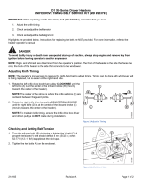
IMPORTANT:
Forklifts are normally rated with the load centered 610 mm (24 in.) from the back end of forks. To obtain forklift capacity
for a load centered at 1220 mm (48 in.), check with your forklift distributor.
1013855
A
B
C
Figure 2.1: Minimum Lifting Capacity
A - Load Center of Gravity
B - Load Center 1220 mm (48 in.) from Back of Forks
C - Minimum Fork Length 1981 mm (78 in.)
Table 2.1 Lifting Vehicle
Minimum Lifting Capacity
3178 kg (7000 lb.)
load center (A) at 1220 mm
(48 in.) (B) from the back of
the forks
Minimum Fork Length (C) 1981 mm (78 in.)
To unload the headers from a trailer, follow these steps:
1. Move the trailer into position and block the trailer wheels.
2. Lower the trailer storage stands.

215419 8 Revision A
AB
C
B
1033575
A
A
B
Figure 2.2: Header Shipping Supports
3. Approach one of the headers and slide forks (A) through
four forklift brackets (B) underneath the shipping support,
as far as possible without contacting the shipping support
of second header (C).
IMPORTANT:
Avoid lifting the second header and ensure the forks do not
interfere with the shipping frame. If the forks contact the
second header, the header could be damaged.
4. Remove the hauler’s tie-down straps, chains, and wooden
blocks.
5. Slowly raise the header off the trailer deck.
WARNING
Be sure forks are secure before moving away from load. Stand
clear when lifting.
6. Back up until the header clears the trailer and slowly lower
it to 150 mm (6 in.) from the ground.
7. Take the header to the storage or setup area. Ensure the
ground is flat and free of rocks or debris that could damage
the header.
8. Repeat the previous steps for unloading the second header.
9. Check for shipping damage and missing parts.
UNLOADING THE HEADER

215419 9 Revision A
2.2 Lowering Header
The procedure for lowering the header varies depending on whether the header has a single or double reel.
To lower the header, refer to the procedure according to the type of header:
• Single-reel headers: refer to 2.2.1 Lowering Single-Reel Header, page 9.
• Double-reel headers: refer to2.2.2 Lowering Double-Reel Header, page 12
2.2.1 Lowering Single-Reel Header
Lower the header to prepare it for assembly and setup.
To lower the header, follow these steps:
1008905
A
B
Figure 2.3: Shipping Frame
1. Choose an area with level ground.
2. Approach header from its underside and place forks under
top of shipping frame (A).
3. Attach a chain (B) at each end of the shipping frame and
secure other end to lifting vehicle.
UNLOADING THE HEADER

/