
Crestron IPAC-GL1
Integrated Professional Automation Computer
Setup Guide (Default Program v1.2.1)

This document was prepared and written by the Technical Documentation department at:
Crestron Electronics, Inc.
15 Volvo Drive
Rockleigh, NJ 07647
1-888-CRESTRON
Industry Compliance
This product is Listed to applicable UL Standards and requirements by Underwriters Laboratories Inc.
Federal Communications Commission (FCC) Compliance Statement
This device complies with part 15 of the FCC rules. Operation is subject to the following conditions:
(1) this device may not cause harmful interference and (2) this device must accept any interference received,
including interference that may cause undesired operation.
CAUTION: Changes or modifications not expressly approved by the manufacturer responsible for compliance
could void the user’s authority to operate the equipment.
NOTE: This equipment has been tested and found to comply with the limits for a Class B digital device,
pursuant to part 15 of the FCC rules. These limits are designed to provide reasonable protection against harmful
interference in a residential installation. This equipment generates, uses and can radiate radio frequency energy
and if not installed and used in accordance with the instructions, may cause harmful interference to radio
communications. However, there is no guarantee that interference will not occur in a particular installation. If
this equipment does cause harmful interference to radio or television reception, which can be determined by
turning the equipment off and on, the user is encouraged to try to correct the interference by one or more of the
following measures:
Reorient or relocate the receiving antenna
Increase separation between the equipment and the receiver
Connect the equipment into an outlet on a circuit different from that to which the receiver is connected
Consult the dealer or an experienced radio/TV technician for help
As of the date of manufacture, the IPAC-GL1 has been tested and found to comply with specifications for CE
marking and standards per EMC and Radiocommunications Compliance Labelling.
(E174344)
All brand names, product names and trademarks are the property of their respective owners.
©2009 Crestron Electronics, Inc.

Crestron IPAC-GL1 Integrated Professional Automation Computer
Setup Guide – DOC. 6660B Contents • i
Contents
Integrated Professional Automation Computer: IPAC-GL1 1
Introduction ...............................................................................................................................1
Physical Description....................................................................................................1
Applications.................................................................................................................4
Setup..........................................................................................................................................5
Installation...................................................................................................................5
Configuration...............................................................................................................5
Automated Functions ...........................................................................................6
Introduction..........................................................................................................7
Setup Menu ..........................................................................................................8
Project Settings .............................................................................................9
Panels..........................................................................................................12
Keypads.......................................................................................................15
Timeclock....................................................................................................25
Sensors........................................................................................................39
Password .....................................................................................................47
Ethernet Setup.............................................................................................49
About...........................................................................................................51
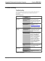
Problem Solving......................................................................................................................52
Troubleshooting.........................................................................................................52
Check Network Wiring..............................................................................................53
Reference Documents................................................................................................54
Further Inquiries........................................................................................................54
Future Updates ..........................................................................................................54
Appendix A: Programming Software ......................................................................................55
Earliest Version Software Requirements for the PC .................................................55
Programming with D3 Pro.........................................................................................55
Programming with SIMPL Windows........................................................................56
Programming with VisionTools Pro-e.......................................................................56
Default Program........................................................................................................57
Example Program......................................................................................................57
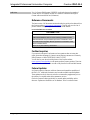
Appendix B: Uploading and Upgrading ..................................................................................58
Establishing Communication.....................................................................................58
Programs, Projects and Firmware..............................................................................59
Appendix C: Specifications.....................................................................................................60
Return and Warranty Policies..................................................................................................62
Merchandise Returns / Repair Service ......................................................................64
CRESTRON Limited Warranty.................................................................................64


Crestron IPAC-GL1 Integrated Professional Automation Computer
Integrated Professional
Automation Computer: IPAC-GL1
Introduction
This document provides instructions for commissioning a Crestron Green Light™
lighting system using an IPAC-GL1.
The IPAC-GL1 (IPAC) is a lighting control system that can switch up to 210 lighting
loads, monitor 81 occupancy sensors (or on/off photocells), and can be controlled by
up to 16 external keypads.
NOTE: This guide describes the functionality of the IPAC as shipped from the
factory using the default program. Extensive customization is possible using
Crestron programming tools. For more information, refer to “Appendix A:
Programming Software” on page 55 or contact Crestron at 1-888-CRESTRON
[1-888-273-7876] for more information.
Physical Description
This section provides information on the connections, controls, and indicators
available on your IPAC.
IPAC-GL1 Physical View (shown in black)
Setup Guide – DOC. 6660B Integrated Professional Automation Computer: IPAC-GL1 • 1

Integrated Professional Automation Computer Crestron IPAC-GL1
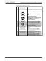
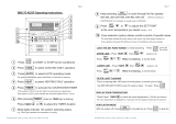
IPAC-GL1 Buttons & Ports
Connectors, Controls & Indicators
# CONNECTORS,
CONTROLS &
INDICATORS
DESCRIPTION
1
LIQUID CRYSTAL
DISPLAY
The Liquid Crystal Display (LCD) shows
system information such as lighting controls
and system status.
2 SOFT BUTTONS
The functions of the soft buttons are
dependent on which “page” the display is
currently showing. Labels will appear above
each button indicating their current function.
3 FUNCTION BUTTONS
(7) Programmable pushbuttons with backlit
labeling and LED feedback. Referred to as
the front panel keypad.
4 ENTER BUTTON
ENTER button performs the “default” action
for the current page.
5 SELECTION KNOB
(1) Continuous turn rotary encoder, used for
on-screen navigation.
6 LIGHT SENSOR
Photosensor, used for auto-adjustment of
function label backlight.
7
INFRARED (IR)
RECEIVER
Not used in the default program but can be
used in a custom program. Refer to “Appendix
A: Programming Software” on page 55 for
more information.
(Continued on following page)
2 • Integrated Professional Automation Computer: IPAC-GL1 Setup Guide – DOC. 6660B

Crestron IPAC-GL1 Integrated Professional Automation Computer
Connectors, Controls & Indicators (Continued)
# CONNECTORS,
CONTROLS &
INDICATORS
DESCRIPTION
8
NAVIGATION
BUTTONS
(4) Pushbuttons for navigating the IPAC
configuration menus.
HOME: Returns the display to the IPAC home
page.
BACK: Returns to the previously displayed
page.
CANCEL: Cancels certain operations without
committing them permanently.
HELP: Opens a context-sensitive help screen.
Pressing HELP again will return to the
previously displayed page.
9 USB PORT
(1) USB Type B female; USB 1.1 computer
console port (cable not included); Hidden
behind removable faceplate. Used for
uploading and upgrading. For more
information, refer to “Appendix B: Uploading
and Upgrading” on page 58.
10
SOFTWARE RESET
BUTTON (SW-R)
(Hidden behind
removable faceplate)
Pressing this button momentarily restarts the
program.
Pressing this in combination with HW-R
button performs a system restart without
loading the default program.
11
HARDWARE RESET
BUTTON (HW-R)
Pressing this button momentarily initiates a
system hardware reset.
Pressing this in combination with SW-R
button performs a system restart without
loading the default program.
Setup Guide – DOC. 6660B Integrated Professional Automation Computer: IPAC-GL1 • 3

Integrated Professional Automation Computer Crestron IPAC-GL1
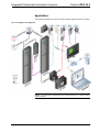
Applications
The following diagram shows an IPAC used to manage lighting controls in a facility.
IPAC in a Lighting Control Application
NOTE: For information on integration with Crestron RoomView
®
software, please
contact Crestron.
4 • Integrated Professional Automation Computer: IPAC-GL1 Setup Guide – DOC. 6660B

Crestron IPAC-GL1 Integrated Professional Automation Computer
Setup
Installation
For installation instructions, refer to the latest version of the IPAC Installation Guide
(Doc. 6696) which shipped with your IPAC and is also available for download from
the Crestron website (
www.crestron.com/manuals).
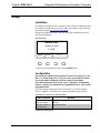
After power is applied to the IPAC, the IPAC home page is displayed as shown in
the following illustration.
IPAC Home Page
Setup Guide – DOC. 6660B Integrated Professional Automation Computer: IPAC-GL1 • 5
To return to the home page at any time, press the HOME button.
Configuration
The instructions contained in this document are written for version 1.2.1 of the
IPAC-GL1 Default Program. To verify your version, press the HOME button.
The version number is displayed in the lower-right part of the display.
If the default program is not to be used, refer to “Appendix A: Programming
Software” on page 55 for information on programming the IPAC with Crestron
programming tools.
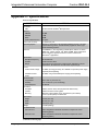
The following table lists the specifications for the IPAC-GL1 Default Program.
Refer to “Appendix C: Specifications” on page 60 for additional specifications.
Specifications for the IPAC-GL1 Default Program
SPECIFICATION DETAILS
Maximum number of
supported panels
9 GLEP enclosures with GLXP Power Switching
Modules
Maximum number of
controlled loads
210 switched loads
(Continued on following page)
Setup TmClk
Crestron IPAC
Octobe
r
20, 2009
20
4: PM
V1.2.1

Integrated Professional Automation Computer Crestron IPAC-GL1
6 • Integrated Professional Automation Computer: IPAC-GL1 Setup Guide – DOC. 6660B
Specifications for the IPAC-GL1 Default Program (Continued)
SPECIFICATION DETAILS
Keypads 16 external (max.) using any of the following keypads:
• CNX-B2, -B4, B6, B8, B12
• C2N-DB6, DB-8, DB-12
• C2N-CBF-*-T, -*-S
1 Internal Keypad
Timeclock 100 events
Sensors
Up to 40 sensors supported via GLS-SIM Sensor
Integration Modules. GLS-O* sensors recommended.
Up to 40 sensors supported via DIN-IO8 DIN Rail
Versiport Module. GLS-O* sensors recommended.
1 sensor via local input on the IPAC’s INPUTS port.
For additional information, refer to the latest version of the IPAC Installation Guide
(Doc. 6696) which shipped with your IPAC and is also available for download from
the Crestron website.
Prior to operation, the IPAC must be configured for use. When configuring the
system, it is important to have the following information:
• The total number of switching panels in the system and how many loads are
wired to each panel. For a description of a panel, refer to “Panels” on page
12.
• The lighting load schedule (i.e. which lighting loads are wired to which
panels, and which outputs within each panel).
• The total number and location of all external keypads in the system.
• The desired function for all keypad buttons, including the local buttons on
the IPAC itself.
• The total number and location of all occupancy sensors (or on/off
photocells).
• The desired timeclock functionality.
Worksheets for specifying switching panels, timeclock events, keypad locations,
button functions, and sensor locations are provided in the latest version of the
IPAC-GL1 System Planning Worksheets (Doc. 6784) which can be downloaded
from the Crestron website. Make copies as required and leave for the customer after
system installation has been completed.
Automated Functions
The IPAC will automatically perform specific functions when devices connected to
the INPUTS port are activated. The following table illustrates the input number and
its associated function.
INPUTS Port and Associate Functions
INPUT # FUNCTION DESCRIPTION
1 Sensor Input
Associated function is configured as described in
“Sensors” on page 39.
(Continued on following page)

Crestron IPAC-GL1 Integrated Professional Automation Computer
INPUTS Port and Associate Functions (Continued)
INPUT # FUNCTION DESCRIPTION
2 Enter Override mode
The system will enter the Override mode when a
device connected to this port provides a dry contact
closure to ground.
3 Lock IPAC
The front panel of the IPAC will be locked when a
device connected to this port provides a dry contact
closure to ground.
4 Lock Keypads
External keypads will be locked when a device
connected to this port provides a dry contact closure
to ground.
For information on wiring the INPUTS port, refer to the latest version of the IPAC
Installation Guide (Doc. 6696) which shipped with your IPAC and is also available
for download from the Crestron website.
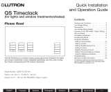
Introduction
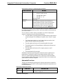
Use the front panel controls and display to configure the IPAC. The following
controls are used to navigate the front panel display:
• Selection Knob – Turn the selection knob to select the desired option. The
selected option is underlined.
• ENTER Button – Press the ENTER button to select an underlined item or
to store a setting. The ENTER button can also be used to activate a
highlighted soft button function.
• Soft Buttons – Soft buttons perform functions that are listed above them on
the front panel display.
• HOME Button – Press the HOME button to return to the IPAC home page.
If changes were made to the configuration, you will be asked to save
changes.
• BACK Button – Press the BACK button to return to the previous screen.
• CANCEL Button – Press the CANCEL button to cancel the current action.
• HELP Button – Press the HELP button at any time to open the online help
feature. Press again to close the online help.
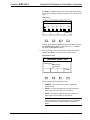
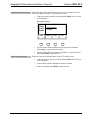
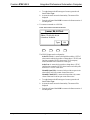
The display is used to show available options and a variety of information during the
configuration process. Title screens are shown at the top or side of the display.
Configuration options and data are displayed in the center of the display, and
available functions for the soft buttons are located along the bottom of the display.
Soft button functions that are highlighted can be activated by pressing the associated
soft button or the ENTER button.
Display
Copy Paste Next
Button 1
Button 2 (empty)
Button 3 (empty)
Button 4 (empty)
Select
Btn
KP-0
SelectEdit
Highlighted
Function
Setup Guide – DOC. 6660B Integrated Professional Automation Computer: IPAC-GL1 • 7

Integrated Professional Automation Computer Crestron IPAC-GL1
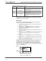
Setup Menu
For Unconfigured Systems
(First time use only)
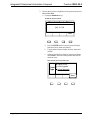
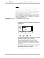
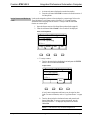
If the system has not been configured, the IPAC will display the Setup Menu.
For Configured Systems
If a system has already been configured, the Setup Menu can be opened from the
IPAC home page. To open the Setup Menu:
• Press the HOME button.
• Press the soft button labeled Setup.
Setup Menu
Select
Project Settings
Panels
Keypads
Timeclock
Setup
Select
The Setup Menu is broken down into eight sections:
• Project Settings – Sets the geographical location of the IPAC installation
as well as the time, date, and Daylight Savings Time mode.
• Panels – Configures lighting loads controlled by the IPAC.
• Keypads – Configures the front panel function buttons and all external
keypads installed in the IPAC system.
• Timeclock – Configures the IPAC’s timeclock.
• Sensors – Configures operation of sensors connected to the IPAC.
• Password – Sets the front panel password.
• Ethernet Settings – Configures the IPAC’s Ethernet settings.
• About – Displays information about the IPAC.
To select an item to configure, turn the selection knob to highlight the desired section
and press the ENTER button or the soft button labeled Select.
8 • Integrated Professional Automation Computer: IPAC-GL1 Setup Guide – DOC. 6660B

Crestron IPAC-GL1 Integrated Professional Automation Computer
Project Settings
The IPAC uses state and city location information to determine latitude and
longitude for its astronomical clock. Refer to the completed “Project Settings
Worksheet” in the latest version of the IPAC-GL1 System Planning Worksheets
when entering settings.
Open Project Settings
To open the Project Settings section of the Setup Menu:
1. Turn the selection knob to highlight Project Settings.
2. Press ENTER or the soft button labeled Select to open the Project Settings
section of the Setup Menu.
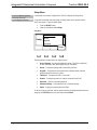
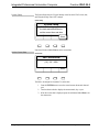
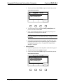
Select the State
To identify the local time zone, select the state where the IPAC is installed. To select
the state:
1. Turn the selection knob to highlight the state where the IPAC is installed.
2. Press ENTER or the soft button labeled Next to select the highlighted state.
Select the State
Next
New Jersey
New Mexico
New York
North Carolina
Select
State
SelectNext
Select the City
To further identify the locality, select the city nearest the IPAC installation. To select
a city:
1. Turn the selection knob to highlight a city near the IPAC installation.
2. Press ENTER or the soft button labeled Next to select the highlighted city.
Select the City
Next
Newburgh
New York City
Niagara Falls
Olean
Select
State
SelectNext
Setup Guide – DOC. 6660B Integrated Professional Automation Computer: IPAC-GL1 • 9

Integrated Professional Automation Computer Crestron IPAC-GL1
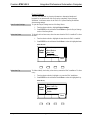
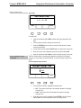
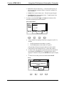
System Setup
The System Setup section of Project Settings is used to set the IPAC’s time, date,
and Daylight Savings Time (DST) settings.
System Setup
Next
System Setup
On the following pages use
the knob and enter button to
set the current time and date
SelectNext
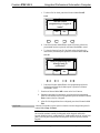
Press the soft button labeled Next to set the current date.
Set the Current Date
Set the Date
Next
Set Current Date
[10] – 20 – 2008
The field to be changed is in brackets. To set the date:
1. Press the ENTER button to move the cursor between the month, date and
year.
2. Turn the selection knob to display the current month, day, or year.
3. When the correct date is displayed, press the soft button labeled Next to set
the current time.
10 • Integrated Professional Automation Computer: IPAC-GL1 Setup Guide – DOC. 6660B

Crestron IPAC-GL1 Integrated Professional Automation Computer
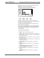
Set the Current Time
Set the Time
Edit Next
Set Current Time
4 : 21 : 08 PM
To set the time:
1. Press the soft button labeled Edit. Brackets will appear around the hour
digit.
2. Turn the selection knob to display the current hour.
3. Press the ENTER button to move the cursor between the hour, minute,
seconds, and AM/PM.
4. Use the selection knob and the ENTER button to display the current time.
5. When the correct time is displayed, press the soft button labeled Set.
6. Press the soft button labeled Next to set the Daylight Savings Time mode.
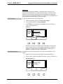
Set the Daylight Savings
Time Mode
The IPAC has the ability to automatically adjust the system clock for daylight
savings time. This feature can also be disabled. To set the Daylight Savings Time
mode:
Set the Daylight Savings Time Mode
Next
Daylight Savings Time
Off
Auto
SelectExit
1. Turn the selection knob to highlight the desired mode.
⇒ Off – The system clock needs to be manually adjusted for Daylight
Savings Time.
⇒ Auto – The system clock will automatically adjust for Daylight
Savings Time.
2. When the correct mode is highlighted, press ENTER or the soft button
labeled Exit to save the settings and return to the Setup Menu.
Setup Guide – DOC. 6660B Integrated Professional Automation Computer: IPAC-GL1 • 11

Integrated Professional Automation Computer Crestron IPAC-GL1
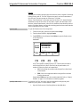
Panels
The term panel is used to describe a physical enclosure which is capable of switching
lighting loads on and off. The IPAC supports nine panels, each with a maximum of
up to 42 loads. The entire system can contain up to 210 loads.
Use the “Panel Worksheet” in the latest version of the IPAC-GL1 System Planning
Worksheets to map out the location of each load in a panel, their associated “warn”
functions, and associated sensors. After all of the loads have been identified, use this
section of the Setup Menu to configure the switching panels and associated loads that
will be controlled by the IPAC system.
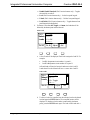
Open Panels
To open the Panels section of the Setup Menu:
1. From the home page, press the soft button labeled Setup.
2. Turn the selection knob to highlight Panels.
3. Press ENTER or the soft button labeled Select to open the Panels section
of the Setup Menu.
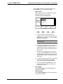
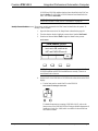
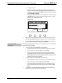
Load Count
Edit Clear ID Exit
1: 24 Loads ERR
2: 42 Loads OK
3: 24 Loads OK
4: --- ---
Load
Count
SelectEdit
A list of nine panels is displayed on the LCD. Turn the selection knob to
scroll through the list of panels. Each line lists the panel number, the
number of loads in the panel, and a status label:
• OK: Indicates that the modules inside the panel have been found
on the network.
• ERR: One or more required modules in the panel have not been
found on the network.
Panels labeled ERR must have their modules identified. Refer to “Identify
Modules” on page 13 for information on identifying panels.
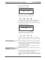
Specify Load Count
You must tell the IPAC how many loads are terminated in each physical panel
installed in your system. To set the number of loads:
1. Open the Panels section of the Setup Menu as described above.
12 • Integrated Professional Automation Computer: IPAC-GL1 Setup Guide – DOC. 6660B

Crestron IPAC-GL1 Integrated Professional Automation Computer
2. Turn the selection knob to the desired panel and press the ENTER button or
the soft button labeled Edit.
Set the Number of Loads
Set
1: [24] Loads
2: --- ---
3: --- ---
4: --- ---
Load
Count
SelectSet
3. Turn the selection knob until the desired load count is displayed.
4. Press the ENTER button or the soft button labeled Set.
5. Repeat for every panel in the system.
Clear a Panel
To remove a panel from the system:
1. Open the Panels section of the Setup Menu as described on page 12.
2. Turn the selection knob to highlight the panel to be cleared and press the
soft button labeled Clear. Alternately, you can manually adjust the load
count of a panel to 0 (zero). This will have the same effect as pressing
Clear.
NOTE: If only one panel is listed, it cannot be cleared.
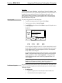
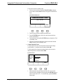
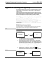
Identify Modules
Each load in a panel is switched on and off by a lighting module installed in the
panel. To properly control the loads in a system, the modules to which they are
connected must be identified to the IPAC. To identify modules:
1. Open the Panels section of the Setup Menu as described on page 12.
2. Turn the selection knob to highlight the panel to be identified.
3. Press the soft button labeled ID.
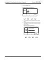
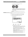
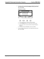
Identify Modules
OK
OK
OK
ERR
---
Set Module ID’s
in PNL-2 to these
values:
21
22
23
24
SelectOK
Setup Guide – DOC. 6660B Integrated Professional Automation Computer: IPAC-GL1 • 13

Integrated Professional Automation Computer Crestron IPAC-GL1
14 • Integrated Professional Automation Computer: IPAC-GL1 Setup Guide – DOC. 6660B
The IPAC will show a graphic which represents a panel and four modules
installed within it, ranging from top to bottom. Note that many panels will
have less than four modules installed, but none will have more than four.
Inside the boxes representing the modules will be 2-digit ID codes. These
indicate the Module ID that each module must be set to in order to work
properly.
Next to each module in the display is a label: OK (a module at this ID has
been found on the network), ERR (no module at this ID has been found), or
--- (this panel already has enough modules defined to satisfy the load
count).
4. Set the Module ID of each module in a panel to the number specified on the
display. For information on setting Module IDs, refer to the latest version of
the CRESTRON GREEN LIGHT™ Power Switching Installation Guide
(Doc. 6672) which was shipped with the panel, and is available for
download from the Crestron website.
NOTE: Care must be taken to ensure that no two modules in the system
share the same Module ID. This situation will cause unpredictable behavior.
Additionally, a module with a Module ID outside of the specified value
may conflict with other devices in the system.
After the Module ID is set correctly, the module label will change from
ERR to OK.
5. After all of the modules in a panel have been identified, press the soft
button labeled OK or press the ENTER button to return to the panel list.
6. Repeat the identification process for each panel in the system.
7. After all of the panels have been configured and identified, press the soft
button labeled EXIT to save the settings and return to the Setup Menu.

Crestron IPAC-GL1 Integrated Professional Automation Computer
Keypads
Use the “Keypad Location Worksheet” and the “Button Function Worksheet” in the
latest version of the IPAC-GL1 System Planning Worksheets to map out locations of
keypads in the system and the function(s) of each button in the system. After
specifying the location and function of each keypad and button, use this section of
the Setup Menu to configure the front panel keypad and up to 16 external keypads
that can control the IPAC system.
Open Keypads
To open the Keypads section of the Setup Menu:
1. From the home page, press the soft button labeled Setup.
2. Turn the selection knob to highlight Keypads.
3. Press ENTER or the soft button labeled Select to open the Keypads section
of the Setup Menu.
Keypad List
Auto Edit Find Exit
0: Online
1: Not Programmed
2: Not Found
3: Not Found
Keypd
List
SelectEdit
A list of keypads is displayed on the LCD. Turn the selection knob to scroll
through the list of keypads. Each line lists the keypad number and its status.
Keypad 0 represents the front panel keypad on the IPAC while keypads 1
through 16 are external keypads.
If an external keypad has not been found on the network, it is listed as Not
Found. If a keypad has been identified, but no buttons on the keypad have
been programmed, it is listed as Not Programmed. If a keypad has been
found on the network and contains at least one programmed button, it is
listed as Online.
NOTE: If a keypad is attached to the network, but is still listed as Not
Found even after attempts to identify it, detach it from the network
temporarily to allow the rest of the keypads to work properly.
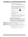
Find External Keypads
Each external keypad connected to the IPAC must be identified to the system before
it will be recognized. Keypads can be identified by button press or by serial number.
To identify a keypad:
• By button press:
1. Open the Keypads section of the Setup Menu as described above.
2. Turn the selection knob to highlight a keypad.
Setup Guide – DOC. 6660B Integrated Professional Automation Computer: IPAC-GL1 • 15

Integrated Professional Automation Computer Crestron IPAC-GL1
3. Press the soft button labeled Find to begin the identification process.
Select Identification Method
Next
Keypad – Set ID
Find by pressing button
Find by entering S/N
SelectNext
4. Turn the selection knob to highlight Find by pressing button and
press the soft button labeled Next.
5. Every connected keypad will flash. The display will prompt you to
press a button on the keypad to be identified.
NOTE: If a keypad does not flash, verify that it is properly connected
to the network. Refer to “Check Network Wiring” on page 53 for more
information.
6. Press a button on the keypad to be identified. The display will show
programming information for the identified keypad. For information
on keypad programming, refer to “Program/Edit a Keypad Button
Manually” on page 20.
• By Serial Number:
1. Open the Keypads section of the Setup Menu as described on page 15.
2. Turn the selection knob to highlight a keypad.
3. Press the soft button labeled Find to begin the identification process.
Select Identification Method
Next
Keypad – Set ID
Find by pressing button
Find by entering S/N
SelectNext
16 • Integrated Professional Automation Computer: IPAC-GL1 Setup Guide – DOC. 6660B
Page is loading ...
Page is loading ...
Page is loading ...
Page is loading ...
Page is loading ...
Page is loading ...
Page is loading ...
Page is loading ...
Page is loading ...
Page is loading ...
Page is loading ...
Page is loading ...
Page is loading ...
Page is loading ...
Page is loading ...
Page is loading ...
Page is loading ...
Page is loading ...
Page is loading ...
Page is loading ...
Page is loading ...
Page is loading ...
Page is loading ...
Page is loading ...
Page is loading ...
Page is loading ...
Page is loading ...
Page is loading ...
Page is loading ...
Page is loading ...
Page is loading ...
Page is loading ...
Page is loading ...
Page is loading ...
Page is loading ...
Page is loading ...
Page is loading ...
Page is loading ...
Page is loading ...
Page is loading ...
Page is loading ...
Page is loading ...
Page is loading ...
Page is loading ...
Page is loading ...
Page is loading ...
Page is loading ...
Page is loading ...
Page is loading ...
Page is loading ...
-
 1
1
-
 2
2
-
 3
3
-
 4
4
-
 5
5
-
 6
6
-
 7
7
-
 8
8
-
 9
9
-
 10
10
-
 11
11
-
 12
12
-
 13
13
-
 14
14
-
 15
15
-
 16
16
-
 17
17
-
 18
18
-
 19
19
-
 20
20
-
 21
21
-
 22
22
-
 23
23
-
 24
24
-
 25
25
-
 26
26
-
 27
27
-
 28
28
-
 29
29
-
 30
30
-
 31
31
-
 32
32
-
 33
33
-
 34
34
-
 35
35
-
 36
36
-
 37
37
-
 38
38
-
 39
39
-
 40
40
-
 41
41
-
 42
42
-
 43
43
-
 44
44
-
 45
45
-
 46
46
-
 47
47
-
 48
48
-
 49
49
-
 50
50
-
 51
51
-
 52
52
-
 53
53
-
 54
54
-
 55
55
-
 56
56
-
 57
57
-
 58
58
-
 59
59
-
 60
60
-
 61
61
-
 62
62
-
 63
63
-
 64
64
-
 65
65
-
 66
66
-
 67
67
-
 68
68
-
 69
69
-
 70
70


Ask a question and I''ll find the answer in the document
Finding information in a document is now easier with AI
Related papers
-
Crestron IPAC User manual
-
-
Crestron DIN-PWS50 User guide
-
-
-
-
-
-
-
Other documents
-
 Crestron electronic GLS-LCL User manual
-
 Crestron electronic GLS-OIR-C-450/1500 User manual
-
 Crestron electronic GLA-PWS50 User manual
-
 Calculated Industries 6260 User manual
-
 Adp Series 4000 Installation guide
-
 Crestron electronic GLS-ODT-W-1200 User manual
-
 ActronControls Leasam BM2-7D-4Z Operating instructions
-
 Crestron electronic GLS-ODT-C-500. GLS-ODT-C-1000 User manual
-
Control4 Nurture User guide
-
 Lutron Electronics QSGR-TC-3S-WH Quick Installation And Operation Manual


