Page is loading ...

GLS-SIM
Sensor Integration Module
Installation and Operation Guide
Description
The GLS-SIM is a compact interface device designed to allow Crestron Green Light
®
sensors to be connected directly to a Cresnet
®
control network. Cresnet is the
communications backbone for Crestron
®
sensors, dimmers, keypads, touchpanels,
shade controllers, thermostats, and many other devices. This exible 4-wire bus provides
data communications and 24 Vdc power for all of the devices on the Cresnet network.
The GLS-SIM installs easily at the sensor location, mounting inside the electrical box or
exposed above the ceiling. Wiring connections to the network and sensor are facilitated
using miniature screw terminals.
GLS-SIM Specications
Identity Code
The Net ID of the GLS-SIM has been factory set to 92 (with a mechanical setting of 00).
NOTE: The ID CODE switches on the GLS-SIM are factory set to 00. This allows
changing the Net ID with Crestron Toolbox™ software (optional).
The Net ID of the GLS-SIM can be set using one of two methods:
• Manual Setting: Set the two ID CODE switches (from 03 to FE) to match a Net ID in
the SIMPL Windows program.
• Touch-settable ID: Set the two ID CODE switches to 00 and set the Net ID using
Crestron Toolbox. This is the factory setting. For more details, refer to the Crestron
Toolbox help le.
ID CODE Switches
Additional Resources
Visit the product page on the Crestron website (www.crestron.com)
for additional information and the latest rmware updates. Use a QR
reader application on your mobile device to scan the QR image.
Hardware Hookup
Make the necessary connections as called out in the illustration. Apply power after all
connections have been made.
CAUTION: Insufcient power can lead to unpredictable results or damage to the
equipment. To help calculate how much power is needed for the system, use the
Crestron Power Calculator at www.crestron.com/calculators.
NOTE: Use Crestron Certied Wire.
NOTE: When making connections, strip the ends of the wires approximately 1/2 in
(13 mm). Use care to avoid nicking the conductors. Twist together the ends of the
wires that share a connection.
GLS-SIM Connections
NOTE: The SENSOR port is a 4-pin 3.5 mm detachable terminal block. The sensor
input is comprised of 24 Vdc power output and two Versiports (referenced to GND),
5 V and 2k ohms pull-up resistor per pin.
NOTE: Depending on the available Cresnet power, the GLS-SIM can pass a maximum
of 1 A @ 24 Vdc to the devices or sensors that are connected to the SENSOR port.
Other Connections
The GLS-SIM can be congured as a digital input, an analog input, or a digital output.
This setting is determined by the program running in the attached control processor.
Other settings are controlled by the DIP switches. Refer to the “Conguration” section for
diagrams that show how the GLS-SIM should be wired for each application.
CAUTION: Incorrect wiring may damage the GLS-SIM.
When setting the Net ID, consider the following:
• The Net ID of each unit must match an ID code specied in the control system
program.
• Each network device must have a unique Net ID.
Installation
NOTE: Observe the following points.
• Install and use this product in accordance with appropriate electrical codes and
regulations.
• If unsure about any part of these instructions, consult a qualied electrician.
• Mount the sensor on a vibration-free surface.
• All sensors must be mounted at least 6 feet (1.8 m) away from air vents.
• Do not mount sensors closer than 10 feet (3 m) from each other.
• Do not touch the inner surface of the lens. Clean outer surface with a damp cloth
only.
NOTE: Before using the GLS-SIM, ensure the device is using the latest rmware.
Check for the latest rmware for the GLS-SIM at www.crestron.com/rmware. Load
rmware onto the device using Crestron Toolbox software.
The GLS-SIM can be installed inside a standard 4-inch electrical box or mounted above
the ceiling using the included mounting bracket or the included dual-lock fastener. Use a
#1 Phillips screwdriver and the included screws to attach the included mounting bracket.
Attaching the Mounting Bracket to GLS-SIM (Optional)
NOTE: Screws used for securing the GLS-SIM to a surface are not included.
Using a Dual-Lock Fastener on the GLS-SIM (Optional)
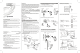
Mounting in an Octagon Back Box Installed Flush to a Drop Ceiling
2.88 in
(74 mm)
2.48 in
(63 mm)
0.20 in
(6 mm)
Drop ceiling
Octagon back box
4 in x 1-1/2 in deep
#8-32 screws
(2 places)
GLS-SIM
Low-voltage
wires
SENSOR:
Sends power to
and receives input
from sensor(s)
NET:
To control system
and other Cresnet
devices
Conguration
Use the DIP switches to congure the GLS-SIM to work with various device types, as
described in the following illustrations and associated tables.
DIP Switches on GLS-SIM
1 2 3 4
On
Off
Sensor Digital Input
The GLS-SIM can be congured for sensors that use relay contacts (normally open or
normally closed) or voltage level (active high or active low). The digital input is rated for
0–24 Vdc, the input impedance is 18.5k ohms, and the logic threshold is 1.25 Vdc.
Refer to the tables and wiring diagrams to congure the GLS-SIM.
Switch Settings for Digital Input (Dry Contact Closure)
SENSOR
24 1 2 G
Detecting a
contact
closure from
a switch or
relay
Detecting
a low
voltage
24 Vdc
max.
SENSOR
24 1 2 G
Switch Settings for Digital Input (Voltage Detection)
SPECIFICATION DETAILS
Power Requirements
Cresnet Power Usage 1 W (0.04 A @ 24 Vdc)
(Does not include power draw of attached devices.)
Environmental
Temperature 32° to 104 °F (0° to 40 °C)
Humidity 0% to 95% RH (noncondensing)
Dimensions
Height 2.00 in (51 mm)
Width 2.00 in (51 mm)
Depth 0.86 in (22 mm)
Weight 2 oz (57 g)
INPUT
CHANNEL
DIP
SWITCH
SETTING
1
1 OFF: Enables pull-up resistor
ON: Disables pull-up resistor
2 OFF: Normal polarity
ON: Inverted polarity
2
3 OFF: Enables pull-up resistor
ON: Disables pull-up resistor
4 OFF: Normal polarity
ON: Inverted polarity
INPUT
CHANNEL
DIP
SWITCH
SETTING
1
1 OFF
2 OFF: Normally open
ON: Normally closed
2
3 OFF
4 OFF: Normally open
ON: Normally closed
INPUT
CHANNEL
DIP
SWITCH
SETTING
1
1 ON
2 OFF: Active low
ON: Active high
2
3 ON
4 OFF: Active low
ON: Active high

* Setting switches 2 or 4 to ON inverts the polarity, causing the
control signal to read “100%” at 0 V and “0%” at 10 V.
This product is Listed to applicable UL
®
Standards and requirements by Underwriters Laboratories
Inc.
Ce produit est homologué selon les normes et les exigences UL applicables par Underwriters
Laboratories Inc.
Suitable for use in environmental air space in accordance with Section 300-22(c) of the National
Electrical Code (US, NFPA-70), and Sections 2-128, 12-010(3), and 12-100 of the Canadian
Electrical Code, Part 1, CSA C22.1.
As of the date of manufacture, the device has been tested and found to comply with specications
for CE marking.
Federal Communications Commission (FCC) Compliance Statement
This device complies with part 15 of the FCC Rules. Operation is subject to the following
conditions:(1) This device may not cause harmful interference and (2) this device must accept any
interference received, including interference that may cause undesired operation.
Troubleshooting
The following table provides corrective actions for possible trouble situations. If further
assistance is required, please contact a Crestron customer service representative.
NOTE: When troubleshooting, keep in mind that operation is ultimately determined by
the control system program.
Crestron Electronics, Inc. Installation & Operation Guide - DOC. 6768C
15 Volvo Drive Rockleigh, NJ 07647 (2022952)
Tel: 888.CRESTRON 12.16
Fax: 201.767.7576 Specications subject to
www.crestron.com change without notice.
CAUTION: Changes or modications not expressly approved by the manufacturer responsible for
compliance could void the user’s authority to operate the equipment.
NOTE: This equipment has been tested and found to comply with the limits for a Class B digital device,
pursuant to part 15 of the FCC Rules. These limits are designed to provide reasonable protection
against harmful interference in a residential installation. This equipment generates, uses and can radiate
radio frequency energy and, if not installed and used in accordance with the instructions, may cause
harmful interference to radio communications. However, there is no guarantee that interference will not
occur in a particular installation. If this equipment does cause harmful interference to radio or television
reception, which can be determined by turning the equipment off and on, the user is encouraged to try
to correct the interference by one or more of the following measures:
• Reorient or relocate the receiving antenna.
• Increase the separation between the equipment and receiver.
• Connect the equipment into an outlet on a circuit different from that to which the receiver is
connected.
• Consult the dealer or an experienced radio/TV technician for help.
The product warranty can be found at www.crestron.com/warranty.
The specic patents that cover Crestron products are listed at patents.crestron.com.
Certain Crestron products contain open source software. For specic information, please visit
www.crestron.com/opensource.
Crestron, the Crestron logo, Crestron Green Light, Cresnet, and Crestron Toolbox are either trademarks
or registered trademarks of Crestron Electronics, Inc. in the United States and/or other countries. UL
and the UL logo are either trademarks or registered trademarks of Underwriters Laboratories, Inc. in the
United States and/or other countries. Other trademarks, registered trademarks, and trade names may
be used in this document to refer to either the entities claiming the marks and names or their products.
Crestron disclaims any proprietary interest in the marks and names of others. Crestron is not
responsible for errors in typography or photography.
This document was written by the Technical Publications department at Crestron.
©2016 Crestron Electronics, Inc.
Switch Settings for Digital Input
(Crestron occupancy sensors, e.g., GLS-ODT-C500/1000/2000)
Analog Input
When using the GLS-SIM to read an analog input, set the DIP switches as shown in the
tables and wiring diagrams to congure the GLS-SIM. The analog input is rated for
0–10 Vdc, protected to a maximum of 24 Vdc, and the input impedance is 18.5k ohms.
Switch Settings for Analog Input (Read Voltage from Analog Source)
Switch Settings for Analog Input (Crestron Photocells, e.g., GLS-LCL and GLS-LOL)
Switch Settings for Analog Input (Read Resistance of Potentiometer)
Digital Output
When using the GLS-SIM as a digital output, set the DIP switches as shown in the table
and wiring diagram. The digital output is a 250mA sink from a maximum of 24 Vdc, and
catch diodes are used with “real world” loads.
Switch Settings for Digital Output (Drive a Relay Coil)
SENSOR
24 1 2 G
GLS-SIM
GLS-ODT-C
Sensor
Red
Black
Blue
INPUT
CHANNEL
DIP
SWITCH
SETTING
1
1 ON
2 ON
2
3 ON
4 ON
SENSOR
24 1 2 G
10 Vdc
Reading a
voltage from an
analog source
INPUT
CHANNEL
DIP
SWITCH
SETTING
1
1 ON
2 OFF*
2
3 ON
4 OFF*
* Setting switches 2 or 4 to ON inverts the polarity, causing the
control signal to read “100%” at 0 V and “0%” at 10 V.
SENSOR
24 1 2 G
GLS-SIM
Orange
GLS-LCL
Red
Black
INPUT
CHANNEL
DIP
SWITCH
SETTING
1
1 ON
2 OFF*
2
3 ON
4 OFF*
SENSOR
24 1 2 G
Reading the
resistance of a
potentiometer
INPUT
CHANNEL
DIP
SWITCH
SETTING
1
1 OFF
2 OFF*
2
3 OFF
4 OFF*
SENSOR
24 1 2 G
Driving a
relay coil
24 Vdc
max.
INPUT
CHANNEL
DIP
SWITCH
SETTING
1
1 ON
2 OFF*
2
3 ON
4 OFF*
TROUBLE POSSIBLE CAUSE(S) CORRECTIVE ACTION
The device does not
turn on (PWR LED is not
lit).
The device is not
receiving power from a
Crestron power source.
Use the provided
Crestron power
source. Verify that the
connections are
correct.
The device is not
receiving sufcient
power.
Use the Crestron
Power Calculator to
help calculate how
much power is needed
for the system.
There is electrostatic
discharge due to
improper grounding.
Check that all ground
connections have
been made properly.
The device does not
function as expected.
The unit is not
congured correctly.
Verify that the DIP
switch settings and
sensor wiring are
correct.
The programming in the
control system is
incorrect.
Check the control
system logic, or
contact Crestron for
assistance.
* Setting switches 2 or 4 to ON inverts the polarity, causing the
control signal to read “100%” at 0 V and “0%” at 10 V.
* Setting switches 2 or 4 to ON inverts the polarity, causing the
control signal to read “100%” at 0 V and “0%” at 10 V.
/