Crestron DIN-PWS50 User guide
- Category
- Power supply units
- Type
- User guide
This manual is also suitable for

Crestron DIN-BLOCK
DIN Rail Cresnet
®
Distribution Block
Operations & Installation Guide

This document was prepared and written by the Technical Documentation department at:
The specific patents that cover Crestron products are listed at patents.crestron.com.
Crestron, the Crestron logo, and Cresnet are either trademarks or registered trademarks of Crestron Electronics,
Inc. in the United States and/or other countries. UL and the UL logo are either trademarks or registered trademarks
of Underwriters Laboratories, Inc. in the United States and/or other countries. Other trademarks, registered
trademarks, and trade names may be used in this document to refer to either the entities claiming the marks and
names or their products. Crestron disclaims any proprietary interest in the marks and names of others.
©2012 Crestron Electronics, Inc.
Regulatory Compliance
This product is Listed to applicable UL Standards and requirements by Underwriters Laboratories Inc.
As of the date of manufacture, the DIN-BLOCK has been tested and found to comply with specifications for
CE marking and standards per EMC and Radiocommunications Compliance Labelling.

Crestron DIN-BLOCK DIN Rail Cresnet
®
Distribution Block
Operations & Installation Guide – DOC. 6670B Contents
•
i
Contents
DIN Rail Cresnet
®
Distribution Block: DIN-BLOCK 1
Introduction ............................................................................................................................... 1
Features and Functions ................................................................................................ 1
Applications................................................................................................................. 3
Specifications .............................................................................................................. 4
Physical Description .................................................................................................... 5
Setup .......................................................................................................................................... 8
Network Wiring ........................................................................................................... 8
Installation ................................................................................................................... 8
Hardware Hookup ..................................................................................................... 10
Problem Solving ...................................................................................................................... 11
Troubleshooting ......................................................................................................... 11
Y and Z LED Illumination ........................................................................................ 11
Check Network Wiring .............................................................................................. 12
Further Inquiries ........................................................................................................ 13
Future Updates .......................................................................................................... 14
Return and Warranty Policies .................................................................................................. 15
Merchandise Returns / Repair Service ...................................................................... 15
Crestron Limited Warranty ........................................................................................ 15


Crestron DIN-BLOCK DIN Rail Cresnet
®
Distribution Block
Operations & Installation Guide – DOC. 6670B DIN Rail Cresnet
®
Block: DIN-BLOCK
•
1
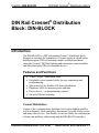
• 12 port Cresnet
®
distribution block
• Detachable screw terminal blocks for easy termination and
troubleshooting
• Split power bus for flexible 24V power distribution
• Diagnostic LEDs for network power and data
• Passive device – no programming required
• 6M wide DIN rail mounting
DIN Rail Cresnet
®
Distribution
Block: DIN-BLOCK
Introduction
The DIN-BLOCK is a DIN rail mounted Cresnet
®
distribution block
designed to facilitate the termination of Cresnet wiring at a head end or
distribution point. DIN rail mounting enables modular installation
alongside Crestron
®
DIN Rail lighting and automation control modules
and other third party DIN rail mountable devices.
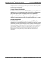
Features and Functions
Cresnet Distribution
Cresnet is the communications backbone for Crestron lighting modules,
wall box dimmers, shade controllers, thermostats, keypads, touch screens
and many other devices. This flexible 4-wire bus allows for combinations
of home run and daisy chain wiring and the DIN-BLOCK provides a

DIN Rail Cresnet
®
Distribution Block Crestron DIN-BLOCK
2
•
DIN Rail Cresnet
®
Block: DIN-BLOCK Operations & Installation Guide – DOC. 6670B
simple means for connecting up to 12 separate Cresnet cables in parallel
as part of any sized network.
Cresnet Power Distribution
In addition to data, Cresnet carries 24 Volts DC for powering the devices
connected to it. The Cresnet ports on the DIN-BLOCK are arranged into
two separate power groups, providing an easy way to manage the
distribution of power for a complete Cresnet network. A separate power
supply may be dedicated to each group or a single supply can be
connected to both groups as needed. Each group supports up to 75 Watts.
DIN Rail Installation
The DIN-BLOCK is designed to snap onto a standard DIN rail for
installation in a wall mount enclosure or mounted on a wall panel. Wiring
connections are made using detachable screw terminals positioned along
the top and bottom, clearly accessible from the front for easy installation
and servicing. Diagnostic indicators are positioned on the center front
panel. When installed in an enclosure utilizing 45 mm cutouts, the
DIN-BLOCK’s front panel stays visible while the connections are
concealed.

Crestron DIN-BLOCK DIN Rail Cresnet
®
Distribution Block
Operations & Installation Guide – DOC. 6670B DIN Rail Cresnet
®
Block: DIN-BLOCK
•
3
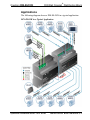
Applications
The following diagram shows a DIN-BLOCK in a typical application.
DIN-BLOCK in a Typical Application

DIN Rail Cresnet
®
Distribution Block Crestron DIN-BLOCK
4
•
DIN Rail Cresnet
®
Block: DIN-BLOCK Operations & Installation Guide – DOC. 6670B
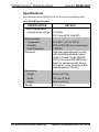
Specifications
Specifications for the DIN-BLOCK are listed in the following table.
DIN-BLOCK Specifications
SPECIFICATION DETAILS
Power Requirements
Cresnet Power Usage 0.3 Watts
(0.01 Amp @ 24 Volts DC)
Environmental
Temperature 0º to 40º C (32º to 104º F)
Humidity 10% to 90% RH (non-condensing)
Heat Dissipation 1 BTU/Hr
Enclosure Light gray polycarbonate housing
with polycarbonate label overlay,
UL94 V-0 rated, 35 mm DIN EN
60715 rail mount, DIN 43880 form
factor for enclosures with 45 mm
front panel cutout, occupies 6 DIN
module spaces (108 mm)
Dimensions
Height 95 mm (3.71 in)
Width 106 mm (4.18 in)
Depth 58 mm (2.29 in)
Weight 170 g (6 oz)

Crestron DIN-BLOCK DIN Rail Cresnet
®
Distribution Block
Operations & Installation Guide – DOC. 6670B DIN Rail Cresnet
®
Block: DIN-BLOCK
•
5
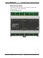
Physical Description
This section provides information on the connections, controls and
indicators available on the DIN-BLOCK.
DIN-BLOCK Physical View

DIN Rail Cresnet
®
Distribution Block Crestron DIN-BLOCK
6
•
DIN Rail Cresnet
®
Block: DIN-BLOCK Operations & Installation Guide – DOC. 6670B
DIN-BLOCK Overall Dimensions
58 mm
(2.29 in)
106 mm
(4.18 in)
95 mm
(3.71 in)
90 mm
(3.55 in)
2
3
4
1
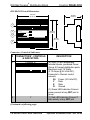
Connectors, Controls & Indicators
# CONNECTORS
1
, CONTROLS
& INDICATORS
DESCRIPTION
1 POWER A
2
(6) 4-pin 3.5 mm detachable
terminal blocks, paralleled Power
Group A Cresnet distribution ports;
Maximum load: 75 Watts
(3.13 Amps @ 24 Volts DC);
Connects to Cresnet control
network;
24: Power (24 Volts DC)
Y: Data
Z: Data
G: Ground
(1) Green LED indicates Cresnet
power present at any NET port in
group
2 Y (1) Red LED indicates Cresnet Y
data activity at any NET port
(Continued on following page)

Crestron DIN-BLOCK DIN Rail Cresnet
®
Distribution Block
Operations & Installation Guide – DOC. 6670B DIN Rail Cresnet
®
Block: DIN-BLOCK
•
7
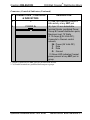
Connectors, Controls & Indicators (Continued)
# CONNECTORS
1
, CONTROLS
& INDICATORS
DESCRIPTION
3 Z (1) Red LED indicates Cresnet Z
data activity at any NET port
4 POWER B
2
(6) 4-pin 3.5 mm detachable
terminal blocks, paralleled Power
Group B Cresnet distribution ports;
Maximum load: 75 Watts
(3.13 Amps @ 24 Volts DC);
Connects to Cresnet control
network;
24: Power (24 Volts DC)
Y: Data
Z: Data
G: Ground
(1) Green LED indicates Cresnet
power present at any NET port in
group
1. Interface connectors for NET ports are provided with the unit.
2. Y, Z and G terminals are paralleled between power groups.

DIN Rail Cresnet
®
Distribution Block Crestron DIN-BLOCK
8
•
DIN Rail Cresnet
®
Block: DIN-BLOCK Operations & Installation Guide – DOC. 6670B
Setup
Network Wiring
When wiring the Cresnet network, consider the following:
• Use Crestron Certified Wire.
NOTE: Cresnet HP cannot be used.
• Use Crestron power supplies for Crestron equipment.
• Provide sufficient power to the system.
CAUTION: Insufficient power can lead to unpredictable results
or damage to the equipment. Use the Crestron Power Calculator to
help calculate how much power is needed for the system
(
www.crestron.com/calculators).
• Use of a Cresnet hub/repeater (DIN-HUB) is advised whenever the
number of Cresnet devices on a network exceeds 20 or when the
combined total length of Cresnet cable exceeds 914 meters (3000
feet).
For more details, refer to “Check Network Wiring” on page 12.
Installation
The DIN-BLOCK must be installed by a licensed electrician, in
accordance with all national and local codes.
CAUTION: This equipment is for indoor use only. Mount in a well
ventilated area. The ambient temperature must be 0º to 40º C
(32º to 104º F). The relative humidity must be 10% – 90%
(non-condensing).

Crestron DIN-BLOCK DIN Rail Cresnet
®
Distribution Block
Operations & Installation Guide – DOC. 6670B DIN Rail Cresnet
®
Block: DIN-BLOCK
•
9
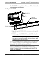
The DIN-BLOCK is designed for installation on a DIN rail. Refer to the
following diagram when installing.
Installing the DIN-BLOCK
DIN-BLOCK
DIN Rail
(Not Supplied)
DIN Rail Release
Top
1. Place the top of the DIN-BLOCK’s rail mount over the top of the
DIN rail.
2. Tilt the bottom of the DIN-BLOCK toward the DIN rail until it
snaps into place.
NOTE: When mounting DIN rail products, it may be necessary to
use a flat-head screwdriver to pull the DIN rail release tab while
snapping the device onto the DIN rail.
To remove the DIN-BLOCK from the DIN rail, use a small, flat object
(i.e., a flat-head screwdriver) to pull the DIN rail release and tilt the
bottom of the DIN-BLOCK away from the DIN rail.
NOTE: Certain third party DIN cabinets provide space for an
informational label between each DIN rail row. Crestron’s Engraver
software (version 4.0 or later) can generate appropriate labels for all
Crestron DIN rail products.

DIN Rail Cresnet
®
Distribution Block Crestron DIN-BLOCK
10
•
DIN Rail Cresnet
®
Block: DIN-BLOCK Operations & Installation Guide – DOC. 6670B
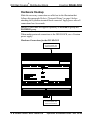
Hardware Hookup
Make the necessary connections as called out in the illustration that
follows this paragraph. Refer to “Network Wiring” on page 8 before
attaching the 4-position terminal block connector. Apply power after all
connections have been made.
NOTE: Power must be supplied separately to POWER A group and
POWER B group.
When making network connections to the DIN-BLOCK, use a Crestron
power supply.
Hardware Connections for the DIN-BLOCK
NET:
To Control System and
Other Cresnet Devices
NET:
To Control System and
Other Cresnet Devices

Crestron DIN-BLOCK DIN Rail Cresnet
®
Distribution Block
Operations & Installation Guide – DOC. 6670B DIN Rail Cresnet
®
Block: DIN-BLOCK
•
11
Problem Solving
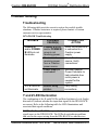
Troubleshooting
The following table provides corrective action for possible trouble
situations. If further assistance is required, please contact a Crestron
customer service representative.
DIN-BLOCK Troubleshooting
TROUBLE POSSIBLE
CAUSE(S)
CORRECTIVE
ACTION
POWER A
and/or POWER
B LEDs do not
illuminate.
POWER A group
and/or POWER B
group is not
receiving power.
Verify the DIN-BLOCK
is connected to a
Crestron power
supply.
Device is not
receiving power
from a Crestron
power source.
Use a Crestron power
source. Verify
connections.
Power supply is
overloaded.
Use the Crestron
Power Calculator to
help calculate how
much power is
needed for the
system.
Y or Z LEDs do
not illuminate.
Network wiring
problem.
Verify wiring
connections.
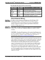
Y and Z LED Illumination
The combination of the Y and Z LEDs and their brightness levels (bright,
dim and off) indicate whether the input data signals to the DIN-BLOCK
are correct. Refer to the following table for LED illuminations and
associated data signal conditions.
NOTE: The Y and Z LEDS are provided to denote errors with the data
signal inputs to the DIN-BLOCK. The LEDs do not indicate problems
that exist in the output wiring from the DIN-BLOCK to other devices.

DIN Rail Cresnet
®
Distribution Block Crestron DIN-BLOCK
12
•
DIN Rail Cresnet
®
Block: DIN-BLOCK Operations & Installation Guide – DOC. 6670B
DIN-BLOCK Data Signal LED Troubleshooting
Y Z DATA SIGNAL CONDITIONS
Bright Dim Both Y and Z data signals present
Off Bright Both data signals missing
Bright Bright Y data signal is present, Z is missing
Off Dim Z data signal is present, Y is missing
Dim Bright Y and Z data signals reversed
Check Network Wiring
Use the
Right Wire
In order to ensure optimum performance over the full range of the
installation topology, Crestron Certified Wire and only Crestron
Certified Wire may be used. Failure to do so may incur additional
charges if support is required to identify performance deficiencies
because of using improper wire.
Calculate
Power
CAUTION: Use only Crestron power supplies for Crestron equipment.
Failure to do so could cause equipment damage or void the Crestron
warranty.
CAUTION: Provide sufficient power to the system. Insufficient power
can lead to unpredictable results or damage to the equipment. Please use
the Crestron Power Calculator to help calculate how much power is
needed for the system (www.crestron.com/calculators
).
When calculating the length of wire for a particular Cresnet run, the wire
gauge and the Cresnet power usage of each network unit to be connected
must be taken into consideration. Use Crestron Certified Wire only. If
Cresnet units are to be daisy chained on the run, the Cresnet power
usage of each network unit to be daisy chained must be added together
to determine the Cresnet power usage of the entire chain. If the unit is
home-run from a Crestron system power supply network port, the
Cresnet power usage of that unit is the Cresnet power usage of the entire
run. The wire gauge and the Cresnet power usage of the run should be
used in the following equation to calculate the cable length value on the
equation’s left side.

Crestron DIN-BLOCK DIN Rail Cresnet
®
Distribution Block
Operations & Installation Guide – DOC. 6670B DIN Rail Cresnet
®
Block: DIN-BLOCK
•
13
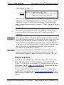
Cable Length Equation
L = Length of run (or chain) in feet
R = 6 Ohms (Crestron Certified Wire: 0.75 MM (18 AWG))
P = Cresnet power usage of entire run (or chain)
2
L <
40,000
R x P
Where:
Make sure the cable length value is less than the value calculated on the
right side of the equation. For example, a Cresnet run using 0.75 mm
2
(18 AWG) Crestron Certified Wire and drawing 20 watts should not
have a length of run more than 101 meters (333 feet). Cresnet HP cannot
be used.
NOTE: All Crestron certified Cresnet wiring must consist of two
twisted pairs. One twisted pair is the +24V conductor and the GND
conductor and the other twisted pair is the Y conductor and the Z
conductor.
Strip and
Tin Wire
When daisy chaining Cresnet units, strip the ends of the wires carefully
to avoid nicking the conductors. Twist together the ends of the wires that
share a pin on the network connector and tin the twisted connection.
Apply solder only to the ends of the twisted wires. Avoid tinning too far
up the wires or the end becomes brittle. Insert the tinned connection into
the Cresnet connector and tighten the retaining screw. Repeat the
procedure for the other three conductors.
Add Hubs
Use of a Cresnet hub/repeater (DIN-HUB) is advised whenever the
number of Cresnet devices on a network exceeds 20 or when the
combined total length of Cresnet cable exceeds 914 meters (3000 feet).
Further Inquiries
To locate specific information or resolve questions after reviewing this
guide, contact Crestron's True Blue Support at 1-888-CRESTRON
[1-888-273-7876] or refer to the listing of Crestron worldwide offices on
the Crestron Web site (www.crestron.com/offices
) for assistance within a
particular geographic region.
To post a question about Crestron products, log onto the Online Help
section of the Crestron Web site (www.crestron.com/onlinehelp
). First-
time users must establish a user account to fully benefit from all available
features.

DIN Rail Cresnet
®
Distribution Block Crestron DIN-BLOCK
14
•
DIN Rail Cresnet
®
Block: DIN-BLOCK Operations & Installation Guide – DOC. 6670B
Future Updates
As Crestron improves functions, adds new features and extends the
capabilities of the DIN-BLOCK, additional information may be made
available as manual updates. These updates are solely electronic and
serve as intermediary supplements prior to the release of a complete
technical documentation revision.
Check the Crestron Web site periodically for manual update availability
and its relevance. Updates are identified as an “Addendum” in the
Download column.

Crestron DIN-BLOCK DIN Rail Cresnet
®
Distribution Block
Operations & Installation Guide – DOC. 6670B DIN Rail Cresnet
®
Block: DIN-BLOCK
•
15
Return and Warranty Policies
Merchandise Returns / Repair Service
1. No merchandise may be returned for credit, exchange or service without prior authorization
from Crestron. To obtain warranty service for Crestron products, contact an authorized
Crestron dealer. Only authorized Crestron dealers may contact the factory and request an
RMA (Return Merchandise Authorization) number. Enclose a note specifying the nature of
the problem, name and phone number of contact person, RMA number and return address.
2. Products may be returned for credit, exchange or service with a Crestron Return Merchandise
Authorization (RMA) number. Authorized returns must be shipped freight prepaid to
Crestron, 6 Volvo Drive, Rockleigh, N.J. or its authorized subsidiaries, with RMA number
clearly marked on the outside of all cartons. Shipments arriving freight collect or without an
RMA number shall be subject to refusal. Crestron reserves the right in its sole and absolute
discretion to charge a 15% restocking fee plus shipping costs on any products returned with
an RMA.
3. Return freight charges following repair of items under warranty shall be paid by Crestron,
shipping by standard ground carrier. In the event repairs are found to be non-warranty, return
freight costs shall be paid by the purchaser.
Crestron Limited Warranty
Crestron Electronics, Inc. warrants its products to be free from manufacturing defects in materials and
workmanship under normal use for a period of three (3) years from the date of purchase from Crestron,
with the following exceptions: disk drives and any other moving or rotating mechanical parts, pan/tilt heads
and power supplies are covered for a period of one (1) year; touch screen display and overlay components
are covered for 90 days; batteries and incandescent lamps are not covered.
This warranty extends to products purchased directly from Crestron or an authorized Crestron dealer.
Purchasers should inquire of the dealer regarding the nature and extent of the dealer's warranty, if any.
Crestron shall not be liable to honor the terms of this warranty if the product has been used in any
application other than that for which it was intended or if it has been subjected to misuse, accidental
damage, modification or improper installation procedures. Furthermore, this warranty does not cover any
product that has had the serial number altered, defaced or removed.
This warranty shall be the sole and exclusive remedy to the original purchaser. In no event shall Crestron
be liable for incidental or consequential damages of any kind (property or economic damages inclusive)
arising from the sale or use of this equipment. Crestron is not liable for any claim made by a third party or
made by the purchaser for a third party.
Crestron shall, at its option, repair or replace any product found defective, without charge for parts or labor.
Repaired or replaced equipment and parts supplied under this warranty shall be covered only by the
unexpired portion of the warranty.
Except as expressly set forth in this warranty, Crestron makes no other warranties, expressed or implied,
nor authorizes any other party to offer any warranty, including any implied warranties of merchantability or
fitness for a particular purpose. Any implied warranties that may be imposed by law are limited to the terms
of this limited warranty. This warranty statement supersedes all previous warranties.

Crestron Electronics, Inc. Operations & Installation Guide – DOC. 6670B
15 Volvo Drive Rockleigh, NJ 07647 (2020752)
Tel: 888.CRESTRON 08.12
Fax: 201.767.7576 Specifications subject to
www.crestron.com change without notice.
-
 1
1
-
 2
2
-
 3
3
-
 4
4
-
 5
5
-
 6
6
-
 7
7
-
 8
8
-
 9
9
-
 10
10
-
 11
11
-
 12
12
-
 13
13
-
 14
14
-
 15
15
-
 16
16
-
 17
17
-
 18
18
-
 19
19
-
 20
20


Crestron DIN-PWS50 User guide
- Category
- Power supply units
- Type
- User guide
- This manual is also suitable for
Ask a question and I''ll find the answer in the document
Finding information in a document is now easier with AI
Related papers
-
Crestron Green Light DIN-AP2 User manual
-
-
-
-
-
-
-
-
Crestron RMC3 Operation and Installation Manual
-
Other documents
-
 Calculated Industries 6260 User manual
-
 Crestron electronic DIN-1DIMU4 User manual
-
 Crestron electronic DIN-8SW8 User manual
-
 Crestron electronic Residential Lighting User manual
-
 Crestron electronic AudioExpander User manual
-
 Crestron electronic GLS-OIR-C-450/1500 User manual
-
 Crestron electronic CLX-2DIM8 User manual
-
 Crestron electronic GLS-ODT-C-500. GLS-ODT-C-1000 User manual
-
Optimus ICALL100IP-DIN User manual
-
 Crestron electronic GLS-LCL User manual


