Page is loading ...

3M™
Drive-Thru
Systems
Quick Reference Guide
Scan wit h your mobile dev ice to access
all product training
Refer to the 3M™ Drive-Thru Systems Model G5
and XT-1 how-to videos or operating instructions for
additional information.
Instructions for G5 Headset Controls and Battery Charging .............2–3
Instructions for XT-1 Headset Controls and Battery Charging ...............4
Order Taking Modes ................................................4–5
Enter Conguration Mode (Access Base Station Settings) .................5
Greeter Setup .........................................................5
Change Basic Volume Settings ......................................... 6
Change the Monitor Volume ........................................... 6
Night Volume ......................................................... 6
Registering Headsets ...................................................7
Change Site Scheduling ................................................7
Store is Now Closed Message ...........................................8
Reboot System ........................................................8
Locating Base Station Serial Number. . . . . . . . . . . . . . . . . . . . . . . . . . . . . . . . . . . . .8
1 -800-328-0033 • 3M.com/drivethru
Reboot System
Perform the following procedure to cleanly power down, then power up without unplugging
the system:
1. Enter the conguration mode. G5: Select System Menu.
2. Select 17 Reboot System.
3. Change the value of Power Cycle Complete System to Yes.
4. G5: Press SERVICE. X T-1: Press ENTER.
Locating Base Station Serial Number
Perform the following procedure to view the revision levels and serial numbers of your base station:
1. Enter the conguration mode. G5: Select System Menu.
2. Select 18 Revision Levels.
Store is Now Closed Message
Perform the following procedure to enable or disable the automatic store closed prompt to let
customers know in your absence that the store is closed.
Note: Make sure that you disable the automatic store closed prompt in stores that are open 24 hours.
G5 only: For Dual Lane operations , this option is only available under L ane 1 display screen.
1. Enter the base station conguration mode. G5: Select System Menu.
2. Change the value for 07 Global Settings > “Store is Now Closed” Prompt? to Yes or No.
Registering Headsets (G5 or XT-1)
Each headset must be registered to a basestation before it can be used. Once registered,
it should not need to be registered again unless it is intentionally removed.
Add Headsets (G5 and/or XT-1)
Each headset has a unique identication number. The number is imprinted on the headset and
broadcast to the base station whenever it is turned on.
Note: A singl e headset should not be register ed to more than one basestation at any given site, whether or not the
bases are interconnec ted. Remove the headset from the exis ting basestation before adding it to a dierent one.
In dual-lane installations, all headsets are regis tered to Base #1. G5 shortcut: From the Main Menu, press the Left
Arrow key to quickly access the Add New Headsets registration function.
To register a headset:
1. Enter the base station conguration mode. G5: Select System Menu.
2. Select 04 Registration > 1 Add New Headsets.
3. Power on the headset when prompted. Or in the case of a G5 headset, insert the battery to
automatically power on the headset.
4. Wait up to two minutes for {Headset xxxxxxx Has Been Registered!} to appear at the bottom
of the display.
5. Repeat step 3 for additional headsets.
6. Press Mode when nished.
Remove Headsets
Perform the following steps to un-register a lost, destroyed, or otherwise removed headset from the
system, including a headset that is sent back to 3M for repair. The repaired headset would have to
be registered again at a later date.
1. Enter the base station conguration mode. G5: Select System Menu.
2. Select 04 Registration > 2 Remove Headsets.
3. Scroll to the number of the headset you want to un-register.
4. Press Enter.
Note: If you do not know or have access to the number of the headset to be unregistered, identify the headsets
that you want to remain in ser vice and un-regis ter any that remain on the list.
List All Headsets
To see a list of the registered headsets:
1. Enter the base station conguration mode. G5: Select System Menu.
2. Select 04 Registration > 3 List All Headsets.
Change Site Scheduling
The site schedule is the calendar of store open and closing times.
Note: All timekeeping is done using a 24 hour clock (e.g., 6:00 p.m. appears as 18:00).
Regular Site Schedule:
The regular site schedule is the opening and closing times for each day of the week and the times
assigned as “Day” and “Night,” which determine when the day and night volume settings change.
Perform the following procedure to set the regular site schedule:
1. Enter the base station conguration mode. G5: Select System Menu.
2. Navigate to 10 Site Scheduling > Regular Site Schedule.
3. Change the value for each day of the week and each of the four dened elds
(Open, Day, Night, and Close). Press ,, and to scroll up and down the list.
Holiday/Exception Schedule:
The holiday/exception schedule can be used to identify up to 12 days in the year on which the store
schedule is dierent than it would have been otherwise. The holiday/exception schedule should
be updated at least once a year to ensure it conforms to the current year’s calendar. Perform the
following procedure to set the holiday/exception schedule:
1. Enter the base station conguration mode. G5: Select System Menu.
2. Navigate to 10 Site Scheduling > Holiday/Exception Schedule.
3. For each day that needs a non-typical schedule, enter the three-letter month and two digit date
under Date, then change the open and close times on the line to the right of the date. Press , ,
and to scroll through the elds.
Change Basic Volume Settings
Note: All vol ume settings should be adjusted during norm al or peak busines s hours. Adjusting them during s low
times will likely produc e volume settings t hat are too low.
Note: Inbound and outbound are always dened from the perspective of the headset.
G5 only: For Dual Lane Op erations, at any ti me while conguri ng the basestation or while on the Run Screen,
you can switch the display screen to show Lane 1 or Lane 2 settings by pressi ng the Lane butto n on the keypad.
Inbound Microphone Volume
Changing the inbound microphone volume aects the sound volume coming from the customer
order point microphone. To turn up or down the inbound microphone:
1. Enter the conguration mode. G5: Select System Menu.
2. Enter a new value for 01 Drivethru Volume > Inbound Mic Volume. The range is 0 (silent) to
20 (maximum).
Outbound Talk Volume
Changing the outbound talk volume aects the volume of the speaker at the customer order point.
Note: To avoid feedback, set the outbound talk volume as low as possible.
To change the outbound talk volume:
1. Enter the conguration mode. G5: Select System Menu.
2. Enter a new value for 01 Drivethru Volume > Outbound Talk Volume. The range is
0 (silent) to 20 (maximum).
Vehicle Alert Volume
Changing the vehicle alert volume aects the volume of the vehicle alert signal on the headsets.
To change the vehicle alert volume:
1. Enter the conguration mode. G5: Select System Menu.
2. Select a new value for 01 Drivethru Volume > Vehicle Alert Volume. The range is 0 (silent) to
20 (maximum).
Outbound Greeter Message Volume
Changing the outbound greeter message volume aects the sound volume of the custom
greeting messages and the system internal greetings (“Store Closed” and “Please Pull Ahead”).
To turn up or down the greeter message volume:
1. Enter the conguration mode. G5: Select System Menu.
2. Select a new value for 01 Drivethru Volume > Greeter Message Volume. The range is
0 (silent) to 20 (maximum).
Night Volume
You can assign a standard reduction in the volume level of the customer order point speaker
for night hours when lower volume is typically required. With the night volume set, the system
automatically adjusts the volume during night hours, then back to normal during
the day. To change the night volume setting:
1. Enter the conguration mode. G5: Select System Menu.
2. Select a new value for 03 Night Volume > Reduce Drive-Thru Volume At Night By.
The range is 0 (silent) to the current day volume level (maximum).
Note: Night Volume i s never higher than Day Volume. Night volume reduction is a subtracted valu e, not
the resul ting level; therefore, if it is the same as the day volume level, the speaker will turn o at night. You
cannot change the day outb ound talk volume on this screen, only the reduction amount identied above.
Change the Monitor Volume
The monitor is an additional speaker that can be used to monitor drive-thru communication
without a headset, typically in the kitchen. If the monitor has a volume control built into it, you
can use it to control the overall volume level of the speaker. To be more specic about which
elements you want to control, follow the instructions below.
Inbound Listen
Changing the inbound listen volume aects how loudly the monitor plays the inbound (customer
order point) communication. You can also disable the monitor playing inbound sounds. To change
the inbound listen monitoring settings:
1. Enter the conguration mode. G5: Select System Menu.
2. Select 02 Monitor Volume.
3. To enable or disable the monitor playing the inbound sounds, change the value for
Inbound Listen: Enable to ON or OFF.
4. To change the volume level, select a new value for Inbound Listen: Volume. The range is
0 (silent) to 20 (maximum).
6 7
Important Safety Information
Read, understand, and follow all safety information prior to installation and operation.
Failure to follow all instructions could result in electrical shock, re and/or other
personal injury. Refer to the 3M
™
Drive-Thru Sy stems Model G 5 and XT-1 how to videos
or operating instructions for additional information.
Warranty, Limited Remedy, and Disclaimer: 3M warran ts that its wir eless commu nications pr oducts will b e free from def ects in
materi al and manufac ture for the per iod indicate d below from the d ate of shipment t o purchaser by 3 M or its authori zed dealer. 3M
MAKES NO OTHER EXPRESS OR IMPLIED WARRANTIES, INCLUDING ANY IMPLIED WARRANTY OF MERCHANTABILITY OR
FITNESS FO R A PARTICULAR P URPOSE. If th e 3M wireless c ommunicati ons product d oes not confo rm to this warra nty, the sole
and exclus ive remedy is, a t 3M’s option, re pair or repla cement of the 3M product or re fund of the purc hase price. T his warranty
does not c over: (1) the cos t of shipping pr oducts to or fr om 3M for repai r, (2) repair or repla cement of exis ting cable or w iring,
(3) produc t failure cau sed by misuse, ab use, improp er installa tion, or unapp roved modic ations, or (4) wire less communications
produc ts that are ins talled or serviced by a non- 3M authorized party. To obtain war ranty serv ice, please c ontact your au thorized
3M deale r or 3M Commer cial Soluti ons Divisio n, 3M Repair C enter, 3M FFR, 161 7 North Fron t Street, Bld g. 10, New Ulm, M innesota
56073 or c all 1-800-328 -0033.
Limitation of Liability: Except where prohibite d by law, 3M will not be li able for any los s or damage aris ing from its wi reless
communications products, whether direct, indirect, special, incidental or consequential, regardless of the legal theory asserted.
Product Warranty Period
All original G5 and XT-1 parts or components (excluding accessories,
consumable items) 24 Months
Accessories, signal enhancer, vehicle detectors 6 Months
G5 and XT-1 battery 12 Months
Consumable items (pads and windscreens) Not Warranted
3M G5 and X T-1 Drive-Thru Systems warranties include 90 days
free on-site labor from date of install (excluding defects arising
from pre-existing wiring)
3 Months
Out of warranty repair/reconditioned items/service parts 3 Months
Commercial Solutions
3M Center, Building 220-12E-04
St. Paul, MN 55144-1000
Phone 1-800-328-0033
Web 3M.com/drivethru
© 3M 2016. All rights reserved.
3M is a trademark of 3M. Used under license in Canada.
Printed in the USA. Please Recycle. 78-8134-0684-6. September 2016

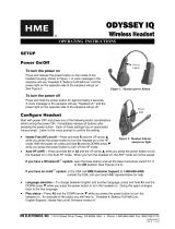
Top LED
Bottom LED
Battery Charger
Headset Charging Station
Image 1 Image 2
Volume Up
Volume Down
Tap to Release Headset
from Order Taking
Touch Zone Lane 1
Touch Zone Lane 2
ID Tag
Indicator LED (see G5 Headset
Indicator Light Modes below)
Instructions for G5 Headset Controls and Battery Charging
Headset Controls
Greeter Setup
The greeter module stores prerecorded messages and plays them back when vehicles arrive.
You can record a series of messages then select or combine them to convey standard messages
and reduce time and errors.
Enter the Greeter Conguration Menu
All of the greeter settings are located in a top-level “Greeter Setup” conguration menu.
Perform the following procedure to enter the greeter conguration menu:
1. Enter the base station conguration mode.
2. G5: Select Greeter Menu from the Main Menu. XT-1: Press and release Mode until
Greeter Setup Menu appears.
Record (Store) New Greeter, Reminder and Alert Messages
Perform the following procedure to record (store) a new greeter message using a headset:
Note: If you store a new greeter message in an occupied slot, the o ld greeter message will be permanently
erased . Each recorded me ssage can be no more than 10 seconds long for G5; 8 seconds long for X T-1.
G5 shor tcut: From the Main Menu, press the Right Arrow key to quickly access the Record Menu.
1. Put on a working headset with battery inserted and the power on.
2. At G5 basestation, enter the Greeter Menu. XT-1: Enter the greeter conguration menu.
3. Select 2 Record Messages > Record Message >XX< where “XX” represents the greeting
number you want to record (1–16).
4. Scroll to and select Rec.
5. Press and hold the Page button on the headset.
6. Press and release Service on the base station and speak the message you want to record while
continuing to hold the Page button on the headset.
7. When nished, press and release Service, then release the Page button.
8. To hear the new greeting played back, scroll to Play and press Service.
Select Message Playback Schedule
The system allows you to record and store Greeter, Alert and Reminder messages. G5: You
can store up to a maximum of 16 messages, which can be a combination of Greeter, Alert or
Reminders. XT-1: You can store up to 8 greeter messages, up to 16 reminder messages or up
to 4 alert messages. You may then select one or more of them to be played at any given time.
Perform the following procedures to schedule a message for play:
1. Enter the Greeter Menu.
2. Select 4 Message Daypart Denitions.
3. Congure start and end times for up to 12 dayparts.
4. G5 only: Select 5 Greeter Message Properties.
5. G5 only: Congure all Greeter message properties.
6. Next, select 6 Alert & Reminder Message Properties.
7. Congure each alert and reminder message
8. Select 1 Message Activation.
9. Select Msg. >XX< where “XX” represents the message number you want to schedule.
10. Select “Yes” for each active daypart.
11. Scroll to the <MON> eld, select the next day, and repeat the daypart activation for
each day of the week.
12. Set Act. to [Yes] to activate the weekly schedule for that message.
Enter Conguration Mode (Access Base Station Settings)
Conguration mode is a passcode-protected area that contains most of the conguration
options for the base station systems. With your user access, you can set up all the functionality of
the G5 Basestation (G5) and the Model XT-1 Basestation (XT-1). To enter the Conguration mode:
1. Enter your user passcode.
2. Press and release Mode key.
3. The display will show the user name and ID number (e.g., User1 ID = 1)
Order Taking Modes (continued)
Change Order Taking Mode
There are seven order taking modes, which oer dierent combinations of speaking, listening,
automatic standby, vehicle detector, and order point modes. Per form the following procedure to
switch to a dierent order taker mode:
1. Press until the Mode selection is highlighted.
2. Press Enter.
3. Press ,, or to select a new order taker mode. Your choices are
ML /P TT, M L/MLT, A L/PT T,
AL/MLT, Hands Free, Outside, and Always On. See “Order Taking Modes” on previous page.
Note: Your syste m may be congured wi th fewer order taki ng mode options than the number de scribed in this
section. You must enter User conguratio n (passcode req uired) to enable or disable individual order taking modes.
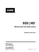
Instructions for G5 Headset Controls and Battery Charging (continued) Instructions for XT-1 Headset
Controls and Battery Charging
Headset Controls
Removing Batteries
• Slide and hold the battery release.
• Remove the discharged battery from the battery housing.
•
Insert a fully charged battery in the housing with the notch facing the
battery release. Make sure the battery is fully inserted (battery release clicks).
Charging Batteries
To charge a battery, insert battery in one of the charging slots as shown.
• The indicator lights RED to indicate the battery is charging.
• The indicator lights GREEN to indicate the battery is charged.
• Charge batteries after every shift.
Headset Cleaning
• For good health and hygiene, every headset should be cleaned on a
regular schedule.
• Before cleaning, remove the battery and the soft foam ear pad from
the headset and microphone windscreen — if used.
• Use a damp soft cloth to wipe the surfaces clean. We recommend
using a 3M™ 5040/7065 Cleaning Wipe or a Scotch-Brite® High
Performance Cloth.
• DO NOT soak the headset or immerse it in water; you might damage
the electronics.
• DO NOT bend the microphone boom.
Headset Cleaning
• For good health and hygiene, every headset should be cleaned on a regular schedule.
• Before cleaning, remove the battery and the soft foam ear pad from the headset.
• Use a damp soft cloth to wipe the surfaces clean. We recommend using a
3M™ 5040/7065 Cleaning Wipe or a Scotch-Brite® High Performance Cloth.
• DO NOT soak the headset or immerse it in water; you might damage the electronics.
• DO NOT bend the microphone boom.
Charging Batteries
To charge a battery, insert the
battery in one of the Charging
Stations or place the G5 headset
(with the battery inserted) into the
Headset Charger slot as shown.
• The LED(s) on the battery will now
ash Green indicating the battery
is currently being charged.
• All four LEDs will be lit Green
(steady) to indicate the battery is
fully charged.
• Charge batteries after every shift.
G5 Battery Indicator Light Modes
Indicator (LEDs from Top) Mode
Description
Batter y is out of G5 battery
charger and the button has
been pressed and
held down.
Each LED represents
25% charge.
All 4 LEDs Lit Green (Steady) 100% charge
3 LEDs Lit Green (Steady) 75% charge
2 LEDs Lit Green (Steady) 50% charge
1 LED Lit Green (Steady) 25% charge
Batter y is in charger and
is currently charging.
Each LED represents
25% charge.
1st LED Flashing Green up to 25% charge
2nd LED Flashing Green up to 50% charge
3rd LED Flashing Green up to 75% charge
4th LED Flashing Green up to 100% charge
Batter y end of life. Top and Bottom LEDs Lit Green Replace the
battery
G5 Headset Indicator Light Modes
Indicator Mode Description
Green (Steady) Light Lane 1 no car present, stand by
Red/Green (Steady) Light Lane 2 (Dual Lane) no car present,
stand by
Blue (Flashing) Light Vehicle arrived, but not answered
Blue (Steady) Light Vehicle present and answered
Red (Steady) Light Talk (either lane or page)
Battery Latch
Adjustment
Slide
Order
Taking Mode Listen Talk Vehicle
Detector
Automatic
Standby
Order
Point
ML/PTT Manual Push to Talk Presence On Used
ML/MLT Manual Manual
Latching Presence On Used
AL/PTT Automatic Push to Talk Presence On Used
AL/MTT Automatic Manual
Latching Presence On Used
Hands Free Automatic Automatic Presence On Used
Outside Manual Manual
Latching Ignored O Not Used
Always On Always On Manual
Latching Ignored O Used
Order Taking Modes
See your Manager to conrm which Order Taking Mode your headset is using.
Order Taking
Mode Mode Description
Manual Listen
(ML)
• Headset beeps when vehicle is detected
• Tap Talk button to turn on Customer Order Point microphone and hear the customer
• Customer Order Point microphone stays on until vehicle departs
Push To Talk
(PTT)
• Push and Hold the Talk button to talk to the customer
• Release the Talk button to turn o microphone so customer cannot hear you (Mute)
Automatic
Listen (AL)
• H eadset beeps when vehicle detected; no buttons to push — automatically hear the customer
• Customer Order Point microphone automatically turns on and stays on until vehicle depar ts
Manual
Latching Talk
(M LT)
• Tap the Talk button to talk to the customer
• Customer Order Point and Headset microphones stay on until you tap the Talk button
again or vehicle departs
Remove Replace
Indicator LED
• Green – Headset in Lane 1 Listen
• Amber – Headset in Lane 2 Listen
Volume Up
Page Button – Tap to Change Order Taker Volume Down
Talk Button Lane 2
Talk Button Lane 1
Battery
Battery Charger
Charging Status
Indicator
2 43 5
Removing Batteries
• Use your nger to gently press
up on the battery latch.
This will release the battery as
shown in Image 1.
• Using your ngernail, gently pull
the discharged battery
from the battery housing as
shown in Image 2.
• Insert a fully charged battery in
the housing with the notch on the
battery facing upward. Ensure
the battery is fully inserted.
Adjustment
Slide
/