Page is loading ...

CAIR
®
pool – DDC Controller
OPERATION MANUAL FOR SERVICE

Table of Contents CAIRpool – DDC Controller
2FläktGroup DC-2015-0116-GB 2020-01/R1 • Subject to modifications
1 Overview of Units and Packaged Content ................................. 3
1.1 Packaged content ..................................................................................... 3
1.2 Unit function .............................................................................................. 3
1.3 Accessories and special equipment ......................................................... 4
2 Safety ............................................................................................ 5
2.1 Availability of the operation manual .......................................................... 5
2.2 Scope of the operation manual ................................................................. 5
2.3 Symbols used .......................................................................................... 6
2.4 Identification of safety information ............................................................ 6
2.5 Safety-conscious work procedures .......................................................... 8
2.6 Proper use ................................................................................................ 8
2.7 Modifications and changes ....................................................................... 9
2.8 Spare parts ............................................................................................... 9
2.9 Disposal .................................................................................................... 9
2.10 Selection and qualification of personnel ................................................... 9
3 Technical Description................................................................ 10
3.1 Hardware ................................................................................................ 10
4 Assembly and Installation......................................................... 12
4.1 FläktGroup CAIRpool Control – mounted on the unit ............................. 12
4.2 FläktGroup CAIRpool Control – for separate mounting .......................... 12
4.3 On-site prerequisites............................................................................... 12
4.4 Options for switch cabinet of CAIRpool ................................................. 12
4.5 FläktGroup CAIRpool disassembly ......................................................... 13
5 Electrical Connection ................................................................ 14
5.1 Requirements.......................................................................................... 14
5.2 Connect FläktGroup CAIRpool control system ...................................... 15
6 Operation .................................................................................... 17
6.1 Activation codes ..................................................................................... 17
6.2 Login/authorization levels ....................................................................... 18
6.3 Basic operation ...................................................................................... 18
6.4 START Group ......................................................................................... 19
6.5 Plant group.............................................................................................. 21
6.6 Group Plant Activation ........................................................................... 22
6.7 Setpoint group ........................................................................................ 25
6.8 Messages group ..................................................................................... 25
6.9 Group messages .................................................................................... 26
6.10 TRENDS Group ..................................................................................... 29
6.11 Networking group ................................................................................... 35
6.12 Group settings ........................................................................................ 36
6.13 SYSTEM Group ..................................................................................... 48
6.14 INFO Group ........................................................................................... 57
7 Error Messages .......................................................................... 58
8 Visualization with an Internet Browser .................................... 65
8.1 Mobile terminals (tablet, Smartphone) .................................................... 65

CAIRpool – DDC Controller Overview of Units and Packaged Content
FläktGroup DC-2015-0104-GB 2020-01/R1 • Subject to modifications3
1 Overview of Units and Packaged Content
Each air-handling unit carries a unit code plate somewhere inside the equipment,
which contains:
– Unit or serial number
– Contact data
•Any discrepancies should be immediately reported to FläktGroup.
•Fill in the provided fields.
1.1 Packaged content
The following components are included in the scope of delivery:
– Units of CAIRpool 015 to 360 series with an inbuilt microprocessor control and touch
screen display
–Unit documentation includes
– Current operation manual with all relevant data on supplied unit
– Controller manual for operating microprocessor controller
– Wiring diagram
– Dimensional drawing
– Spare part list
– CE declaration of conformity
– Possible accessories and special equipment (only if ordered)
1.2 Unit function
CAIRpool units are designed as dehumidifier units for swimming pools.
The different unit models are based on the strategy of dehumidification with outdoor
air. Depending on the swimming pool humidity, different quantities of fresh air are sup-
plied to the swimming pool for dehumidification.
P_X Design The basic model of CAIRpool dehumidifiers for swimming pools comprises a unit
series with highly efficient heat recovery of the P_X series.
P_I Design The units with an inverter-controlled heat pump P_I are based on this model. The heat
pump enables an additional stage of heat recovery for the swimming pool.
Units with a heat pump can contain a pool or fresh-water condenser as an option. In
this case, a part of the heat pump capacity can be released directly to the pool water
or to a water treatment plant (please consider water quality)
P_R Design The P_R series is available to the user as premium solution. The swimming pool is
heated via the inverter-controlled heat pump and can be cooled to nominal tempera-
ture in summer or in case of high external temperatures through a changeover switch.
When the plants are equipped with a heat pump, the heat pump provides the residual
ventilation heat for heating the swimming pool. In winter or at commissioning, a down-
stream heater bank provides a sufficient supply of heat. Furthermore, the reheater coil
regulates the heat function when the heat pump is not in operation or disabled by the
controller because of insufficient quantities of outdoor air.
Units with a heat pump can contain a pool or fresh-water condenser as an option. In
this case, a part of the heat pump capacity can be released directly to the pool water
or to a water treatment plant (please consider water quality)

Overview of Units and Packaged Content CAIRpool – DDC Controller
4FläktGroup DC-2015-0104-GB 2020-01/R1 • Subject to modifications
1.3 Accessories and special equipment
To determine the scope of options fitted to your unit, compare the supplied unit 'Model
Number' with the unit model number specified on the unit code plate.
1.3.1 Filtration
– M5 or F7, or of higher quality
1.3.2 Controls options
– Modbus RTU and IP
– LON IP
– BACnet IP
1.3.3 Sensor options
– Moisture shift
– Extension for sensors via heat recovery
– Parallel circuit units
– Separate fans, fresh air ventilation at construction side/cold smoke extraction
1.3.4 Miscellaneous
– Electric heater
– Frost protection for outdoor installation
1.3.5 Casing optionsswitch cabinet
– Without

CAIRpool – DDC Controller Safety
FläktGroup DC-2015-0104-GB 2020-01/R1 • Subject to modifications5
2 Safety
The control and monitoring system CAIRpool is built according to the latest state of
technology and approved safety engineering regulations. Use the CAIRpool system
only in fully acceptable technical condition only for its intended use. Observe all rele-
vant safety instructions and precautions in the Operation Manual. Use proper safety
measures to prevent hazardous situations which, if not avoided, could result in a threat
to life and limb of the user or third parties or damage the system itself, connected units,
or other property!
Have all faults repaired by an authorized specialist without delay!
2.1 Availability of the operation manual
This operation manual contains important instructions regarding the safe and proper
operation of the control and monitoring system CAIRpool .
The operation manual is intended for use by fitting and installation companies, building
services engineers, technical personnel or trained persons as well as electrical and
refrigeration engineering specialists.
This operation manual must be available at the location of the CAIRpool at all times.
When working on the CAIRpool, observe all instructions and precautions in the current
operation manual, in particular the chapter on safety.
2.2 Scope of the operation manual
This operation manual as well as the instructions of the manufacturer of the individual
components provide you the necessary information on the areas:
– Assembly/disassembly
– Installation
– Commissioning
–Operation
– Fault Finding and Troubleshooting
– Maintenance
ATTENTION
Damage to the unit!
•In the case of alarms and faults always make sure that the cause of the fault is
investigated.
In particular, multiple resetting of fault signals without rectifying the cause can
lead to extended unit damage and invalide the warranty.
Notice!
The electric connection is on the right as standard.
See accompanying controller handbook!

Safety CAIRpool – DDC Controller
6FläktGroup DC-2015-0104-GB 2020-01/R1 • Subject to modifications
2.3 Symbols used
The following symbols are used to highlight particular text sections in this operation
manual:
– This symbol is used to indicate normal lists.
•This symbol indicates handling instructions.
This symbol indicates the result of an action.
2.4 Identification of safety information
The following symbols and notices are provided in appropriate places throughout this
document to designate the safety instructions:
2.4.1 DANGER - Death/serious irreversible injury
Indicates an extremely hazardous situation which will result in death or serious irre-
versible injury, if the safety instruction is not followed.
Example:
2.4.2 WARNING - Death/serious injury
Indicates a hazardous situation which can result in death or serious irreversible injury,
if the safety instruction is not followed.
Example:
Notice!
Additional details on using the GEA unit are specified here.
Electrocution through hazardous voltage will lead to death or serious injury!
•Power down all supply lines and ensure that they cannot be accidentally switched
on.
•Ensure that the unit is voltage-free and isolated, earth and short circuit the unit,
cover or shield off neighboring live components.
Danger due to toxic substances!
•While working with hydraulics using a naked flame, make sure to avoid contact
with inflammable surfaces.
If the electrical insulation, panel insulation, insulation of electrical cables, vinyl
coatings, paint, rubber or plastic parts is exposed to naked flame, toxic fumes will
be given off.
•Therefore, while working with a flame or a heat source, the job site must be
thoroughly ventilated.

CAIRpool – DDC Controller Safety
FläktGroup DC-2015-0104-GB 2020-01/R1 • Subject to modifications7
2.4.3 CAUTION - Minor or moderate injury
Indicates a hazardous situation which can result in minor or moderate injury if the
safety instruction is not followed.
Example:
2.4.4 ATTENTION – Environmental or material damage
Indicates actions that can result in damage to equipment or property.
Examples:
2.4.5 Safety symbols used
Sharp edges can cause injuries!
Observe precaution when cleaning due to risk of cuts on thin and sharp edges.
•Wear chemical-resistant gloves.
ATTENTION
ATTENTION
Environmental Damage!
•Do not pollute the environment with liquid products.
•Dispose such materials in accordance with local laws and regulations and avoid
harm to the environment.
Ethylene glycol and propylene glycol are in Water Hazard Class 1 (mild water pol-
lutants) in the catalog of water pollutants. This also applies to mixtures with water.
ATTENTION
Device damage from static discharge!
•While carrying out adjustment work on the CAIR System, make sure that you
discharge yourself statically before touching the circuit board and electrical
components.
Electrical hazard
Personal injury
Environmental damage
Damage to the unit
Static discharge

Safety CAIRpool – DDC Controller
8FläktGroup DC-2015-0104-GB 2020-01/R1 • Subject to modifications
2.5 Safety-conscious work procedures
Observe the following instructions when carrying out installation, adjustment or repair
jobs:
To comply with EN 378-3 you must wear suitable Personal Protective Equipment
(PPE) at all times when working on a CAIRpool unit. Only qualified staff with a history
of assessing and minimizing risk should be allowed to work on the equipment. As a
minimum we would suggest suitable safety footwear, suitable gloves, suitable eye pro-
tection and suitable overalls. More PPE. may be required depending on your personal
risk assessment.
For carrying out work near low-voltage networks:
For work on the electronic components:
For all jobs
2.6 Proper use
The CAIRpool system exclusively serves the control and regulation of specific HVAC
units from FläktGroup. The CAIRpool system is used:
– to control the extract-air /supply-air temperature
– To regulate the fan speed (volume flow/duct pressure)
– to regulate the dehumidification
– The switch cabinet with its door mounting kit has the protection class IP55
Improper use Any use other than that described above is considered improper. The manufacturer/
supplier is not liable for any damages arising from improper use. The user alone bears
the risk.
Electrocution through hazardous voltage will lead to death or serious injury!
•Power down all supply lines and ensure that they cannot be accidentally switched
on.
•Ensure that the unit is voltage-free and isolated, earth and short circuit the unit,
cover or shield off neighboring live components.
ATTENTION
Device damage from static discharge!
•While carrying out adjustment work on the CAIR System, make sure that you
discharge yourself statically before touching the circuit board and electrical
components.
ATTENTION
Device damage from static discharge!
•Observe all assembly instructions for the CAIRpool control panel.
Fluctuations and deviations in the supply voltage may not exceed the tolerance
limits specified in the technical data, otherwise functional failures and limit states
cannot be excluded.

CAIRpool – DDC Controller Safety
FläktGroup DC-2015-0104-GB 2020-01/R1 • Subject to modifications9
2.7 Modifications and changes
Changes, alterations or modifications on the CAIRpool system are not allowed.
Tampering with or modifying the CAIRpool system will invalidate the CE conformity
and void all warranty entitlements.
2.8 Spare parts
Only original FläktGroup spare parts are allowed, since FläktGroup is not liable if third-
party spare parts are used. The spare part list is enclosed with the unit documentation.
2.9 Disposal
Dispose of main and operating supply materials as well as other components accord-
ing to material type in a safe and environmentally friendly manner – always refer to your
local by-laws and country-specific legislation (also refer to the chapter on disposal in
the operating manual of the unit).
2.10 Selection and qualification of personnel
Ensure that every person commissioned to work on the CAIRpool system has com-
pletely read and understood this operation manual – especially the chapter on safety.
Please read this document fully before commencing any work, and not while perform-
ing a task.
Electrical connections may only be carried out by qualified licensed staff or other indi-
viduals with proper professional training and experience in the following areas:
– Regulations concerning health and safety in the workplace
– Accident prevention regulations
– Directives and recognized codes of practice
All jobs with the refrigeration circuit shall be performed only by certified and licensed
staff in accordance with the valid EG Regulation 842/2006 Article 5, EG Regulation
303/2008 Article 4 and 5 as well as "Ordinance on climate protection against changes
caused by release of certain fluorinated greenhouse gases".
All skilled staff must be able to assess the entrusted work and must be able to recog-
nize and avoid all associated dangers.
DAMAGE TO UNIT AND PERSONAL INJURY
The CAIRpool system may not be operated:
– in areas subject to explosion risk
– in rooms with conductive dust
– in rooms with strong electromagnetic fields
– in rooms with aggressive atmosphere that attacks plastics, for instance.
– in wet areas
– in areas with high dust content

Technical Description CAIRpool – DDC Controller
10 FläktGroup DC-2015-0104-GB 2020-01/R1 • Subject to modifications
3 Technical Description
3.1 Hardware
The FläktGroup CAIRpool control system is integrated in the switch cabinet.
It consists of a control unit PCD3.M90 and additional fixtures such as motor circuit
breaker, fuses, and coupler relays.
A touch display is located in the switch cabinet front panel for operation.
Fig. 3-1: Switch cabinet with display
3.1.1 Structure of the switch cabinet
Fig. 3-2: Structure of the switch cabinet
Touch Display
Main switch
Control/regulation
Contactors
Motor circuit breaker,
fuses
Terminal block
Coupler relays
Power supply, transformer
Main switch

CAIRpool – DDC Controller Technical Description
FläktGroup DC-2015-0104-GB 2020-01/R1 • Subject to modifications11
3.1.2 Assembling of the CAIRpool control and steering system
The control system consists of a main module PCD3.M90.
Fig. 3-3: Main module PCD3.M90

Assembly and Installation CAIRpool – DDC Controller
12 FläktGroup DC-2015-0104-GB 2020-01/R1 • Subject to modifications
4 Assembly and Installation
4.1 FläktGroup CAIRpool Control – mounted on the unit
Depending on the model ordered, the FläktGroup CAIRpool control is delivered
mounted on the unit. The electrical connections within the unit sub-divisions as well as
the power supply and possible optional connections must be created.
4.2 FläktGroup CAIRpool Control – for separate mounting
Depending on the model ordered, the FläktGroup CAIRpool control is delivered as a
separate component. The electrical connections from the control (switch cabinet) to the
unit as well as the power supply and possible optional connections must be created.
4.3 On-site prerequisites
The FläktGroup CAIRpool control may not be mounted and operated:
– in areas subject to explosion risk
– in rooms with conductive dusts or dusty air
– in rooms with strong electromagnetic fields
– in rooms with an aggressive atmosphere that attacks plastics, for instance
– in damp rooms and wet areas
– outdoors (assembly in outdoor areas)
•If possible, assemble the FläktGroup CAIRpool control in the vicinity of the central
air-handling unit. You can reduce the cabling lengths and avoid possible
interference by external influences.
4.4 Options for switch cabinet of CAIRpool
The FläktGroup CAIRpool control is suitable for the vertical assembly on a solid sur-
face such as a wall.
•Select suitable fasteners (screws, dowels) according to the unit weight and the
characteristics of the substrate.
•Secure the CAIRpool sheet steel cabinet to all provided suspension openings on the
substrate with the fasteners.
Assemble the cabinet on the corner of the supply-air units with the delivered retaining
parts – see the assembly instructions of the unit.
NOTICE ON THE ASSEMBLY OF THE UNIT
Here you will find information on how to assemble and install the unit.
Assembly must only be carried out by qualified specialists with proper professional
training and experience in the relevant accident prevention regulations as well as
other generally recognized safety and occupational health codes.
Electrocution through hazardous voltage will lead to death or serious injury!
The electrical installation and (dis)assembly of the CAIRpool control may only be car-
ried out by qualified electricians trained for this purpose in compliance with this oper-
ation manual and the valid VDE regulations.
•Before drilling, ensure that the drilling area is free from electrical cables and pipes.
•Only indoor mounting of the CAIRpool control is allowed.

CAIRpool – DDC Controller Assembly and Installation
FläktGroup DC-2015-0104-GB 2020-01/R1 • Subject to modifications13
4.5 FläktGroup CAIRpool disassembly
Electrocution through hazardous voltage will lead to death or serious injury!
If it becomes necessary to disassemble the CAIRpool control system, it is mandatory
to perform the following operations:
•Switch off the unit
•Switch off the master switch of the supply line, disconnect the unit from mains
power, secure against subsequent switch-on, confirm zero-voltage, ground and
short-circuit and cover or isolate adjacent electrically-charged parts. Non-
compliance can lead to death or serious injury.
•Deactivate external power sources. These external power sources can originate
e.g. from external enabling, etc.

Electrical Connection CAIRpool – DDC Controller
14 FläktGroup DC-2015-0104-GB 2020-01/R1 • Subject to modifications
5 Electrical Connection
Ensure and observe protective measures!
When installing and connecting the unit, observe all protective measures for low-volt-
age systems according to the EU Directive as well as regulations and codes of the local
utility provider. Potential equalization must be provided and equipment with all con-
nected components must be earthed.
5.1 Requirements
•Before you start setting up the unit's electrical connections, check the following:
– Air handling unit must be mounted
– Switch cabinet must be mounted
5.1.1 Type of cables used
Motor and control cable •For the main current and control cables (e.g. motor cable, actuators, external
messages, etc.) depending on the type of wiring, electrical capacity and line lengths
that comply with current standards and regulations.
Shielded cable •Definitely use screened cable (copper weave shielding) for low-voltage signals of
sensor systems and actuators. Especially check the MODbus data cable. This way
possible interferences and faults can be prevented.
NOTICE!
Electrical connections must only be carried out by qualified licensed staff or other
individuals with proper professional training and experience in the relevant acci-
dent prevention regulations, as well as other generally recognized safety and occu-
pational health codes.
Electrocution through hazardous voltage will lead to death or serious injury!
•Power down all supply lines and ensure that they cannot be accidentally switched
on.
•Ensure that the unit is voltage-free and isolated, earth and short circuit the unit,
cover or shield off neighboring live components.

CAIRpool – DDC Controller Electrical Connection
FläktGroup DC-2015-0104-GB 2020-01/R1 • Subject to modifications15
5.2 Connect FläktGroup CAIRpool control system
5.2.1 Preparing cable entry points
There are sufficient stampings for the cable glands on the mounting plate.
•Punch through the required number of pre-stamped cable glands.
•Install the connectors of the cable glands in such a way to ensure the protection
class and cable tension relief.
•Route only the permissible number of cables for each cable gland (standard screw
= 1 cable).
•Use the correct screw size according to the cable diameter to ensure the required
leak tightness of the cable screw.
5.2.2 Overview of the terminal block
The electrical connections to be individually performed before switching on the CAIR-
pool control are listed in the wiring diagram. Available optional connections are those
present that exceed the basic function of the unit are marked as "optional", depending
on the delivered unit version.
Pos. 1: 230/400 V motor and pump outputs
Pos. 2:PE track
Pos. 3: Main switch / connection for power supply
Pos. 4: Control inputs/control outputs
Pos. 5: Terminal strip shielding
Pos. 6: Connecting terminal for control inputs/
control outputs with low voltage and sen-
sor systems
Pos. 7: Control panel connection
Notice!
Cable gland screws are not components of the packaged content of the compact
controls.
1 2 3 4 5 6 7

Electrical Connection CAIRpool – DDC Controller
16 FläktGroup DC-2015-0104-GB 2020-01/R1 • Subject to modifications
5.2.3 Connect cable shield
For the shielded low voltage lines (sensor systems, actuator, etc.), a sufficient number
of shielded fastening possibilities is provided.
•Insulate the cable at the location to be contacted.
•Secure the bare screen on the rail using two cable straps.
•Make sure that the cable screen is firmly placed on the earth contact rail with the
largest possible surface contact.
5.2.4 Make electrical connection
The FläktGroup CAIRpool Control is designed with spring-type terminals as single and
double terminal blocks. Row terminal strips with spring-cage connection can be
clamped with or without wire-end sleeves.
•Use an appropriate screwdriver (size and form) to connect lines.
•Make the electrical connection of the FläktGroup CAIRpool Control according to the
enclosed wiring and terminal diagram.

CAIRpool – DDC Controller Operation
FläktGroup DC-2015-0104-GB 2020-01/R1 • Subject to modifications17
6Operation
All CAIRpool plants are routinely equipped with a full-graphics, multilingual visual dis-
play system. This visualization is provided with the WEB server integrated in the con-
trol.
The visualization provides the following access options:
– Directly at the plant itself via TFT display in the cabinet door;
–With a PC via internet browser
access possible directly at the plant as well as via on-site intranet or internet The
necessary installation of a Java plug-in for the browser used is described in chapter
„Visualization with an Internet Browser“ on page 65.
–With a smartphone
that requires a commercially available app that provides both the iOS as well as the
Android operating systems from Google
The visualization allows the following activities:
– Configuration and parameterization of the plant
– Observation and operation of the plant
– Setpoint values
– Viewing the archived measured values
– Display of fault, event, and maintenance messages
– Display of the plant documentation
– Export of the measuring and messages archive for external examination e. g. in
Excel
– Backing up and loading the plant parameters
– Monitoring and pre-setting the inputs and outputs.
The complete visualization is subdivided into main groups:
–Start
– Plant (schematic units/sensor systems)
– Activate plant
– Entries (setpoints)
– Displays
– Messages
–Trends
– Networking (BMS/network)
– Control settings
– System settings
–Info
6.1 Activation codes
6.1.1 Program blockage
The units are delivered in the blocked state.
When initially switched on, the plant startup screen displays the
following information: Until the activation code is entered, only
these pages are accessible:
– View the contact data of the plant supplier
(see „Contact“ on page 20)
– Change the language of the user interface
(see „Language“ on page 20)

Operation CAIRpool – DDC Controller
18 FläktGroup DC-2015-0104-GB 2020-01/R1 • Subject to modifications
6.2 Login/authorization levels
Use the startup screen to log into the system.
There are the following authorization levels:
Guest – Access to almost all monitors (without change rights)
– No password is required
Operator – Change rights of relevant setpoints
– Manual operation of the drives
– Switch unit ON and OFF
– Acknowledge faults
– Export archive
– Default password: "1234"
Service – Additionally entitled to change the service settings
– Default password 9992
Factory login – No limitations
•Enter login password (operator) in the textbox and confirm
by pressing OK (PC: Return key) .
•After successful login, press to switch over to the PLANT
operator screen.
With logout or after 15 minutes inactivity, access is reset to
GUEST.
•Press without entering a password.
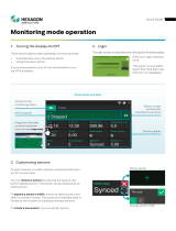
6.3 Basic operation
The fundamental sceen design is explained on the basis of a
monitor screen from the PLANT group.
Top line: Headline, current time and current date, as well as plant signal lights with the following
assignment:
– LED left: display Plant ON (green)
– LED middle:plant malfunction (red)
– LED right:service request (yellow)
The display of "F" here signals an activated pre-set (forced) operation!
Second line (optional): Navigation within a group. The selected image is marked in color here.
Primary area: Operation and observation of the functional characteristics in accordance with the
selected subsection
Bottom line: Navigation in the main groups with buttons and pictographs. The current group is high-
lighted with a yellow border on the button.

CAIRpool – DDC Controller Operation
FläktGroup DC-2015-0104-GB 2020-01/R1 • Subject to modifications19
6.4 START Group
6.4.1 Startup screen
After the plant is switched on, the startup screen appears.
•You can log into the startup screen by entering the pass-
word.
You must confirm the entry by pressing OK (PC: Return key)
to display the access rights in the startup screen.
After completed login and 15 minutes inactivity, the system
automatically logs out and the display reverts back to the
startup screen.
•You can also activate the unit in the startup screen if it has a
program block – see "Program blockage" on page 17.
•The following special functions can be accessed in the startup screen with the
buttons:
System User Interface– see „System User Interface“ on page 19
Contact – see „Contact“ on page 20
Language Selection – see „Language“ on page 20
6.4.2 System User Interface •Press the System User Interface button
The screen System User Interface appears.
All important functions and values are consolidated on the Sys-
tem User Interface screen.

Operation CAIRpool – DDC Controller
20 FläktGroup DC-2015-0104-GB 2020-01/R1 • Subject to modifications
6.4.3 Contact
•Press the Contact button.
The CONTACT screen appears.
•At need, you can access the data at all times in the Contact
screen.
6.4.4 Language
•Press the Language button.
•In the Language screen you can select the desired lan-
guage by tapping the appropriate national flag.
6.4.5 Info • Press the Info button.
The INFO screen appears
It shows an overview of the symbols and pictograms used in
the system, along with a short description.
The system itself can be operated intuitively.
NOTICE!
•During commissioning, fill in the Contact screen
with all important contact data!
Filling out the contact form is possible with "Ser-
vice" access rights.
/