Page is loading ...

Pololu A-Star 32U4 Robot
Controller User’s Guide
Pololu A-Star 32U4 Robot Controller User’s Guide © 2001–2019 Pololu Corporation
https://www.pololu.com/docs/0J66/all Page 1 of 50

1. Overview . . . . . . . . . . . . . . . . . . . . . . . . . . . . . . . . . . . . . . . . . . . . . . 3
1.1. Supported operating systems . . . . . . . . . . . . . . . . . . . . . . . . . . . . . . . . 6
2. Contacting Pololu . . . . . . . . . . . . . . . . . . . . . . . . . . . . . . . . . . . . . . . . . . 7
3. A-Star 32U4 Robot Controller with Raspberry Pi Bridge . . . . . . . . . . . . . . . . . . . . . . 8
3.1. Microcontroller . . . . . . . . . . . . . . . . . . . . . . . . . . . . . . . . . . . . . . . . 8
3.2. User interface . . . . . . . . . . . . . . . . . . . . . . . . . . . . . . . . . . . . . . . . 8
3.3. LV motor drivers . . . . . . . . . . . . . . . . . . . . . . . . . . . . . . . . . . . . . . 10
3.4. SV motor drivers . . . . . . . . . . . . . . . . . . . . . . . . . . . . . . . . . . . . . . 12
3.5. Power . . . . . . . . . . . . . . . . . . . . . . . . . . . . . . . . . . . . . . . . . . . 14
3.6. LV regulator . . . . . . . . . . . . . . . . . . . . . . . . . . . . . . . . . . . . . . . . 16
3.7. SV regulator . . . . . . . . . . . . . . . . . . . . . . . . . . . . . . . . . . . . . . . . 18
3.8. Raspberry Pi interface and level shifters . . . . . . . . . . . . . . . . . . . . . . . . . 19
3.9. Pinout . . . . . . . . . . . . . . . . . . . . . . . . . . . . . . . . . . . . . . . . . . . 22
3.10. Pin assignments . . . . . . . . . . . . . . . . . . . . . . . . . . . . . . . . . . . . . 25
3.11. AVR Timers . . . . . . . . . . . . . . . . . . . . . . . . . . . . . . . . . . . . . . . . 28
3.12. Schematics and dimensions . . . . . . . . . . . . . . . . . . . . . . . . . . . . . . . 28
4. Getting started . . . . . . . . . . . . . . . . . . . . . . . . . . . . . . . . . . . . . . . . . . 30
4.1. Installing Windows drivers . . . . . . . . . . . . . . . . . . . . . . . . . . . . . . . . . 30
4.2. Programming using the Arduino IDE . . . . . . . . . . . . . . . . . . . . . . . . . . . 32
4.3. Programming using avr-gcc and AVRDUDE . . . . . . . . . . . . . . . . . . . . . . . 37
5. A-Star 32U4 Arduino library . . . . . . . . . . . . . . . . . . . . . . . . . . . . . . . . . . . 40
6. The A-Star 32U4 USB interface . . . . . . . . . . . . . . . . . . . . . . . . . . . . . . . . . 41
7. The A-Star 32U4 Bootloader . . . . . . . . . . . . . . . . . . . . . . . . . . . . . . . . . . . 43
8. Reviving an unresponsive A-Star . . . . . . . . . . . . . . . . . . . . . . . . . . . . . . . . 46
8.1. Reviving using the Arduino IDE . . . . . . . . . . . . . . . . . . . . . . . . . . . . . . 46
8.2. Reviving using AVRDUDE . . . . . . . . . . . . . . . . . . . . . . . . . . . . . . . . . 48
9. Related resources . . . . . . . . . . . . . . . . . . . . . . . . . . . . . . . . . . . . . . . . 50
Pololu A-Star 32U4 Robot Controller User’s Guide © 2001–2019 Pololu Corporation
Page 2 of 50

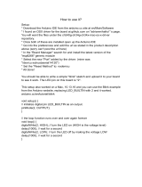
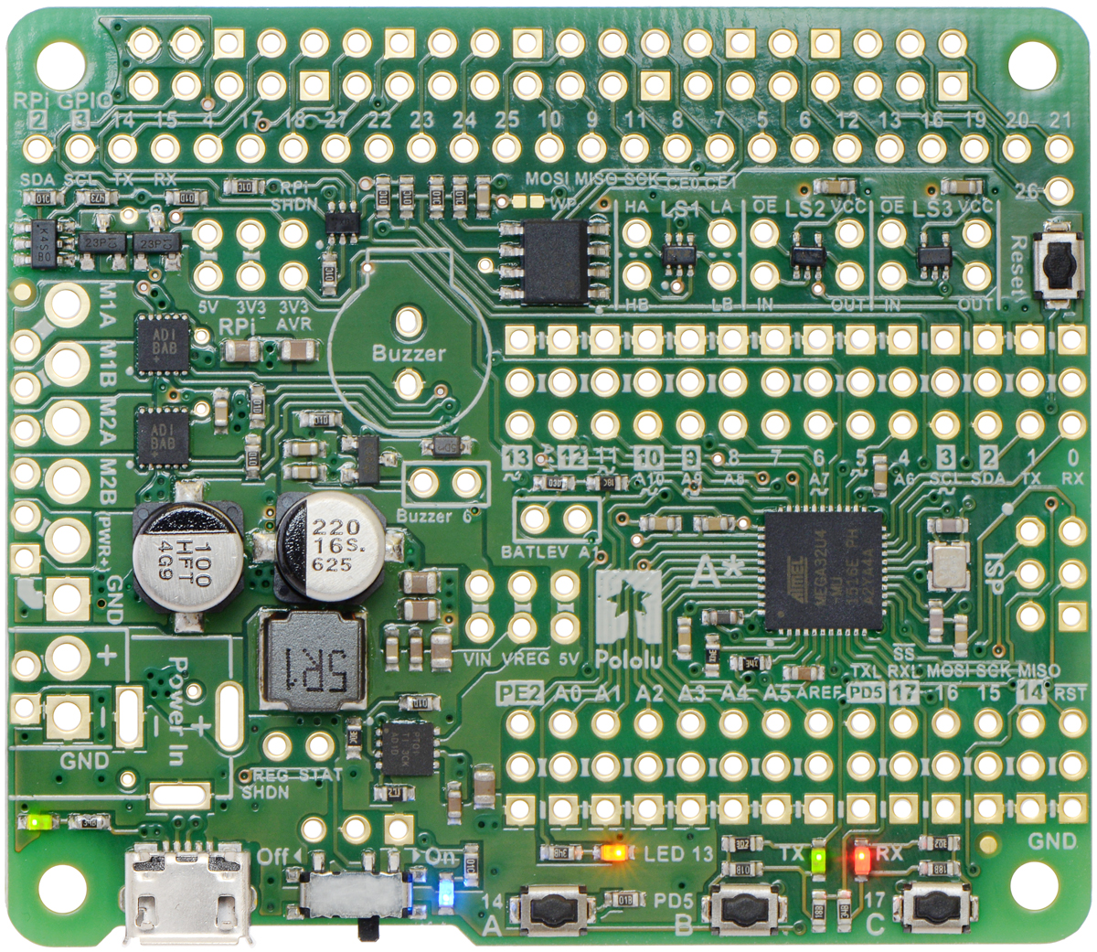
A-Star 32U4 Robot Controller LV with Raspberry
Pi Bridge (SMT components only).
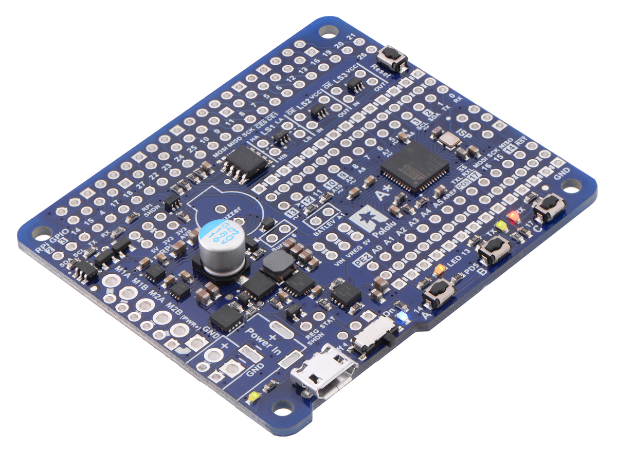
A-Star 32U4 Robot Controller SV with Raspberry
Pi Bridge (SMT components only).
1. Overview
The Pololu A-Star 32U4 Robot Controller with
Raspberry Pi Bridge is a programmable module
designed to be the core of a small robot, either
as an auxiliary controller atop a Raspberry Pi
base or as a complete control solution on its
own.
At its heart is an Atmel ATmega32U4 AVR
microcontroller, which has 32 KB of flash
program memory, 2.5 KB of RAM, and built-in
USB functionality. The controller adds a
complement of peripheral hardware useful for
robotics applications, including dual H-bridge
motor drivers capable of delivering at least 1.7 A
per channel continuously, as well as an efficient
switching voltage regulator and level shifters that
enable it to power and communicate with a
Raspberry Pi.
This A-Star is available in two versions with
different operating voltage ranges: the Robot
Controller LV (blue solder mask) accepts a 2.7 V
to 11 V input voltage, and the Robot Controller
SV (green solder mask) accepts a 5.5 V to 36 V
input voltage.
Like other A-Star programmable controllers
[https://www.pololu.com/category/149/a-star-
programmable-controllers] (abbreviated A*), the
robot controller features a USB interface and ships with a preloaded Arduino-compatible bootloader.
We provide a software add-on that enables it to be easily programmed from the Arduino environment,
as well as an Arduino library to help interface with its on-board hardware.
A USB A to Micro-B cable [https://www.pololu.com/product/2072] (not included) is required
to connect the A-Star 32U4 Robot Controller to a computer.
Pololu A-Star 32U4 Robot Controller User’s Guide © 2001–2019 Pololu Corporation
1. Overview Page 3 of 50

Features
• Dimensions: 65 mm × 56 mm (2.6″ × 2.2″)
• Programmable ATmega32U4 MCU with 32 KB flash, 2.5 KB SRAM, 1 KB EEPROM, and
native full-speed USB (clocked by precision 16 MHz crystal oscillator)
• Preloaded with Arduino-compatible bootloader (no external programmer required)
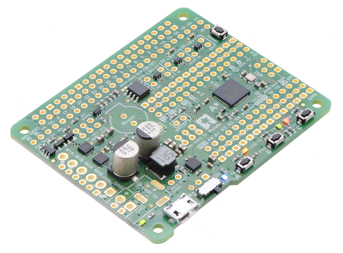
• All 26 general-purpose I/O lines from the ATmega32U4 are broken out (including PB0, PD5,
and PE2); 7 of these can be used as hardware PWM outputs and 12 of these can be used as
analog inputs (some I/O lines are used by on-board hardware)
• Convenient 0.1″-spaced power, ground, and signal connection points
• Dual bidirectional motor drivers (≥1.7 A per channel)
• Buzzer option for simple sounds and music
• 3 user-controllable LEDs
• 3 user pushbuttons
• Reset button
• Level shifters for interfacing 5 V logic to 3.3 V Raspberry Pi
• Power features:
◦ 5 V power can be sourced from USB or from external supply through on-board
regulator (with several access points for connecting external power)
▪ LV: 2.7 V to 11 V input
▪ SV: 5.5 V to 36 V input
◦ Switching 5 V regulator enables efficient operation
◦ Power switch for external power inputs
◦ Reverse-voltage protection on external power inputs
◦ Power selection circuit allows for seamless switching between power sources while
providing overcurrent protection, and feedback about which power source is
selected
◦ Provides 5 V power to Raspberry Pi
• 6-pin ISP header for use with an external programmer [https://www.pololu.com/product/3172]
Pololu A-Star 32U4 Robot Controller User’s Guide © 2001–2019 Pololu Corporation
1. Overview Page 4 of 50

A-Star comparison table
A-Star 328PB
Micro
A-Star 32U4
Micro
A-Star 32U4 Mini
ULV
A-Star 32U4 Mini
LV
A-Star 32U4 Mini
SV
A-Star 32U4
Prime LV
A-Star 32U4
Prime SV
A-Star 32U4 Robot
Controller LV
A-Star 32U4 Robot
Controller SV
Microcontroller: ATmega328PB ATmega32U4
User I/O lines: 24 18 26
26
(1)
26
(1)
PWM outputs: 9 7 7 7
7
(1)
Analog inputs: 8 8 12 12
12
(1)
Ground access
points:
6 2 4 43 44
User LEDs: 1 2 3 3 3
User
pushbuttons:
— — — 3 3
USB interface:
Reset button:
Power switch:
Buzzer option:
microSD option:
LCD option:
Motor drivers:
Operating
voltage:
3.3V VCC: 3.8 V to
15 V
5V VCC: 5.5 V to
15 V
5.5 V to 15 V
ULV: 0.5 V to
5.5 V
LV: 2.7 V to 11.8 V
SV: 5 V to 40 V
LV: 2 V to 16 V
SV: 5 V to 36 V
LV: 2.7 V to 11 V
SV: 5.5 V to 36 V
Regulator type: 3.3 V or 5 V linear 5 V linear
5 V switching
ULV: step-up
LV: step-up/step-
down
SV: step-down
5 V switching
LV: step-up/step-
down
SV: step-down
5 V switching
LV: step-up/step-down
SV: step-down
Regulated
current:
(2)
100 mA 100 mA
ULV: 500 mA
LV: 1 A
SV: 800 mA
LV: 1.8 A
SV: 1 A
LV: 1 A
SV: 1.5 A
Dimensions: 1.3″ × 0.7″ 1″ × 0.6″ 1.9″ × 0.7″ 2.8″ × 2.1″ 2.6″ × 2.2″
Weight:
1.5 g
(3)
1.3 g
(3)
3.4 g
(3)
13 g to 33 g 14 g to 23 g
1 Some microcontroller resources are used by on-board hardware.
2 These values are rough approximations for comparison purposes. Available current depends on input voltage, current consumed
by the board, ambient conditions, and regulator topology. See product documentation and performance graphs for details.
3 Without included optional headers.
Pololu A-Star 32U4 Robot Controller User’s Guide © 2001–2019 Pololu Corporation
1. Overview Page 5 of 50

1.1. Supported operating systems
The A-Star 32U4 Robot Controller can be programmed using any operating system that supports the
Arduino environment. We have tested the A-Stars, our Arduino software add-on, and the Arduino IDE
on Microsoft Windows 10, 8.1, 8, 7, Vista, XP (with Service Pack 3), Linux, and Mac OS X.
Pololu A-Star 32U4 Robot Controller User’s Guide © 2001–2019 Pololu Corporation
1. Overview Page 6 of 50

2. Contacting Pololu
We would be delighted to hear from you about any of your projects and about your experience with
the Pololu A-Star Robot Controller. You can contact us [https://www.pololu.com/contact] directly or post
on our forum [http://forum.pololu.com/]. Tell us what we did well, what we could improve, what you would
like to see in the future, or anything else you would like to say!
Pololu A-Star 32U4 Robot Controller User’s Guide © 2001–2019 Pololu Corporation
2. Contacting Pololu Page 7 of 50

3. A-Star 32U4 Robot Controller with Raspberry Pi Bridge
3.1. Microcontroller
Like other A-Star 32U4 programmable controllers [https://www.pololu.com/category/149/a-star-
programmable-controllers], the A-Star 32U4 Robot Controller features an integrated, USB-enabled
ATmega32U4 AVR microcontroller from Atmel, clocked by a precision 16 MHz crystal oscillator. This
is the same microcontroller and clock frequency used in the Arduino Leonardo [https://www.pololu.com/
product/2192] and Micro [https://www.pololu.com/product/2188].
The board includes a USB Micro-B connector that can be used to connect to a computer’s USB port
via a USB A to Micro-B cable [https://www.pololu.com/product/2072] (not included). The USB connection
can be used to transmit and receive data from the computer and program the board over USB. The
USB connection can also provide power for the microcontroller and most of the other hardware on the
A-Star (but not motor power); see Section 3.5 for more details.
The robot controller’s ATmega32U4 comes preloaded with the Arduino-compatible A-Star 32U4
USB bootloader [https://www.pololu.com/docs/0J66/7], which allows it to be easily programmed using the
Arduino IDE. For more information about programming the A-Star 32U4 Robot Controller, see Section
4.
The board also has a 6-pin ISP header that allows it to be programmed with an external programmer,
such as our USB AVR programmer [https://www.pololu.com/product/3172]. Pin 1 of the header is indicated
with a small white dot and has an octagonal shape.
3.2. User interface
Pololu A-Star 32U4 Robot Controller User’s Guide © 2001–2019 Pololu Corporation
3. A-Star 32U4 Robot Controller with Raspberry Pi Bridge Page 8 of 50

LEDs
The A-Star 32U4 Robot Controller has five indicator LEDs.
• A yellow user LED is connected to Arduino digital pin 13, or PC7. You can drive this pin high
in a user program to turn this LED on. The A-Star 32U4 Bootloader [https://www.pololu.com/
docs/0J61/9] fades this LED on and off while it is waiting for a sketch to be loaded.
• A green user LED is connected to PD5 and lights when the pin is driven low. While the board
is running the A-Star 32U4 Bootloader or a program compiled in the Arduino environment, it
will flash this LED when it is transmitting data via the USB connection.
• A red user LED is connected to Arduino pin 17, or PB0, and lights when the pin is driven low.
While the board is running the A-Star 32U4 Bootloader or a program compiled in the Arduino
environment, it will flash this LED when it is receiving data via the USB connection.
The AStar32U4 library contains functions that make it easier to control the three user LEDs. The green
and red user LEDs also share I/O lines with pushbuttons (see below).
• A blue power LED next to the power switch indicates when the controller is receiving power
from an external power source connected to the Power In terminals (the power switch must
be turned on).
Pololu A-Star 32U4 Robot Controller User’s Guide © 2001–2019 Pololu Corporation
3. A-Star 32U4 Robot Controller with Raspberry Pi Bridge Page 9 of 50

• A green power LED on the left edge of the board near the USB connector indicates when the
USB bus voltage (VBUS) is present.
Pushbuttons
The A-Star 32U4 Robot Controller has four pushbuttons: a reset button on the right edge and three
user pushbuttons located along the bottom edge of the main board. The user pushbuttons, labeled
A, B, and C, are on Arduino pin 14 (PB3), PD5, and Arduino pin 17 (PB0), respectively. Pressing one
of these buttons pulls the associated I/O pin to ground through a resistor.
The three buttons’ I/O lines are also used for other purposes: pin 14 is MISO on the SPI interface,
and PD5 and pin 17 control the green and red user LEDs. Although these uses require the pins to be
driven by the AVR (or SPI slave devices in the case of MISO), resistors in the button circuits ensure
that the A* will not be damaged even if the corresponding buttons are pressed at the same time, nor
will SPI communications be disrupted. The functions in the AStar32U4 library take care of configuring
the pins, reading and debouncing the buttons, and restoring the pins to their original states.
Buzzer
The assembled version of the A-Star 32U4 Robot Controller features a buzzer [https://www.pololu.com/
product/1484] that can be used to generate simple sounds and music. The buzzer is not present on the
SMT-only version, but the buzzer driver circuit is still populated, allowing you to solder in your own
buzzer or speaker.
A through-hole jumper next to the buzzer provides a way to connect the buzzer input, labeled Buzzer,
to digital pin 6 (which also serves as OC4D, a hardware PWM output from the AVR’s 10-bit Timer4).
If you alternate between driving the buzzer pin high and low at a given frequency, the buzzer will
produce sound at that frequency. You can play notes and music with the buzzer using functions in the
AStar32U4 library.
3.3. LV motor drivers
The A-Star 32U4 Robot Controller LV features two Texas Instruments DRV8838 motor drivers that
can each deliver a continuous 1.8 A. The motor power supply is derived from an external source
connected to the A-Star’s Power In terminals, which also feeds the on-board voltage regulator and
should have a voltage between 2.7 V and 11 V. (Although the DRV8838 works with motor supply
voltages as low as 0 V, the voltage regulator requires a minimum input voltage of 2.7 V.) For more
information about the drivers, see the DRV8838 datasheet [https://www.pololu.com/file/0J806/drv8838.pdf]
(1MB pdf). (We also sell a standalone carrier board [https://www.pololu.com/product/2990] for this motor
driver.)
The motor driver outputs, together with power pins, are connected to sets of through-holes along
the left side of the board. The larger holes are designed for 3.5 mm screw terminal blocks
Pololu A-Star 32U4 Robot Controller User’s Guide © 2001–2019 Pololu Corporation
3. A-Star 32U4 Robot Controller with Raspberry Pi Bridge Page 10 of 50

[https://www.pololu.com/product/2444], which are soldered in on the assembled version. Alternatively, 0.1″
headers [https://www.pololu.com/product/965] can be used with the smaller holes on the SMT-only version,
or motor wires can be soldered directly to either set of holes.
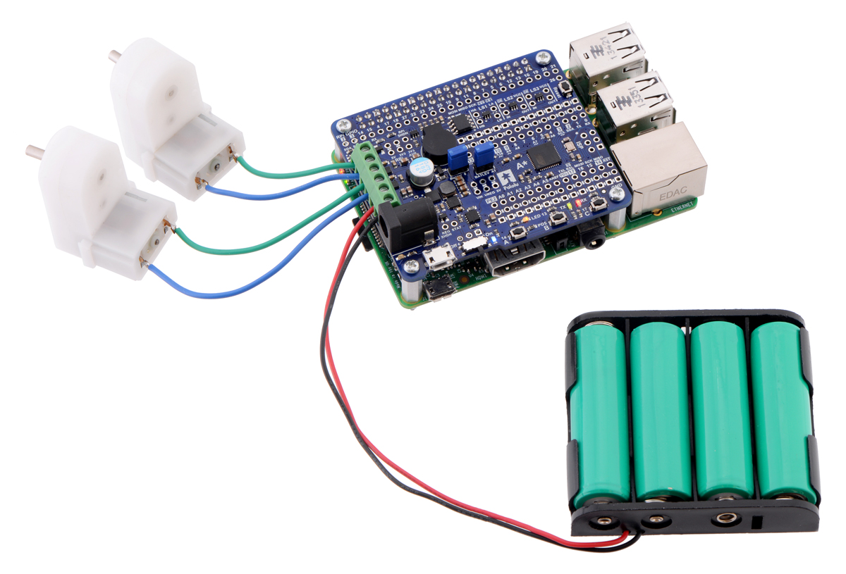
Driving motors with an A-Star 32U4 Robot Controller LV with Raspberry Pi Bridge on a
Raspberry Pi Model B+ or Pi 2 Model B.
Although the LV and SV versions of the robot controller use different driver ICs, the motor driver
interface is identical between the two versions. Four pins are used to control the drivers:
• Digital pin 12, or PD6, controls the direction of motor 1 (when LOW, motor current flows
from A to B; when HIGH, current flows from B to A).
• PE2 (which does not have an Arduino pin number) controls the direction of motor 2.
• Digital pin 9, or PB5, controls the speed of motor 1 with PWM (pulse width modulation)
generated by the ATmega32U4’s Timer1.
• Digital pin 10, or PB6, controls the speed of motor 2 with PWM.
The AStar32U4 library provides functions that allow you to easily control the motors.
Pololu A-Star 32U4 Robot Controller User’s Guide © 2001–2019 Pololu Corporation
3. A-Star 32U4 Robot Controller with Raspberry Pi Bridge Page 11 of 50

Maximum current and power dissipation considerations
The DRV8838 datasheet recommends a maximum continuous current of 1.8 A, and the robot
controller’s printed circuit board typically draws enough heat out of the motor driver chips to allow it to
sustain this amount of current. In our tests, we found that the chip was able to deliver 1.8 A for many
minutes without triggering a thermal shutdown. Our tests were conducted at 100% duty cycle with no
forced air flow; PWMing the motor will introduce additional heating proportional to the frequency.
Motor currents over 1.8 A will likely trip either the over-temperature or over-current protection of the
DRV8838. The current limiting threshold can be as low as 1.9 A or as high as 3.5 A. This limiting helps
prevent damage to the drivers if a motor draws too much current, although the reduced current output
will degrade motor performance.
Some situations can increase heating of the motor drivers and reduce their maximum available current
output, such as drawing a large amount of current from the A-Star’s 5 V regulator, mounting the board
on a Raspberry Pi, or using it in an enclosure that limits air flow. The actual current you can deliver will
depend on how well you can keep the motor drivers cool.
This product can get hot enough to burn you long before the chip overheats. Take care
when handling this product and other components connected to it.
3.4. SV motor drivers
The A-Star 32U4 Robot Controller SV features two Maxim MAX14870 motor drivers that can each
deliver a continuous 1.7 A (2.5 A peak). The motor power supply is derived from an external source
connected to the A-Star’s Power In terminals, which also feeds the on-board voltage regulator and
should have a voltage between 5.5 V and 36 V. (Although the MAX14870 works with motor supply
voltages as low as 4.5 V, the voltage regulator requires a minimum input voltage of 5.5 V.) For
more information about the drivers, see the MAX14870 datasheet [https://www.pololu.com/file/0J885/
MAX14870.pdf] (492k pdf). (We also sell a standalone carrier board [https://www.pololu.com/product/2961]
for this motor driver.)
The motor driver outputs, together with power pins, are connected to sets of through-holes along
the left side of the board. The larger holes are designed for 3.5 mm screw terminal blocks
[https://www.pololu.com/product/2444], which are soldered in on the assembled version. Alternatively, 0.1″
headers [https://www.pololu.com/product/965] can be used with the smaller holes on the SMT-only version,
or motor wires can be soldered directly to either set of holes.
Pololu A-Star 32U4 Robot Controller User’s Guide © 2001–2019 Pololu Corporation
3. A-Star 32U4 Robot Controller with Raspberry Pi Bridge Page 12 of 50

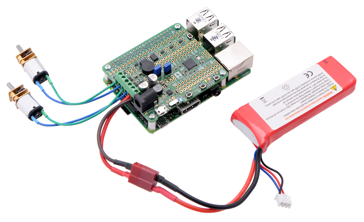
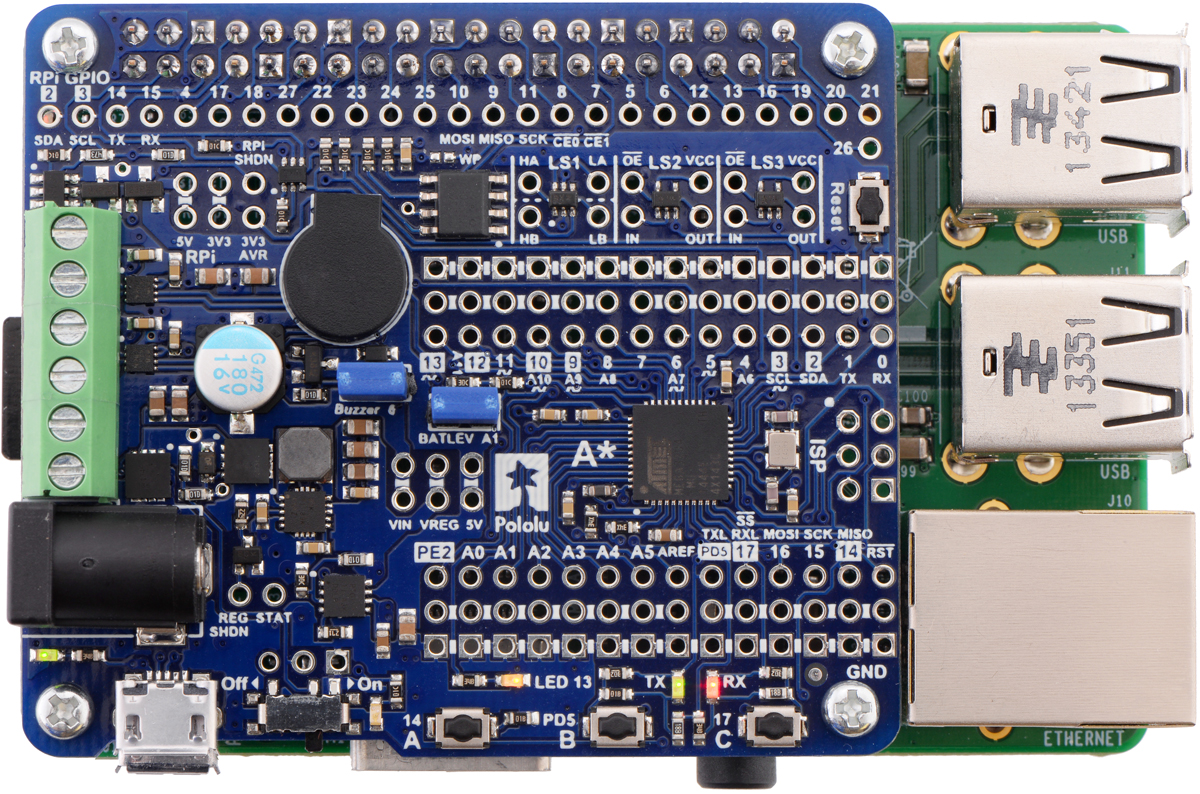
Driving motors with an A-Star 32U4 Robot Controller SV with Raspberry Pi Bridge on a
Raspberry Pi Model B+ or Pi 2 Model B.
Although the LV and SV versions of the robot controller use different driver ICs, the motor driver
interface is identical between the two versions. Four pins are used to control the drivers:
• Digital pin 12, or PD6, controls the direction of motor 1 (when LOW, motor current flows
from A to B; when HIGH, current flows from B to A).
• PE2 (which does not have an Arduino pin number) controls the direction of motor 2.
• Digital pin 9, or PB5, controls the speed of motor 1 with PWM (pulse width modulation)
generated by the ATmega32U4’s Timer1.
• Digital pin 10, or PB6, controls the speed of motor 2 with PWM.
The AStar32U4 library provides functions that allow you to easily control the motors.
Maximum current and power dissipation considerations
The MAX14870 datasheet recommends a maximum current of 2.5 A. However, the chip by itself will
typically overheat at lower currents. In our tests, we found that the chip was able to deliver 2.5 A for
only a few seconds before the chip’s thermal protection kicked in and disabled the motor outputs; a
continuous current of 1.7 A was sustainable for many minutes without triggering a thermal shutdown.
Our tests were conducted at 100% duty cycle with no forced air flow; PWMing the motor will introduce
Pololu A-Star 32U4 Robot Controller User’s Guide © 2001–2019 Pololu Corporation
3. A-Star 32U4 Robot Controller with Raspberry Pi Bridge Page 13 of 50

additional heating proportional to the frequency.
Some situations can increase heating of the motor drivers and reduce their maximum available current
output, such as drawing a large amount of current from the A-Star’s 5 V regulator, mounting the board
on a Raspberry Pi, or using it in an enclosure that limits air flow. The actual current you can deliver
will depend on how well you can keep the motor driver cool. The MAX14870 also has over-current
protection that triggers when the output current exceeds a certain limit (3 A minimum), which can help
prevent damage to the drivers if a motor draws too much current.
This product can get hot enough to burn you long before the chip overheats. Take care
when handling this product and other components connected to it.
3.5. Power
The A-Star 32U4 Robot Controller can be powered from an external voltage source, which is regulated
to 5 V by its on-board switching regulator; the provided voltage is also used to supply the motor drivers
directly. Alternatively, the A-Star’s USB connector can be used to provide 5 V only, leaving the motor
drivers unpowered.
An external supply should be be connected to the points labeled Power In (or PWR+ and GND).
These are power inputs with reverse-voltage protection that are controlled by the power switch.
Together with the motor outputs, these power inputs are connected to sets of through-holes along
the left side of the board. The larger holes are designed for 3.5 mm screw terminal blocks
[https://www.pololu.com/product/2444], while the smaller ones can be used with 0.1″ headers
[https://www.pololu.com/product/965]. A DC barrel jack [https://www.pololu.com/product/1139] can also be
used to provide power. On the assembled version of the board, a six-pin strip of 3.5 mm terminal
blocks and a barrel jack are soldered in for motor and power connections.
Warning: You must never connect different power sources to multiple Power In locations at
the same time, as doing so will create a short between the supplies.
The slide switch on the A* controls whether the external source is connected to the 5 V regulator and
motor drivers, providing a convenient way to switch off external power to the robot controller (and
optionally an attached Raspberry Pi) without unplugging any connections. The adjacent set of three
pins provides a place to connect your own power switch: to enable external power, connect the middle
pin to ground (accessible through the pin on the right).
When power is supplied through the Power In pins, the VIN pins can be used as an output to
supply reverse-protected and switched power to other devices. Alternatively, the external supply can
Pololu A-Star 32U4 Robot Controller User’s Guide © 2001–2019 Pololu Corporation
3. A-Star 32U4 Robot Controller with Raspberry Pi Bridge Page 14 of 50

be connected directly between VIN and GND, bypassing the reverse-voltage protection and power
switch.
One of the positive power inputs, labeled (PWR+), can optionally be reconfigured to serve as a
VIN access point instead. To do so, cut the surface-mount jumper on the underside of the board to
disconnect the PWR+ pad and the center pad, then use solder to bridge the VIN pad and the center
pad.
In a battery-powered application, it might be useful for the A-Star to monitor the battery’s voltage level.
The BATLEV pin provides access to a voltage divider that outputs one-third of the VIN voltage, and
this voltage can be read by connecting it to the adjacent analog pin 1 (A1) (or another analog input).
The readBatteryMillivoltsLV() and readBatteryMillivoltsSV() functions in the AStar32U4 library
can be used to determine the battery voltage from this reading.
5V regulator
VIN supplies power to a 5 V regulator, whose output is designated VREG. The allowable input voltage
range depends on the particular version of the A-Star 32U4 Robot Controller:
• LV: 2.7 V to 11 V (see Section 3.6 for regulator details)
• SV: 5.5 V to 36 V (see Section 3.7 for regulator details)
The regulator can be disabled by driving the regulator shutdown pin, REGSHDN, high; this will cause
5 V power to be sourced from USB instead if it is available.
Power selection
The A-Star 32U4 Robot Controller’s power selection circuit uses the TPS2113A power multiplexer
[https://www.pololu.com/product/2596] from Texas Instruments to choose whether its 5 V supply
(designated 5V) is sourced from USB or an external supply via the regulator, allowing both sources to
be connected at the same time and enabling the A* to safely and seamlessly transition between them.
The TPS2113A is configured to select external power unless the regulator output falls below about
4.5 V. If this happens, it will select the higher of the two sources, which will typically be the USB 5 V
bus voltage if the A* is connected to USB.
Consequently, when the A-Star is connected to a computer via USB, it will receive 5 V logic power
even when the power switch is off. This can be useful if you want to upload or test a program without
drawing power from batteries and without operating motors. It is safe to have USB connected and
external power switched on at the same time.
The currently selected source is indicated by the STAT pin in the middle of the board; this pin is
an open-drain output that is low if the external power source is selected and high-impedance if the
Pololu A-Star 32U4 Robot Controller User’s Guide © 2001–2019 Pololu Corporation
3. A-Star 32U4 Robot Controller with Raspberry Pi Bridge Page 15 of 50

USB supply is selected. The current limit of the TPS2113A is set to about 1.9 A nominally. For more
information about the power multiplexer, see the TPS2113A datasheet [https://www.pololu.com/file/0J771/
tps2113a.pdf] (1MB pdf).
Raspberry Pi power
By default, the robot controller will provide power from its 5V line to an attached Raspberry Pi. In this
situation, we recommend supplying external power through the Power In pins so that the Raspberry
Pi receives power from the A-Star’s on-board switching regulator. Alternatively, you can use a USB
wall power adapter [https://www.pololu.com/product/1459] to supply power through the A-Star’s USB
connector, although we have sometimes observed AVR brown-out resets occurring when the controller
is powering the Raspberry Pi this way. A typical computer USB port might not be able to supply enough
current to properly power the A-Star and an attached Raspberry Pi.
Power provided to the Raspberry Pi can be switched off by driving the Raspberry Pi shutdown pin,
RPISHDN, to 5 V.
An ideal diode circuit on the A* makes it safe to have a different power supply connected to the
Raspberry Pi (for example, through the Raspberry Pi’s USB Micro-B receptacle) while the A-Star 32U4
Robot Controller is connected and powered. (In other words, it is safe to have any combination of A-
Star USB power, A-Star external power, and Raspberry Pi USB power connected to the system.) The
RPI5V pin provides direct access to the Raspberry Pi’s 5 V line, which will typically come from the
higher of the two power sources.
Note that the diode circuit prevents power from being shared in the reverse direction: the Raspberry
Pi cannot supply 5 V logic power to the robot controller through the 40-pin connector.
3.3V supply for level shifters
Some of the level shifters on the A-Star are supplied with 3.3 V provided by an attached Raspberry
Pi, and this voltage is also accessible through the RPI3V3 pins. If you want to use the level shifters
in an application without a Raspberry Pi, you can instead supply them from the ATmega32U4
microcontroller’s integrated 3.3 V regulator by connecting the AVR3V3 pin to the adjacent RPI3V3 pin.
(It is preferable to use the Raspberry Pi’s 3.3 V supply when available because it is produced by a
switching regulator that is more efficient and can provide more current than the linear regulator in the
AVR.) Alternatively, you can supply a different voltage between 1.65 V and 5 V to the RPI3V3 pin to
make the level shifters shift to that voltage instead. See Section 3.8 for information about the level
shifters.
3.6. LV regulator
Pololu A-Star 32U4 Robot Controller User’s Guide © 2001–2019 Pololu Corporation
3. A-Star 32U4 Robot Controller with Raspberry Pi Bridge Page 16 of 50

The A-Star 32U4 Robot Controller LV can be
powered from a 2.7 V to 11 V external source. The
input voltage is regulated to 5 V by a TPS63061
switching step-up/step-down (buck-boost) converter
from Texas Instruments; although the regulator itself
works with input voltages up to 11.8 V, the motor
drivers limit the robot controller’s maximum input
voltage to 11 V. (We also make a standalone
regulator [https://www.pololu.com/product/2123] based on
this integrated circuit.)
The regulator’s flexibility in input voltage is especially
well-suited for battery-powered applications in which the battery voltage begins above 5 V and drops
below 5 V as the battery discharges. Without the typical restriction on the battery voltage staying
above 5 V throughout its life, a wider range of battery types can be considered. For example:
• A 4-cell battery holder, which might have a 6 V output with fresh alkalines or a 4.0 V output
with partially discharged NiMH cells, can be used to power this A*.
• A disposable 9 V battery powering the board can be discharged to under 3 V instead of
cutting out at 6 V, as with typical linear or step-down regulators.
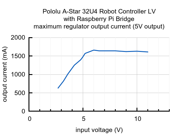
As shown in the left graph below, the LV’s switching regulator has an efficiency – defined as
(Power out)/(Power in) – of 80% to 90% for most combinations of input voltage and load.
The A-Star’s components, including the microcontroller and LEDs, draw 30 mA to 40 mA in typical
applications (without the buzzer). The rest of the regulator’s achievable output current, which depends
on input voltage as well as ambient conditions, can be used to power other devices; this can include an
attached Raspberry Pi (which typically draws a few hundred milliamps). The right graph above shows
output currents at which the voltage regulator’s over-temperature protection typically kicks in after a
few seconds. These currents represent the limit of the regulator’s capability and cannot be sustained
Pololu A-Star 32U4 Robot Controller User’s Guide © 2001–2019 Pololu Corporation
3. A-Star 32U4 Robot Controller with Raspberry Pi Bridge Page 17 of 50

for long periods; under typical operating conditions, a safe limit for the maximum continuous regulator
output current is 60% to 70% of the values shown in the graph.
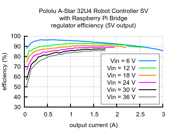
3.7. SV regulator
The A-Star 32U4 Robot Controller SV can be
powered from a 5.5 V to 36 V external source. The
input voltage is regulated to 5 V by an MP4423H
switching step-down (buck) converter from Monolithic
Power Systems. (We also make a standalone
regulator [https://www.pololu.com/product/2858] based on
this integrated circuit.)
As shown in the left graph below, the SV’s switching
regulator has an efficiency – defined as
(Power out)/(Power in) – of 80% to 95% for most
combinations of input voltage and load.
The A-Star’s components, including the microcontroller and LEDs, draw 30 mA to 40 mA in typical
applications (without the buzzer). The rest of the regulator’s achievable output current, which depends
on input voltage as well as ambient conditions, can be used to power other devices; this can include
an attached Raspberry Pi (which typically draws a few hundred milliamps). The right graph above
shows the output currents where the regulator’s output voltage drops below 4.75 V. These currents
are close to the limits of the regulator’s capability and generally cannot be sustained for long periods;
under typical operating conditions, a safe limit for the maximum continuous regulator output current is
60% to 70% of the values shown in the graph.
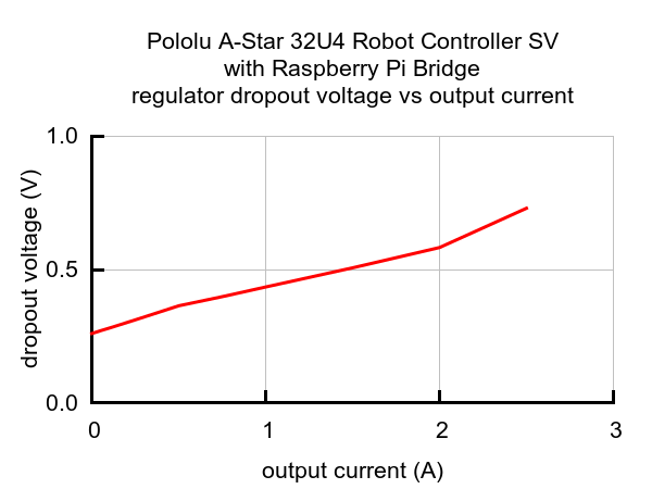
The dropout voltage of a step-down regulator is defined as the minimum amount by which the input
voltage much exceed the regulator’s target output voltage in order to assure the target output can
be achieved. As can be seen in the graph below, the dropout voltage of the Robot Controller SV’s
regulator increases approximately linearly with the output current. For light loads where the dropout
Pololu A-Star 32U4 Robot Controller User’s Guide © 2001–2019 Pololu Corporation
3. A-Star 32U4 Robot Controller with Raspberry Pi Bridge Page 18 of 50

voltage is small, the board can operate almost down to 5 V. However, for larger loads, the dropout
voltage should be taken into consideration when selecting a power supply; operating above 6 V will
ensure the full output current is available.
Typical dropout voltage of the 5 V regulator
on the A-Star 32U4 Robot Controller SV with
Raspberry Pi Bridge.
Note: Although the MP4423H is rated for a maximum operating input voltage of 36 V, it is
not appropriate to power the Robot Controller SV with a 36 V battery, as battery voltages
can be much higher than nominal voltages when they are charged. The maximum nominal
battery voltage we recommend is 24 V, and if you approach that limit, you should take extra
precautions to prevent LC voltage spikes from damaging the board (see this application
note [https://www.pololu.com/docs/0J16] for more information). A good practice is to ensure that
the A-Star’s power switch is off before connecting it to a voltage source.
3.8. Raspberry Pi interface and level shifters
The A-Star 32U4 Robot Controller with Raspberry Pi Bridge can be used as an expansion board
on top of a Raspberry Pi single-board computer. It conforms to the Raspberry Pi HAT (Hardware
Attached on Top) specification and is designed to connect to the Model B+ and newer versions of the
Raspberry Pi with 40-pin GPIO headers (including the Raspberry Pi 3 Model B [https://www.pololu.com/
product/2759] and Model A+ [https://www.pololu.com/product/2760]). A 2×20-pin 0.1″ female header
[https://www.pololu.com/product/1037] is soldered to the assembled version of the robot controller, and
it ships with a set of four standoffs [https://www.pololu.com/product/1952], screws [https://www.pololu.com/
product/1968], and nuts [https://www.pololu.com/product/1967]. (The header and mounting hardware are
not included with the SMT-only version, but you can solder in either a standard or stackable
[https://www.pololu.com/product/2748] header yourself.)
Pololu A-Star 32U4 Robot Controller User’s Guide © 2001–2019 Pololu Corporation
3. A-Star 32U4 Robot Controller with Raspberry Pi Bridge Page 19 of 50

I²C communication
When used as a Raspberry Pi add-on, the A-Star is designed to serve as an auxiliary controller,
communicating with the Raspberry Pi using an I²C interface (also known as 2-wire Serial Interface,
or TWI). As such, the ATmega32U4 microcontroller’s I²C data and clock lines (SDA and SCL) are
connected to the corresponding lines on the Raspberry Pi’s I²C bus 1 through on-board level-shifting
circuits. These bidirectional level shifters convert between the AVR’s 5 V logic level and the Raspberry
Pi’s 3.3 V logic level.
We have written an Arduino library [https://github.com/pololu/pololu-rpi-slave-arduino-library] for the robot
controller that lets it act as an I²C slave and provides a framework for communication between
the A-Star and a Raspberry Pi master. A tutorial [https://www.pololu.com/blog/577] on the Pololu blog
demonstrates this library and its included example code, using them to make a robot that can be
remotely controlled and monitored through a web server running on the Raspberry Pi.
Pololu A-Star 32U4 Robot Controller User’s Guide © 2001–2019 Pololu Corporation
3. A-Star 32U4 Robot Controller with Raspberry Pi Bridge Page 20 of 50
/


