Page is loading ...

Pololu Zumo Shield for
Arduino User’s Guide
Pololu Zumo Shield for Arduino User’s Guide © 2001–2019 Pololu Corporation
https://www.pololu.com/docs/0J57/all Page 1 of 52

1. Overview . . . . . . . . . . . . . . . . . . . . . . . . . . . . . . . . . . . . . . . . . . . . . . 3
1.a. Contacting Pololu . . . . . . . . . . . . . . . . . . . . . . . . . . . . . . . . . . . . . . 4
1.b. Included components . . . . . . . . . . . . . . . . . . . . . . . . . . . . . . . . . . . . 5
2. Assembly . . . . . . . . . . . . . . . . . . . . . . . . . . . . . . . . . . . . . . . . . . . . . . 8
2.a. What you will need . . . . . . . . . . . . . . . . . . . . . . . . . . . . . . . . . . . . . 8
2.b. Assembling the Zumo Shield and chassis . . . . . . . . . . . . . . . . . . . . . . . . . . 9
2.c. Adding a Zumo reflectance sensor array (optional) . . . . . . . . . . . . . . . . . . . . 23
3. The Zumo Shield in detail . . . . . . . . . . . . . . . . . . . . . . . . . . . . . . . . . . . . 30
3.a. Features and components . . . . . . . . . . . . . . . . . . . . . . . . . . . . . . . . . 30
3.b. Front expansion . . . . . . . . . . . . . . . . . . . . . . . . . . . . . . . . . . . . . . 33
3.c. Jumper settings . . . . . . . . . . . . . . . . . . . . . . . . . . . . . . . . . . . . . . 34
3.d. Inertial sensors (accelerometer, magnetometer, and gyro) . . . . . . . . . . . . . . . . 36
4. Schematic diagrams . . . . . . . . . . . . . . . . . . . . . . . . . . . . . . . . . . . . . . . 39
5. Arduino pin assignment table . . . . . . . . . . . . . . . . . . . . . . . . . . . . . . . . . . 40
6. Zumo Shield Arduino library . . . . . . . . . . . . . . . . . . . . . . . . . . . . . . . . . . . 41
7. Example sketches . . . . . . . . . . . . . . . . . . . . . . . . . . . . . . . . . . . . . . . . 44
7.a. RC Zumo . . . . . . . . . . . . . . . . . . . . . . . . . . . . . . . . . . . . . . . . . 44
7.b. Simple border-detecting sumo robot . . . . . . . . . . . . . . . . . . . . . . . . . . . 45
7.c. Collision-detecting sumo robot . . . . . . . . . . . . . . . . . . . . . . . . . . . . . . 47
7.d. Line follower . . . . . . . . . . . . . . . . . . . . . . . . . . . . . . . . . . . . . . . . 47
7.e. Maze solver . . . . . . . . . . . . . . . . . . . . . . . . . . . . . . . . . . . . . . . . 47
7.f. Using the compass . . . . . . . . . . . . . . . . . . . . . . . . . . . . . . . . . . . . . 48
8. Controlling a servo . . . . . . . . . . . . . . . . . . . . . . . . . . . . . . . . . . . . . . . . 49
8.a. Controlling a servo with an Arduino Uno . . . . . . . . . . . . . . . . . . . . . . . . . 49
8.b. Controlling a servo with an Arduino Leonardo or A-Star 32U4 Prime . . . . . . . . . . . 51
Pololu Zumo Shield for Arduino User’s Guide © 2001–2019 Pololu Corporation
Page 2 of 52

1. Overview
The Zumo Shield provides a convenient interface between our Zumo chassis [https://www.pololu.com/
product/1418] and an A-Star 32U4 Prime [https://www.pololu.com/category/165/a-star-32u4-prime], Arduino
Uno [https://www.pololu.com/product/2191], or Arduino Leonardo [https://www.pololu.com/product/2192] (it is
not compatible with the Arduino Mega or Due, but it can be used with older Arduinos that have the
same form factor as the Uno, such as the Duemilanove). The shield mounts directly to the chassis,
connecting to its battery terminals and motors, and the Arduino plugs into the shield’s male header
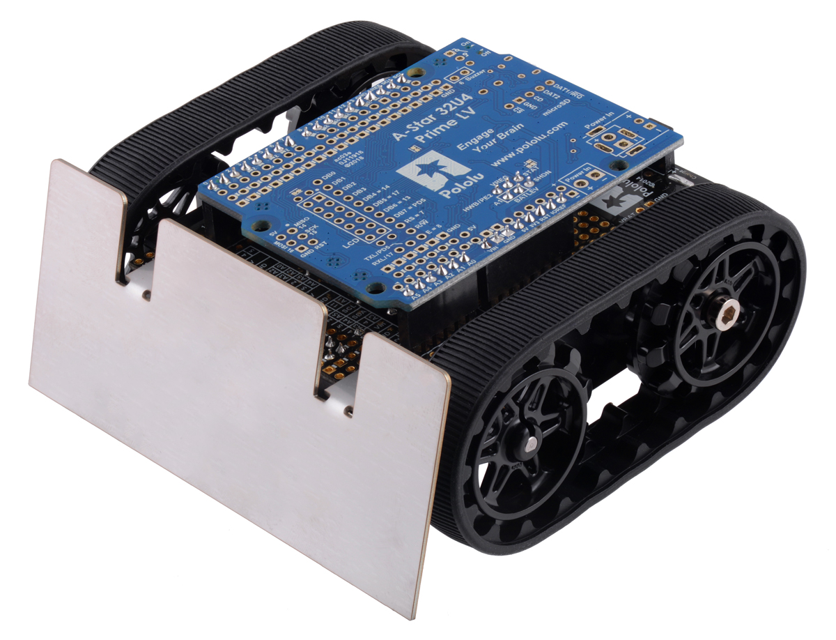
pins, face down. The shield provides all the electronics necessary to power the motors and includes
some additional fun components for making a more interesting robot, such as a buzzer for making
sounds and inertial sensors including an accelerometer and gyro.
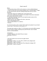
Zumo Shield for Arduino, v1.2, as it
ships (assembled with surface-mount
components only).
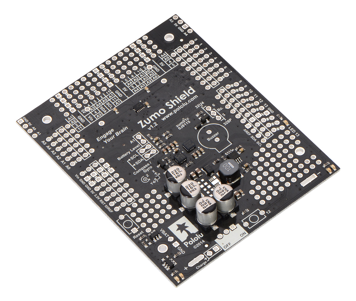
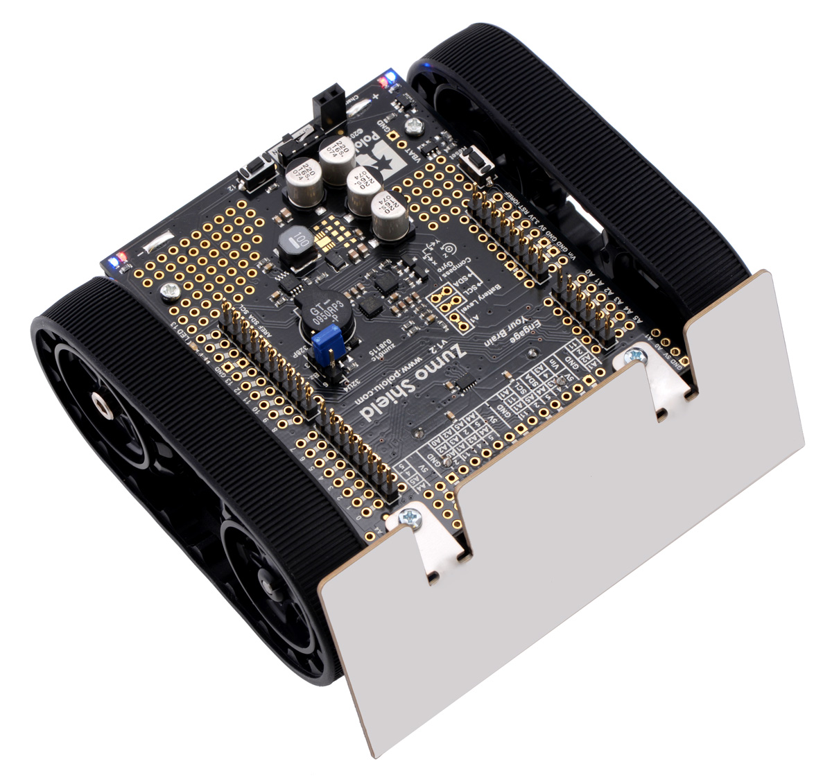
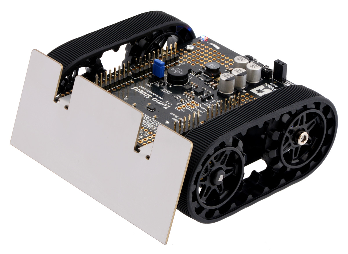
Assembled Zumo Robot for Arduino
with an Arduino-compatible A-Star
32U4 Prime LV.
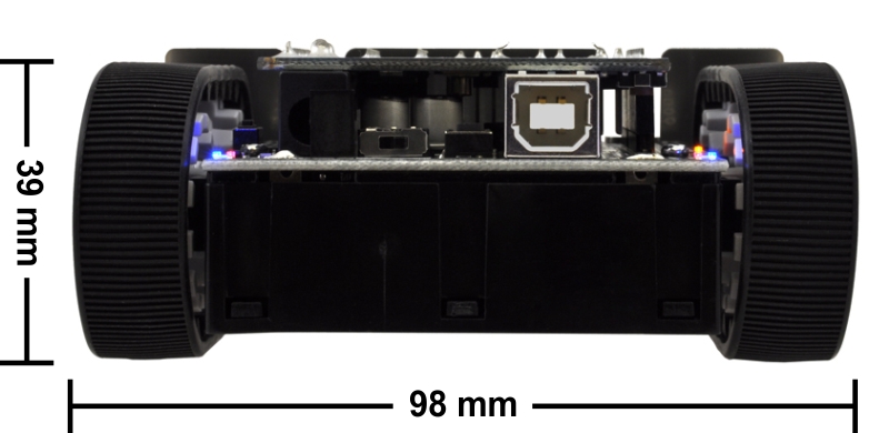
A Zumo chassis, Zumo Shield, and Arduino (or compatible board) can be combined to become a low-
profile, Arduino-controlled tracked robot that is less than 10 cm on each side (small enough to qualify
for Mini-Sumo competitions).
Main features of the Zumo Shield for
Arduino, v1.2.
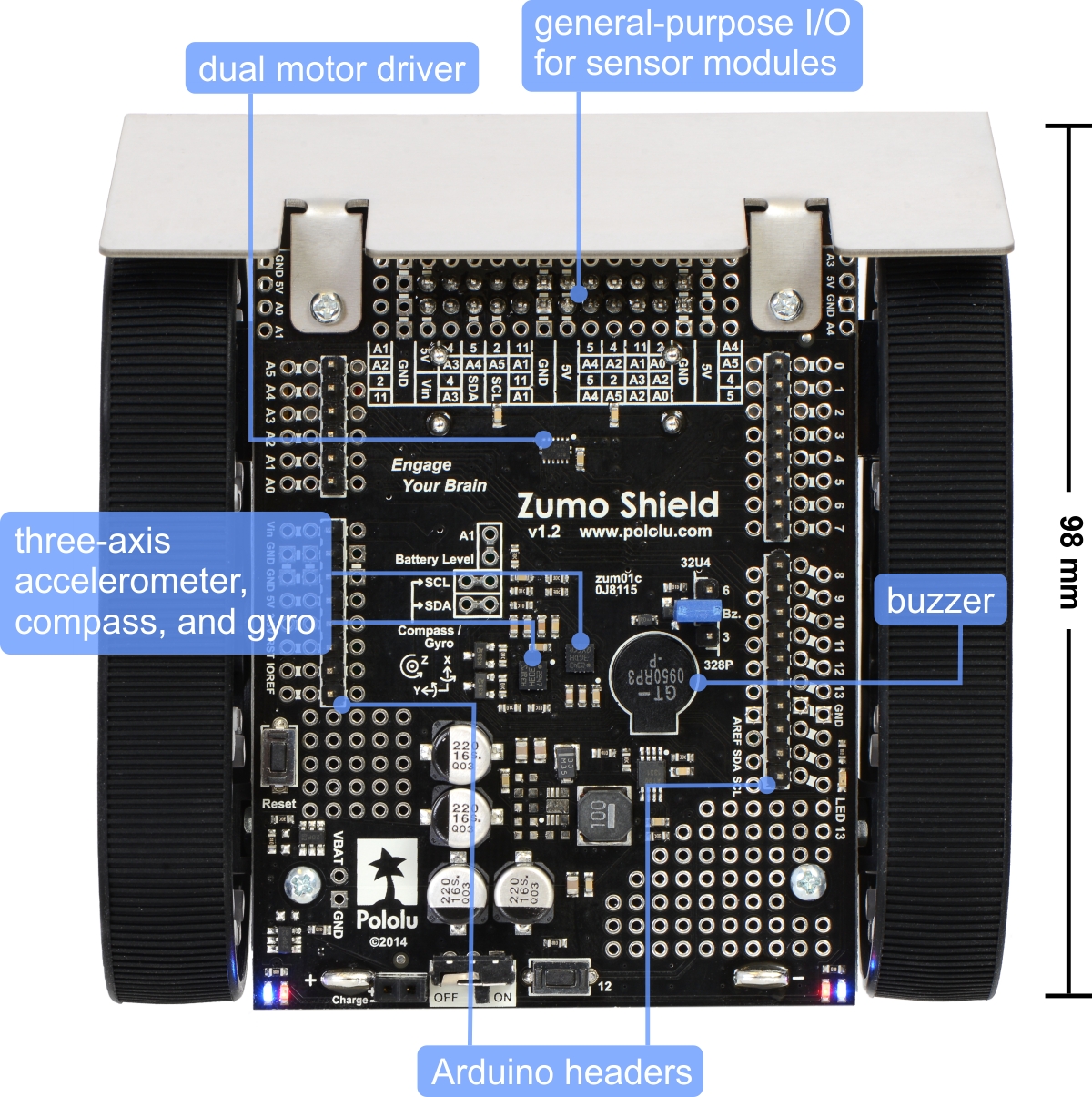
Zumo robot assembled with a Zumo
Shield and Arduino Uno, back view.
Pololu Zumo Shield for Arduino User’s Guide © 2001–2019 Pololu Corporation
1. Overview Page 3 of 52

Zumo Robot for Arduino, v1.2.
The latest revision of the Zumo Shield is version 1.2. This version adds an L3GD20H
[https://www.pololu.com/product/2129] 3-axis gyroscope and upgrades the accelerometer and
magnetometer chip to the newer LSM303D [https://www.pololu.com/product/2127]. It is available by itself,
as part of a kit, or in a complete robot:
• Zumo Shield, v1.2 [https://www.pololu.com/product/2508]
• Zumo robot kit for Arduino, v1.2 [https://www.pololu.com/product/2509] with a Zumo chassis
[https://www.pololu.com/product/1418] and a stainless steel Zumo blade [https://www.pololu.com/
product/1410]
• Zumo robot for Arduino, v1.2 [https://www.pololu.com/product/2510], fully assembled with 75:1
HP motors [https://www.pololu.com/product/2361] and a reflectance sensor array
[https://www.pololu.com/product/1419] installed.
The information in this user’s guide also applies to the original Zumo Shield, which did not have a gyro
and featured an LSM303DLHC [https://www.pololu.com/product/2124] accelerometer and magnetometer:
• Zumo Shield [https://www.pololu.com/product/2504]
• Zumo robot kit for Arduino [https://www.pololu.com/product/2505]
• Zumo robot for Arduino [https://www.pololu.com/product/2506]
July 10, 2015 update: The Zumo Robot for Arduino now features black, spoked sprockets
in place of the original white ones (which can still be seen in some of the pictures in this
guide).
1.a. Contacting Pololu
We would be delighted to hear from you about your experiences
with the Zumo Shield for Arduino [https://www.pololu.com/product/
2508], Zumo robot kit for Arduino [https://www.pololu.com/product/
2509], or Zumo robot for Arduino [https://www.pololu.com/product/
2510]. If you need technical support or have any feedback you
would like to share, you can contact us [https://www.pololu.com/
contact] directly or post on our forum [http://forum.pololu.com/
viewforum.php?f=29]. Tell us what we did well, what we could
improve, what you would like to see in the future, or anything else
you would like to say!
Pololu Zumo Shield for Arduino User’s Guide © 2001–2019 Pololu Corporation
1. Overview Page 4 of 52

1.b. Included components
The Zumo Shield is available:
• by itself [https://www.pololu.com/product/2508];
• as part of a Zumo robot kit for Arduino [https://www.pololu.com/product/2509] that also includes
a Zumo chassis [https://www.pololu.com/product/1418] and a stainless steel Zumo blade
[https://www.pololu.com/product/1410]; or
• as a fully-assembled Zumo robot for Arduino [https://www.pololu.com/product/2510] with 75:1
HP motors [https://www.pololu.com/product/2361] and a reflectance sensor array
[https://www.pololu.com/product/1419] installed.
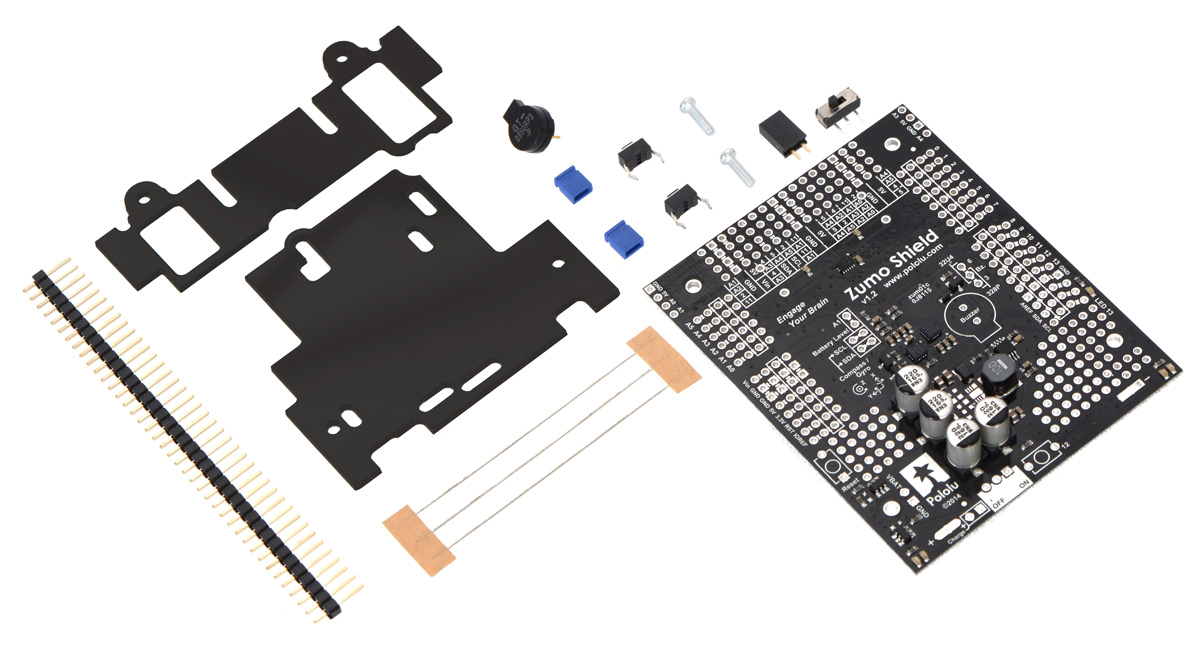
Zumo Shield
The shield itself comes with the following
components:
• right-angle slide switch
• two pushbuttons
[https://www.pololu.com/product/1400]
• buzzer
• 2-pin battery-charging header
[https://www.pololu.com/product/1012]
• three jumper wires (for soldering
motors to the shield)
• two 25-pin 0.1″ straight breakaway
male headers [https://www.pololu.com/
product/965]
• four blue shorting blocks
[https://www.pololu.com/product/968]
• two 5/16″ #2-56 machine screws (to be
used instead of the 1/4″ screws
included with the chassis kit if you
attach a Zumo blade)
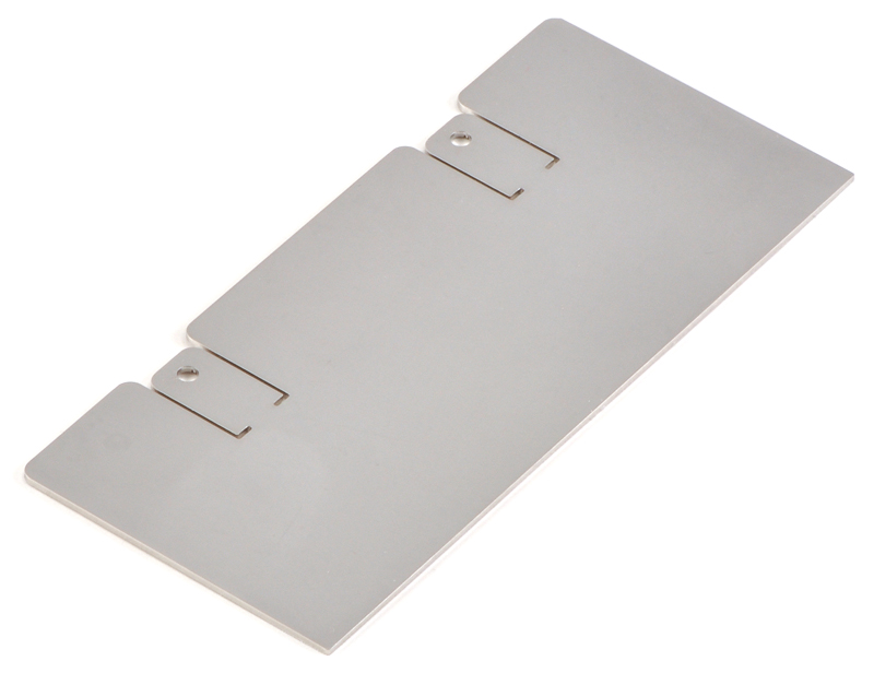
• 1/16″ black acrylic spacer plate (two
pieces)
Pololu Zumo Shield for Arduino User’s Guide © 2001–2019 Pololu Corporation
1. Overview Page 5 of 52

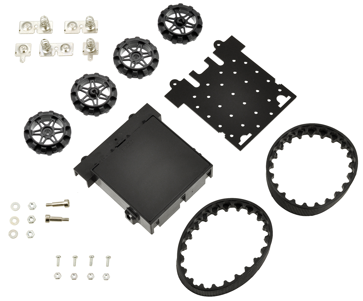
Zumo Robot Kit for Arduino
In addition to the shield and its included hardware, the Zumo robot kit for Arduino also includes these
components:
• Zumo chassis kit
[https://www.pololu.com/product/1418],
which includes:
◦ Zumo chassis main body
◦ 1/16″ black acrylic mounting
plate (not used with the Zumo
Shield)
◦ Two drive sprockets
◦ Two idler sprockets
◦ Two 22-tooth silicone tracks
◦ Two shoulder bolts with
washers and M3 nuts
◦ Four 1/4″ #2-56 screws and
nuts
◦ Battery terminals
• Basic sumo blade for Zumo chassis [https://www.pololu.com/
product/1410]
You will receive the black acrylic spacer and mounting plates with protective paper
masking on both sides. You can peel this masking off to expose the acrylic surface, or
you can leave it on to increase the thickness of the plates.
The shield and chassis kit include extra parts like jumper wires, screws, nuts, and
washers, so do not be concerned if you have some leftover hardware after assembling
your Zumo.
Pololu Zumo Shield for Arduino User’s Guide © 2001–2019 Pololu Corporation
1. Overview Page 6 of 52

Zumo Robot for Arduino
The Zumo robot for Arduino is a fully-assembled
robot platform built from the same components
found in the Zumo robot kit for Arduino, along
with these additions:
• Two 75:1 HP micro metal gearmotors
[https://www.pololu.com/product/2361]
• Zumo reflectance sensor array
[https://www.pololu.com/product/1419]
Pololu Zumo Shield for Arduino User’s Guide © 2001–2019 Pololu Corporation
1. Overview Page 7 of 52

2. Assembly
If you have a Zumo robot kit for Arduino [https://www.pololu.com/product/2509] or a separate Zumo
Shield [https://www.pololu.com/product/2508] and chassis [https://www.pololu.com/product/1418], this section
will guide you through assembling them into a complete robot.
If you purchased an assembled Zumo robot for Arduino [https://www.pololu.com/product/2510], this
assembly work has been done for you, although you might want to configure your Zumo by adding or
removing some jumper connections [https://www.pololu.com/docs/0J57/3.c]. Otherwise, you can simply
install four AA batteries and an Arduino (or compatible controller) and skip to Section 3 to start
learning how to use your Zumo!
2.a. What you will need
The Zumo Shield is designed to be mounted on a Zumo chassis kit [https://www.pololu.com/product/
1418], which is included (along with a Zumo blade [https://www.pololu.com/product/1410]) if you have a
Zumo robot kit for Arduino [https://www.pololu.com/product/2509]. In addition, you will require these
items to construct a working Arduino-controlled Zumo robot:
Additional required components
• Two micro metal gearmotors [https://www.pololu.com/category/60/micro-metal-gearmotors] (we
recommend 100:1, 75:1, or 50:1 gear ratio versions with HP [https://www.pololu.com/category/
173/6v-high-power-hp-micro-metal-gearmotors] or HPCB [https://www.pololu.com/category/174/6v-high-
power-carbon-brush-hpcb-micro-metal-gearmotors] motors). The pre-assembled version of the
Zumo robot [https://www.pololu.com/product/2510] includes two 75:1 HP [https://www.pololu.com/
product/2361] micro metal gearmotors.
• An Arduino or compatible board (we recommend an A-Star 32U4 Prime
[https://www.pololu.com/category/165/a-star-32u4-prime], Arduino Uno R3 [https://www.pololu.com/
product/2191], or Arduino Leonardo [https://www.pololu.com/product/2192])
• Four AA batteries (we recommend rechargeable AA NiMH cells [https://www.pololu.com/
product/1003])
Please see the product description for the chassis kit [https://www.pololu.com/product/1418] for more
information and recommendations about selecting these components.
Additional optional components
• Zumo reflectance sensor array [https://www.pololu.com/product/1419]
• Basic sumo blade for the Zumo chassis [https://www.pololu.com/product/1410]
• Sensors [https://www.pololu.com/category/7/sensors], such as our QTR reflectance sensors
Pololu Zumo Shield for Arduino User’s Guide © 2001–2019 Pololu Corporation
2. Assembly Page 8 of 52

[https://www.pololu.com/category/123/pololu-qtr-reflectance-sensors]
• Connectors and jumper wires [https://www.pololu.com/category/19/connectors], for connecting
additional sensors and components
• Battery charger (such as the iMAX-B6AC [https://www.pololu.com/product/2588]), if you are using
rechargeable batteries
Assembly tools
• Soldering iron and solder (we recommend one with adjustable temperature control)
• Wire cutter
• Small Phillips screwdriver
• 3 mm Allen wrench (hex key)
• long-nose pliers (for bending the Zumo blade mounting tabs)
2.b. Assembling the Zumo Shield and chassis
Please follow these instructions carefully to assemble your Zumo Shield and chassis properly. (These
pictures show the original Zumo Shield [https://www.pololu.com/product/2504], but the assembly process
is the same for the latest v1.2 version [https://www.pololu.com/product/2508].)
Pololu Zumo Shield for Arduino User’s Guide © 2001–2019 Pololu Corporation
2. Assembly Page 9 of 52

Through-hole parts
1. Solder the included through-hole components to the shield:
◦ power switch
◦ reset pushbutton
◦ user pushbutton
◦ buzzer
◦ charging connector (1×2-pin female header)
2. On the bottom of the board, trim any leads longer than 1/16″ (the thickness of the spacer
plate) so they do not prevent the shield from sitting flat on the spacer plate and chassis.
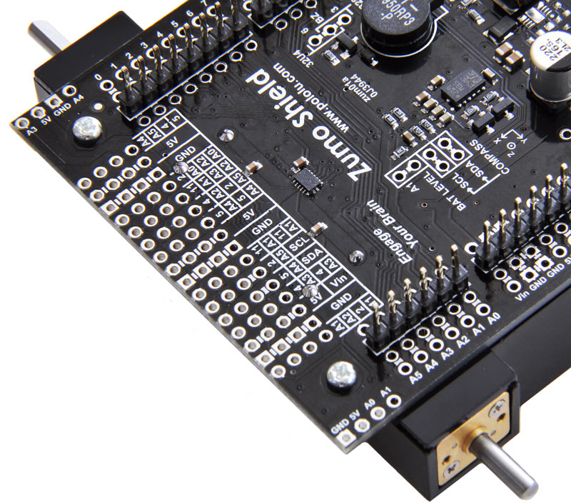
Arduino headers
3. Separate the 1×40-pin breakaway male header into the appropriate segments for connecting
your Arduino and solder them to the shield. These header segments should be soldered to
the sets of holes outlined with white rectangles on the top of the shield, with the pins facing
up.
The A-Star 32U4 Primes and the newest Arduino boards, including the Uno R3 and the Leonardo, use
Pololu Zumo Shield for Arduino User’s Guide © 2001–2019 Pololu Corporation
2. Assembly Page 10 of 52

one 1×10 header, two 1×8 headers, and one 1×6 header; older Arduino boards use two 1×8 headers
and two 1×6 headers (the two pairs of pins highlighted above in red should not be populated if you are
using this board with an older Arduino that does not support these additional pins). Please make sure
you solder the appropriate headers for your particular Arduino!
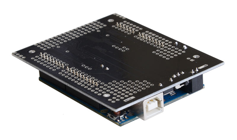
An easy way to line up the Arduino headers for soldering is to plug them into an Arduino, then place
the shield upside-down on top of them, as shown in the picture below. Be careful to insert the header
pins into the correct set of holes before you begin soldering. Note: if you use this alignment technique,
make sure your soldering iron temperature is not excessively hot and avoid holding the iron on a single
pin for more than a few seconds as this could melt the Arduino’s female headers.
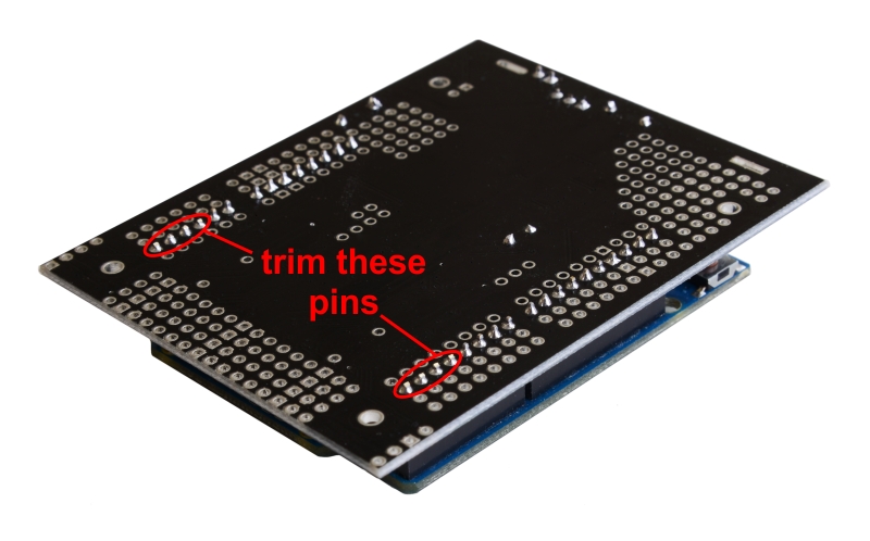
4. On the bottom of the board, trim the four Arduino header pins closest to the front of the board
on each side to prevent them from contacting the motor housings. If you think there is a
chance these pins might still touch the motor cases, you can put some electrical tape on the
motors to act as insulation.
Pololu Zumo Shield for Arduino User’s Guide © 2001–2019 Pololu Corporation
2. Assembly Page 11 of 52

Jumpers and additional connections
5. Optional: If you want to enable the buzzer, enable the battery level input, or disable the
compass, now is a good time to add and/or cut jumper connections to configure the shield to
your liking. This can also be done later, though soldering to these pins is more difficult once
the robot is assembled (especially if you decide later you want to add header pins for use
with shorting blocks; this would require a lot of disassembly). The jumpers are explained in
detail in Section 3.c. The buzzer and battery level jumpers can be connected by soldering
in a short piece of wire between the two holes, while the compass I²C connections can be
broken by cutting the trace on the top of the board between the holes. Note: there is not
enough clearance to use male headers on the battery level and compass I²C jumpers if you
are using an Arduino with a DIP (through-hole) microcontroller.
Instead of making a wire connection, you can solder a 1×3 male header to the buzzer
jumper holes to allow the use of a shorting block for connecting the buzzer. You can
also use male headers and shorting blocks for the battery level jumper and compass
jumpers if you have an Arduino Uno with an SMD (surface mount) microcontroller,
Arduino Leonardo, or A-Star 32U4 Prime. However, there is not enough clearance to use
male headers on the battery level and compass I²C jumpers if you are using an Arduino
with a DIP (through-hole) microcontroller.
Pololu Zumo Shield for Arduino User’s Guide © 2001–2019 Pololu Corporation
2. Assembly Page 12 of 52

6. Optional: At this point, you might consider soldering additional components (such as
sensors), or headers or wires for connecting them, to the shield. If you do this, please check
to make sure your part placement does not interfere with the shield’s ability to mate with the
Arduino or the chassis. In particular, note that only components in the outermost three rows
of the front expansion area can extend below the board (the fourth front-expansion row can
only be used for pins extending above the board), and if you add any through-hole parts to
the prototyping areas on the shield, you will need to drill corresponding holes in the acrylic
spacer plate for the leads to fit into.
Motors and drive sprockets
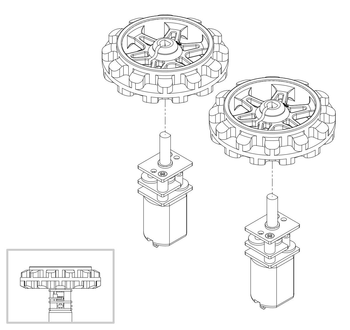
7. Press the output shafts of the motors into the drive sprockets, with the raised lip on one side
of the sprocket facing away from the motor (as shown below). The end of the gearbox shaft
should end up flush with the outside of the sprocket. A good way to do this is to set the wheel
on flat surface (like a table top) and press the motor shaft into the wheel until it contacts the
surface.
Pololu Zumo Shield for Arduino User’s Guide © 2001–2019 Pololu Corporation
2. Assembly Page 13 of 52

8. Cut two of the included jumper wires in half to form four segments, and trim off the ends
that are covered in adhesive (the adhesive could interfere with making a good electrical
connection to the motor). These wire segments will be used as motor leads.
9. Solder a pair of leads to each motor in the orientation described below. You might find it
helpful to make a small bend at the tip of each lead to hook into the hole in the motor lead tab
to hold it in place for soldering. Warning: holding the soldering iron against the motor lead
for more than a few seconds can start to damage the motor brushes, so try to be reasonably
quick/efficient with this soldering; if the first attempt does not go well, remove the soldering
iron and let the motor cool for a few seconds before trying again.
Pololu Zumo Shield for Arduino User’s Guide © 2001–2019 Pololu Corporation
2. Assembly Page 14 of 52

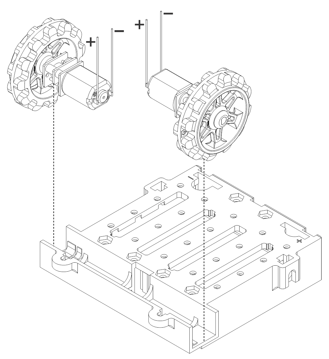
Each motor’s positive terminal is indicated by a plus sign (+) in the black plastic end of the motor,
as indicated in the picture below. The motors should be soldered into the shield with the positive
terminal closest to the front, so you should attach the leads to allow the motors to be oriented this way.
(However, don’t worry if you accidentally get the orientation of one or both motors wrong. You can later
compensate for it in software with our Zumo Shield Arduino library [https://www.pololu.com/docs/0J57/
6].)
10. Place the motors into the channel in the front of the chassis, aligning the gearbox with the
grooves in the channel. The front plate of the gearbox should be even with the edge of the
chassis.
Pololu Zumo Shield for Arduino User’s Guide © 2001–2019 Pololu Corporation
2. Assembly Page 15 of 52

Chassis and shield
To assemble the chassis with the Zumo Shield, you should use the two-piece acrylic
spacer plate that is included with the shield. You will not need the one-piece mounting
plate that is included with the Zumo chassis.
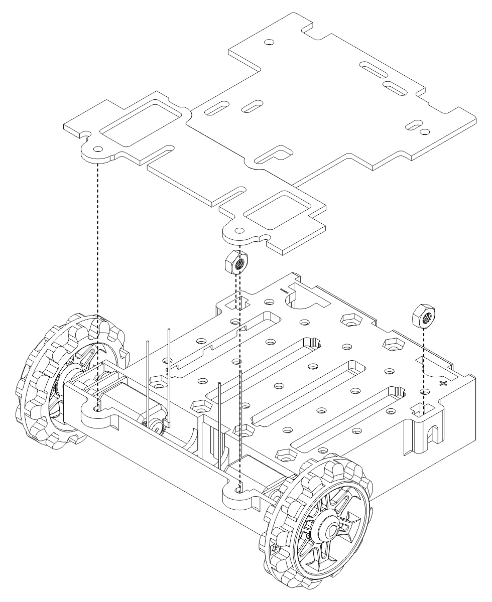
11. Place an M3 nut in each of the two side slots near the rear of the chassis. The slots are sized
so that nuts will not be able to rotate within them. (These nuts will be used to mount the idler
sprockets later.)
12. If you want, peel the protective paper masking off both sides of the acrylic spacer plate
pieces. Alternatively, you can leave the masking on for additional thickness. If you leave the
masking on, it will be mostly concealed when the robot is fully assembled.
13. Cover the chassis and motors with the spacer plate pieces and then the Zumo shield. The
Pololu Zumo Shield for Arduino User’s Guide © 2001–2019 Pololu Corporation
2. Assembly Page 16 of 52

holes in the spacer plate should line up with the through-holes in the shield resting on top
of it, and the motor leads should be aligned so they pass through the slots in the spacer as
shown in the picture below. There is only one correct orientation for these plates. (The plate
consists of two separate pieces to make it possible to disassemble the Zumo without having
to desolder the motors or battery terminals.)
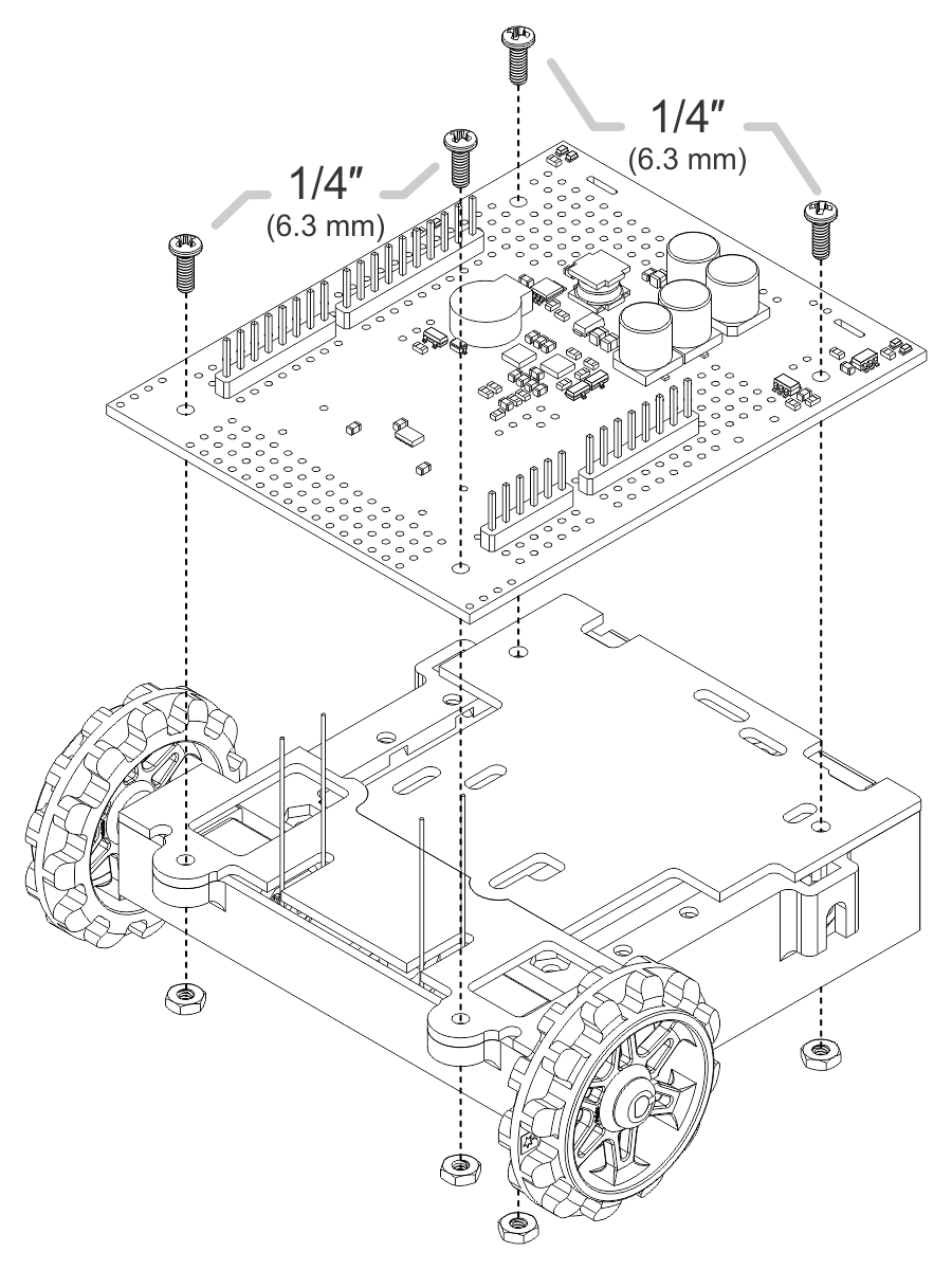
14. In each of the four mounting holes, insert a #2-56 machine screw through the shield, spacer
plate, and chassis, and tighten it against a nut under the chassis. It is usually easier to place
the nut into the recess first and hold it there with a finger or piece of tape while inserting the
screw. Note that the kit includes two different sizes of #2-56 machine screws: 1/4″and 5/16″.
The two longer screws are intended for use in the front holes (near the motors) if you are also
Pololu Zumo Shield for Arduino User’s Guide © 2001–2019 Pololu Corporation
2. Assembly Page 17 of 52

mounting a sumo blade; otherwise, you can use the shorter 1/4″ screws for all four mounting
holes.
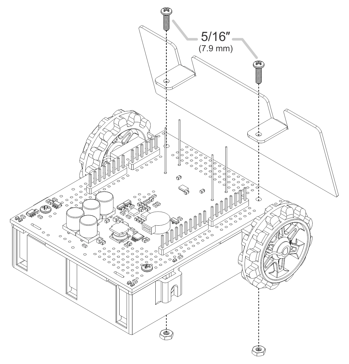
If you are also adding a basic sumo blade, you can either mount it now or add it later after you are
done soldering the motors and battery contacts. (Note: If you intend to solder anything to the front
expansion area of the shield, such as a Zumo reflectance sensor array, you will have more room to
work if you do the soldering before adding the sumo blade.)
To install the blade, first bend its mounting tabs to the appropriate angle. Next, place them on top of
Pololu Zumo Shield for Arduino User’s Guide © 2001–2019 Pololu Corporation
2. Assembly Page 18 of 52

the shield so that the holes line up with the two front mounting holes and insert the two longer (5/16″)
#2-56 machine screws (included with the shield) through the blade, shield, spacer plate, and chassis.
Be careful when adjusting the angle of the sumo blade while it is mounted to the chassis, as this can
crack the acrylic spacer plate if you apply sudden or excessive force. We recommend you do not try
bending the blade while it is mounted to the chassis.
15. Solder each motor lead to the shield, then trim off the excess length of wire.
Pololu Zumo Shield for Arduino User’s Guide © 2001–2019 Pololu Corporation
2. Assembly Page 19 of 52

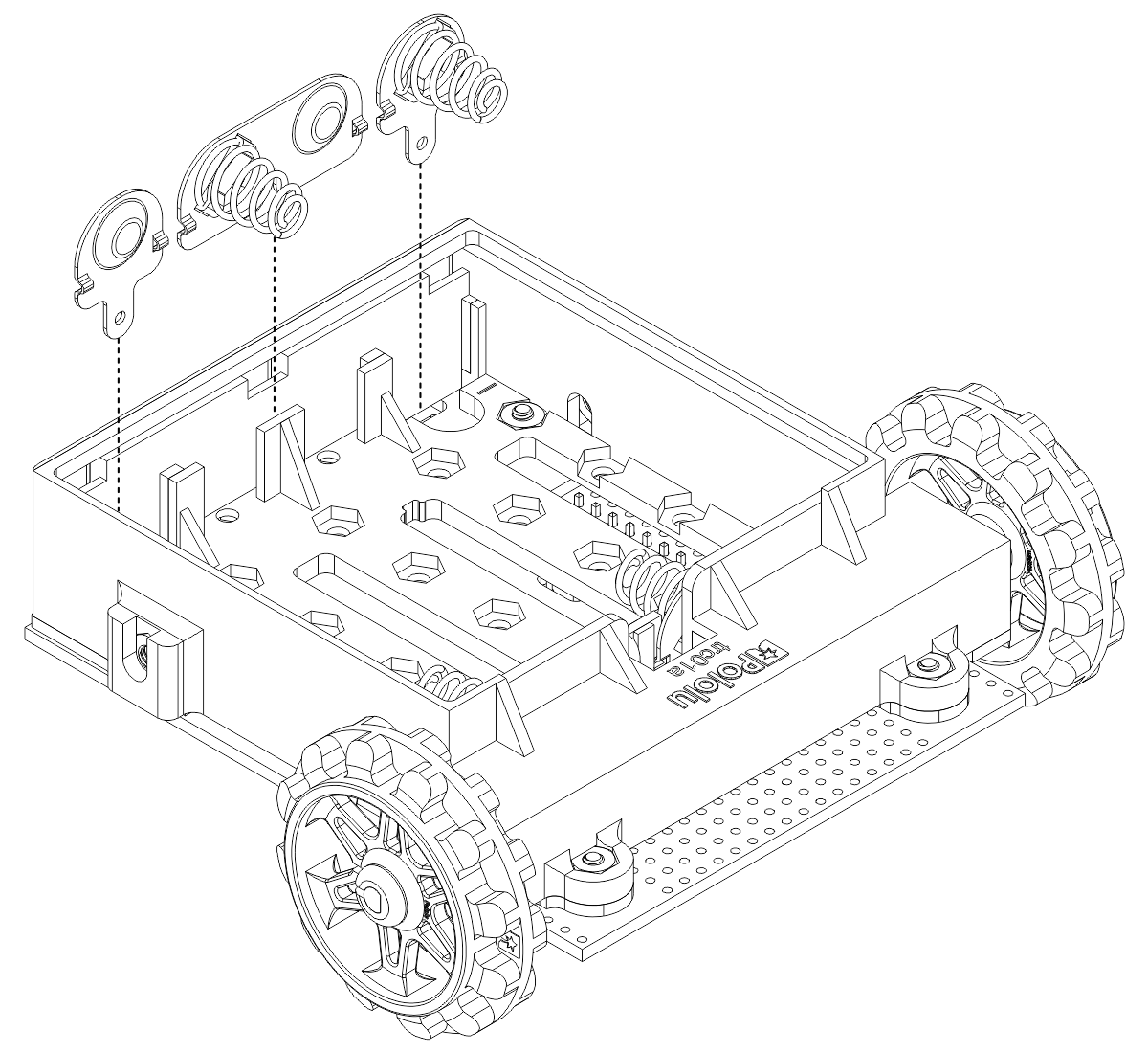
Battery contacts
16. Turn the chassis over and install the battery terminal contacts as shown in the picture below.
The three double-contact pieces should be firmly pressed into place until they are flush
with the interior surface of the battery compartment. The two individual contacts should be
inserted into the battery compartment so that their solder tabs protrude through the holes in
the top of the chassis; you might want to temporarily tape these two individual contacts in
place until they have been soldered to the shield as described in the next step, or you can
use a battery to temporarily hold them in place.
Pololu Zumo Shield for Arduino User’s Guide © 2001–2019 Pololu Corporation
2. Assembly Page 20 of 52
/


