Page is loading ...

www.barretteoutdoorliving.com
VERSARAIL ALUMINUM RAILING
INSTALLATION INSTRUCTIONS
73013137
73013138
73013139
73013140
Models
Owner's Manual
Version
1.0
34106596BOM V1 2/2012

Bracket
Balusters
Bottom Rail
Locking Strip
Base Mount
Base Mount
Base Trim
Center Support
Post
Post
Post Top
Post Top
Top Rail Profi le
Top Rail
*2 PERSON INSTALLATION RECOMMENDED
BEFORE YOU BEGIN:
It is the responsibility of the installer to meet and/or exceed all code and safety requirements, and to obtain all required building
permits. The deck and railing installer should determine and implement appropriate installation techniques for each installation.
Barrette Outdoor Living and its distributors shall not be held liable for improper or unsafe installations.
VERSARAIL ALUMINUM RAILING
INSTALLATION INSTRUCTIONS
6' Elite Railing Kits Include:
(1) Elite Top Rail Profi le
(2) Elite Rails
(2) Locking Strips
(1) Center Support
(1) Bracket Kit with Screws
(15) Square Balusters
8' Elite Railing Kits Include:
(1) Elite Top Rail Profi les
(2) Elite Rails
(2) Locking Strips
(2) Center Support
(1) Bracket Kit with Screws
(20) Square Balusters
Locking Strip

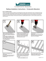
STEP 1.
STEP 2.
Closely follow post installation instructions.
Install brackets
a. With base trim installed on bottom of post, unroll
paper install template and tape to post, ensuring
the bottom of the template rests on the top of
the base trim. Predrill through marked locations on
installation template into aluminum post with a
5
⁄
5
⁄
5
32
⁄32⁄
"
drill bit. Do this for all marked locations for both
top and bottom brackets.
b. Screw bottom brackets into post using #8x
3
⁄
3
⁄
3
4
⁄4⁄
"
4" 4
screws.
c. Screw top brackets into post using #8x
3
⁄
3
⁄
3
4
⁄4⁄
" screws.
4" screws.4
*
Make sure base trim is installed
Template

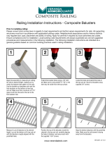
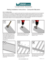
STEP 4.
Install support brace
a. One support brace is included with 6' railing kits. Measure equal distance from both ends of railing and install support brace in center of bottom rail
by snapping brace over the bottom rail.
b. Two support braces are included with 8' railing kits. Measure length of rail, divide by three, and then measure that distance from end of rail and
install support brace. Repeat this step from opposite side of the rail.
STEP 3.
Cut rails to length (top rail, bottom rail, hand rail profi le)
a. Place bottom rail across post opening leaving equivalent spacing from last baluster to post on each end.
b. Mark rail fl ush to post.
c. From marked line, mark additional parallel line
3
⁄
3
⁄
3
8
⁄8⁄
" from fi rst line, to allow for bracket clearance.
8
" from fi rst line, to allow for bracket clearance.
8
d. Align top rail and hand rail profi le with bottom rail, and cut same lengths with a saw (use fi ne tooth carbide blade).
d.
b&c.
a.

STEP 5.
Build out rail section
a. Place top and bottom rail on a smooth, fl at and clean surface. Then orient the top and bottom rails so that the "ridges" inside the rails are in the same
direction.
b. Thread all pickets through holes in rails being careful to have the "hole" in each picket going in the same direction, and proper direction.
c. Make sure pickets threaded through rails are about 2" above rail and in-line with each other.
d. Snap in bumps from plastic locking strip into holes of the pickets for both top and bottom rails. Make sure arrows on locking strips face rails.
e. If the rails were cut shorter in Step 2, then there will be some "extra" locking strip at the end of install. Use scissors to cut off excess (leave
approximately 2" of strip after the last engaged bump).
f. Push fi rst picket into bottom rail, followed by the second and third, until the last picket. Then repeat for top rail. The engagement between the rails,
pickets and locking strip is about 75% at this point.
g. Stand up rail section and fully lock the pickets into the rails. Place one foot on the top of the bottom rail, between second and third picket while at
the same time placing a hand under the bottom of the top rail between second and third picket. Push with foot and pull with hand until locking is
complete (You should hear a snap). Repeat this process for the middle and end of the panel. All the pickets should now be "locked" into the top and
bottom rails. (NOTE: If a snap is not heard or felt, use a rubber mallet to tap underneath of top rail to ensure a full connection.)
h. If the aluminum rail is to be installed with no vinyl topper line up hand rail profi le on top of the top rail. Press it down onto the top rail so it fi ts snug.
Slide bracket covers on ends of both top and bottom rails. (NOTE: Bracket covers are not used on the top rail when a rail topper is installed.)
i. If the aluminum rail is to be installed with a vinyl topper cut the vinyl topper the exact distance between posts. Fasten the vinyl topper as follows.
From underneath the aluminum rail profi le, drill two holes with a
5
⁄
5
⁄
5
8
⁄8⁄
" bit. Then, fi t the vinyl rail topper over the aluminum hand rail profi le. Once the
8" bit. Then, fi t the vinyl rail topper over the aluminum hand rail profi le. Once the 8
two parts are nested together, drive two #8x
3
⁄
3
⁄
3
8
⁄8⁄
" screws through the drilled holes of the aluminum profi le and into the mid-section of the vinyl topper.
8" screws through the drilled holes of the aluminum profi le and into the mid-section of the vinyl topper. 8
Repeat this for both ends, and middle of rail installation.
j.
Once vinyl rail topper is adhered to the aluminum profi le, align and press it down onto the top rail so it fi ts snug. Slide bracket covers onto bottom rail.
Ridges
a.
b&c.
b&c.
d.
d.
h.
h.
g.
g.
g.
j.
j.
i.

STEP 6.
Rails to Posts
a. Bring assembled rails between posts, elevated
above brackets
b. Once centered, slowly lower rail assembly carefully
to allow full engagement between section and
brackets in all four locations on posts. NOTE: The
top hand rail profi le should rest on the bottom of
the bracket that is screwed into post
c. Attach brackets to rails – Predrill two holes from
under the bottom of the top rail through rail.
Complete for each top rail bracket. Drive #8x2"
screws through drilled holes.
ANGLED INSTALLATIONS.
Follow previous steps above
• During Step 2, install the angle brackets at the
respective heights instead of line brackets
• During Step 3b, mark approximately 2" from end of
post to allow for angle bracket size. (This distance
may vary depending on individual installation.)
STEP 7.
Finishing Up
Push on pyramid post top to fasten on top of posts. NOTE: A rubber mallet may be needed to ensure tight connection.
www.barretteoutdoorliving.com
34106596BOM V1 2/2012
/