Page is loading ...

Owner's Manual
Version
1.0
Elite Rail
& Stair Rail
& Stair Rail
Assembly and Installation Instructions
Assembly and Installation Instructions
PLEASE READ OWNER'S MANUAL COMPLETELY
PLEASE READ OWNER'S MANUAL COMPLETELY
BEFORE ASSEMBLING YOUR RAIL.
ALL STATED SIZES ARE NOMINAL DIMENSIONS.
34106914BOM V1 7/13
73013042 / 73013043 / 73013044 / 73013048
73013049 / 73013050 / 73013051 / 73013052
73013053 / 73013054 / 73013055 / 73013056
73013069 / 73013071 / 73013073 / 73013079
73013080 / 73013081 / 73013085 / 73013086
73013087 / 73013088 / 73013095 / 73013096
73013282 / 73013306 / 73013307 / 73013308
73013314 / 73013315 / 73013316 / 73013317
73013318 / 73013319 / 73013320 / 73013321
73013335 / 73013345 / 73013346 / 73013347
73013348 / 73013349 / 73013841 / 73013842
73013843 / 73013844 / 73013845 / 73013846
73013847 / 73013848 / 73013849 / 73013850
73013851 / 73013852 / 73013853 / 73013854
73013855

2
6' Kits Include:
(1) Elite Rail Top Rail or Dual Rail
(1) Elite Rail Bottom Rail
(1) Elite Rail Chassis
(2) Elite Rail Baluster Spacers
(15) 1-1/8" Square Balusters
(30) Baluster Plugs
(1) Bracket Kit with Screws
(1) Support Brace
8' Kits Include:
(1) Elite Rail Top Rail or Dual Rail
(1) Elite Rail Bottom Rail
(1) Elite Rail Chassis
(2) Elite Rail Baluster Spacers
(20) 1-1/8" Square Balusters
(40) Baluster Plugs
(1) Bracket Kit with Screws
(2) Support Braces
10' Kits Include:
(1) Elite Rail Top Rail or Dual Rail
(1) Elite Rail Bottom Rail
(1) Elite Rail Chassis
(2) Elite Rail Baluster Spacers
(25) 1-1/8" Square Balusters
(50) Baluster Plugs
(1) Bracket Kit with Screws
(2) Support Braces
Plug
Bracket
Baluster
Baluster
Spacer
Top Rail
Base Trim
Center Support
Brace
Bottom
Rail
Post
Sleeve
Post Top
Baluster
Spacer
Chassis
Center Support
Thank you for choosing the Barrette Outdoor Living Railing.
Please read the instructions completely before assembling
your rail. Retain manual and your dated sales slip for future
reference and warranty claims.
Before You Begin…
Make sure your project meets local building codes before
beginning installation.
ATTENTION:
Before you assemble the rail:
PLEASE TAKE A COMPLETE INVENTORY OF ALL PARTS USING THE KIT CONTENTS.
DO NOT ATTEMPT TO ASSEMBLE THE RAIL IF PARTS ARE MISSING OR DAMAGED.
Please do not return the product to the store, for assistance or replacement parts call:
1-800-336-2383
Material Checklist:
Tape Measure
Level
Hacksaw or Chopsaw
Rubber Mallet
Drill
Rail Assembly:
Rail Installation

3
1
1
2
2
TIP: Precision cuts required to ensure optimum tight installation and fi t.
Use chopsaw with thin carbide tip blade to ensure smooth cuts.
Pay particularly close attention to angle cuts to ensure tight fi t.
1.1: Closely follow post install kit instructions (or sleeve existing wood 4x4) - Instructions
included in Post Install Kit (sold separately).
1.2: Trim Post sleeve to desired length.
(39" is recommended for a 36" fi nished rail height. 45" is recommended for a
42" fi nished rail height)
(NOTE: If installing railing with a deck board as a top rail and “over the post”, see note
in Step 7 fi rst!)
(NOTE: If installing Elite low voltage lighting, refer to Elite L.V. Lighting installation guide
for post heights.)
1.3: Slide post sleeve and base trim over wood 4 x 4 or already installed post
install kit (See separate post install kit instructions).
2.1: Measure the distance at the bottom of the post sleeves between already installed posts.
2.2: As long as posts are plumb, top rail length will equal bottom rail.
2.3: Cut top and bottom rails to length. When cutting top rail be sure to begin cut through top of top rail for best fi nish.
2.4 Place baluster spacer in top of bottom rail, which was cut to proper length in Step 2.3. Align allowing for equal distance of end holes to end of rail. Mark baluster spacer on each
end with a pencil. As long as posts are plumb top rail baluster spacer will equal bottom rail baluster spacer. Cut baluster spacers one at a time. Be sure to cut slowly with a fi ne
tooth blade, positioning the "legs" downward.
2.5: Cut chassis to a length of 4" less than the distance between posts. Be careful when handling the cut chassis.
2.6: For angled installations, see Step 7.
Install Post Sleeves and Base Trim
Cut Your Rails to Length

4
3
3
3.1: Install lower rail brackets. Position the provided bracket install template on the top of the installed post base
trim. Use template to align the bottom brackets to the center of the post sleeve, making sure "THIS SIDE UP"
on bracket faces up. Pre-drill bracket holes with 1/8" drill bit and attach bracket with #10 x 2-1/2"
supplied screws.
3.2: Install Center Support Brace
A. For 6' sections one support brace is included
• Measure equal distance from both ends of bottom railing
and install support brace in center of bottom rail with
supplied screws (two #10 x 3/4"). (Pre-drill with 1/8" drill bit.)
B. For 8' and 10' sections two support braces are included
• Measure length of bottom rail and divide by three - then
measure that distance from each end of rail and install
support braces with supplied screws (two #10 x 3/4").
(Pre-drill with 1/8" drill bit.)
3.3: Install the bottom rail to the previously attached brackets. Slide bottom rail on top of brackets. Approximately 1-3/4" (Not more than 3") from end of post, pre-drill through rail
and bracket with 1/8" drill bit. Drive the provided (#10 x 1") screw through the top of the bottom rail into brackets.
3.4: Place baluster spacer into the top of the bottom rail.
3.5: Install baluster plugs into the holes of the bottom rail baluster spacer. Push each plug
through the routed hole until you hear a snap. Repeat until every hole is fi lled with a
baluster plug.
Prepare the Bottom Rail
4
4
4.1: Slide balusters over the previously installed baluster plugs. Each
baluster should be straight up, perpendicular to the bottom rail, and
parallel to the posts.
Installing the balusters

5
5
5
5.1: Plug in top brackets to chassis with "This Side Up" facing up to the top.
5.2: Attach the bracket to the chassis with a supplied #8 x 5/8" self tapping
screw in groove in chassis. Repeat on opposite side. (NOTE: For 10' rail
kits, chassis will be made of aluminum and should be pre-drilled with
1/8" drill bit.)
5.3: Turn chassis upside down and lay baluster spacer on top of chassis.
Make sure the baluster spacer completely covers the chassis and
brackets without extending beyond ends of brackets.
5.4: Install baluster plugs through baluster spacer into the chassis until you
hear a snap.
5.5: Carry assembled top rail chassis and plugs over to rail section and slide
baluster plugs into the top of the previously installed balusters. Align
plugs partially into each baluster. After all are engaged, fi rmly push
down to ensure balusters fully engage the baluster plugs and the top
baluster spacer becomes tight to the chassis.
5.7: Pre-drill with a 13/64" drill bit from the top
of the installed chassis down all the way
through baluster spacer cover. Start on
one side of fi rst bracket in corner nooks as
indicated. For 6' rails, install two screws
per bracket and two additional screws
at midway point between brackets and
chassis. Be sure to drill directly through the
scored lines on the top of chasses. For 8'
rails, install two screws per bracket, and
remaining four screws equally spaced.
5.6: Using supplied #10 x 2-1/2" screws, attach top brackets to center of
post. (NOTE: Be sure to push down on top of chassis while screwing
into post to make the fi t "snug")
Prepare the Top Rail
6' Rail
8' Rail
Drill on scored lines
Evenly space the screws

6
6
6
7
7
6.1: Slide top rail over the top of the assembled “chassis” fi tting snug to posts.
7.1: Use wood 2x4 as a template prior to cutting Elite railing on angles.
7.2: Place 2x4 on top of posts in which angle cut is needed. Mark from
underneath and cut angle.
7.3: Place wood piece between posts to ensure tight fi t.
7.4: Cut the top and bottom rails at same length/angle as wood piece.
7.5: Cut the top and bottom rail brackets (4) at same angle as rail. Do this
by temporarily connecting brackets to chassis. (Chassis provides a safe
handling of bracket so as not to have hands or fi ngers near saw blade
while cutting). Remove brackets from Chassis.
7.6: Install bottom rail brackets using template to locate proper height of
brackets (see Step 3.1).
7.7: Place baluster spacer in the top of the previously cut bottom rail. Align
allowing for equal distance of end holes to end of rail. Mark baluster
spacer on each end with a pencil.
7.8: Cut bottom spacer to marked length and angle, being sure to cut slowly
with a fi ne tooth blade making sure "legs" are facing downward.
7.9: Cut top spacer to same length and angle as bottom spacer, in same
orientation.
7.10: Install bottom rail to previously attached brackets (see Step 7.6).
7.11: Place baluster spacer into bottom rail.
7.12: Install plugs and balusters
(Steps 3.5, 4.1)
7.13: a.) Attach cut bracket to end of Chassis (with screws) on one end only.
b.) Then, place Chassis and secured bracket into the top rail, making sure
the cut bracket and cut rail are fl ush (see Figure B.)
c.) Next, plug in second bracket to opposite end of Chassis
(do not screw in yet). Note: the bracket will extend beyond the end of
the rail.
d.) Measure distance from end of cut rail to end of extended cut bracket
(as shown in Figure D). Make sure your tape measure runs parallel to
the rail/chassis to allow you to get the most accurate measurement.
e.) Remove bracket (the one that was not screwed in). Then, cut Chassis
down by distance measured in Step 7.13d.
(Note: assembled length of Chassis + Brackets = assembled length
of the rail.)
Go To Step 5 to install Top Rail
6.2: Through the holes in the top rail baluster spacer made in Step 5.7, screw the
provided #10 x 2" screws through the baluster spacer and chassis into the top
rail to connect the assembly.
Installing the balusters
Installing Elite Railing on Angles
B.
D.
D.

7
8
8
Note: Make sure posts are at same height as rail installation (with a good, tight installation, post and post sleeve to be cut to 35 13/16" high)
8.1: Follow instructions from Steps 2-3-4-5.
8.2: Place deck board (sold separately) over the top rail. Attach with board manufacturer recommended 2" screws into center of rail, through board, ensuring
screws engage chassis.
Installing the Deck Board in “Over the Top” Format
Deck Board
Top
Rail

8
Top Rail
Baluster
Plug
Stair
Stair
Bracket
Base Trim
Baluster Spacer
Bottom Rail
Stair Post
Stair Post
Sleeve
Post Top
Baluster Spacer
Stair
Bracket
Chassis
6' Stair Kits Include:
6' Stair Kits Include:
(1) Elite Rail Top Rail
(1) Elite Rail Top Rail
(1) Elite Rail Bottom Rail
(1) Elite Rail Bottom Rail
(1) Elite Rail Chassis
(1) Elite Rail Chassis
(2) Elite Rail Baluster Spacers
(2) Elite Rail Baluster Spacers
(14) 1-1/8" Square Balusters
(14) 1-1/8" Square Balusters
(30) Baluster Plugs
(30) Baluster Plugs
(1) Stair Bracket Kit with Screws
(1) Stair Bracket Kit with Screws
(1) Screw pack
(1) Screw pack
8' Stair Kits Include:
8' Stair Kits Include:
(1) Elite Rail Top Rail
(1) Elite Rail Top Rail
(1) Elite Rail Bottom Rail
(1) Elite Rail Bottom Rail
(1) Elite Rail Chassis
(1) Elite Rail Chassis
(2) Elite Rail Baluster Spacers
(2) Elite Rail Baluster Spacers
(19) 1-1/8" Square Balusters
(19) 1-1/8" Square Balusters
(40) Baluster Plugs
(40) Baluster Plugs
(1) Stair Bracket Kit with Screws
(1) Stair Bracket Kit with Screws
(1) Screw pack
(1) Screw pack
ATTENTION:
Before you assemble the rail:
PLEASE TAKE A COMPLETE INVENTORY OF ALL PARTS USING THE KIT CONTENTS.
DO NOT ATTEMPT TO ASSEMBLE THE RAIL IF PARTS ARE MISSING OR DAMAGED.
Please do not return the product to the store, for assistance or replacement parts call:
1-800-336-2383
Material Checklist:
Tape Measure
Level
Hacksaw or Chopsaw
Rubber Mallet
Drill
Drill bits
#2 square drive bit
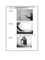
Stair Rail Assembly:
Stair Rail Installation
Thank you for choosing the Barrette Outdoor Living Railing.
Please read the instructions completely before assembling
your rail. Retain manual and your dated sales slip for future
reference and warranty claims.
Before You Begin…
Make sure your project meets local building codes before
beginning installation.

9
1
1
2
2
1.1: Trim Post sleeve to desired length. In most cases, the post and post
sleeve at the bottom of the stairs will need to be longer than posts
on the deck, to accomodate stair angles. (41" bottom stair post is
recommended for a 36" fi nished rail height. 47" bottom stair post is
recommended for a 42" fi nished rail height)
(NOTE: If installing Elite railing with a deck board as a top rail and
“over the post”, see note in Step 6 fi rst!)
1.2: Make sure the top and bottom posts for stairs are installed so the
base trims are installed at the nose of each tread.
1.3: Check to ensure the posts are plumb.
1.4: Slide post sleeve and base trim over wood 4 x 4 or already installed
post install kit.
(See separate post install kit instructions)
2.1: Place a temporary 5/4" deck board on top of stair noses for proper
spacing underneath rails.
2.3: Mark the posts directly under the bottom rail, where the rail
intersects both posts. From that mark, go up 1/2" and draw line
across post. This will be your locator for bottom bracket placement.
2.2: Set bottom rail baluster spacer inside bottom rail on top of temporary spacer board. Align
rail and baluster spacer on posts until there is equal distance from post to fi rst baluster hole
on top and bottom of stairs; clamp to posts.
Install Post Sleeves and Base Trim
Prepare The Bottom Rail
TIP: Building codes are specifi c as to angles, steepness, and dimensions of stair installations.
Typical stair angles are usually 32 degrees (7" rise, and 11" run). Check with your local building code offi cial as you plan your
stair layout. Pay particularly close attention to angle cuts to ensure a tight fi t.
Elite stair rail kits work with a stair slope from 26 degrees - 38 degrees; optimal at 32 degrees.
1/2"
2.4: Mark angled line on bottom rail assembly at intersection of rail and posts.
2.5: Remove rail and baluster spacer from temporary spacer board and posts and cut at
marked angle.
2.6: Remove temporary spacer board.
2.7: If angle is not 32 degrees, cut bottom stair brackets to same angle as rail and spacer.
2.8: Install bottom bracket at height found in Step 2.3 with #10x2" screws. The bottom of the
bracket should align directly on the upper line marked on the post.
2.9: Remove previously cut bottom baluster spacer from bottom rail.

10
2
2
3
3
4
4
2.10: Slide bottom rail over installed brackets, fi tting rail snug to posts.
Approximately 1/2" from end of post, pre-drill through rail and bracket
with 1/8" drill bit. Drive the provided #10 x 1" screw through the top of the
bottom rail into bottom bracket.
3.1: For 1-1/8" square balusters:
Cut balusters with miter saw, top and bottom, to same angle as the
bottom rail cut.
3.2: For 3/4" round aluminum stair balusters: the top & bottom ends of the
balusters are already cut to a 32 degree angle. For severe angles trim the
bottom of your aluminum stair baluster to appropriate angle. (Top end will
be hidden in top rail)
3.3: Slide balusters over the previously installed baluster plugs.
Each baluster should be straight up, parallel to the posts and fl ush to the
bottom rail.
4.1: Measure distance between top of installed posts. As long as posts are
plumb, the distance will equal the distance at the bottom. This will be the
top rail distance.
4.2: To determine chassis length, insert lower bracket into one end of chassis.
Then place chassis on stair treads with the lower bracket against the
lower post. Using the upper bracket as template, mark the chassis where it
needs to be cut to fi t between the posts. Cut chassis to length.
NOTE: Do not cut chassis at an angle
4.3: Clamp top rail and baluster spacer along the sides of the posts, so that the
distance between the post to the fi rst routed hole is equal on both ends
Mark angled line on top rail assembly at intersection.
4.4: Cut top rail and baluster spacer to proper length and angle with miter saw.
4.5: Plug in top stair brackets to chassis.
2.11: Re-install bottom baluster spacer
2.12: Install baluster plugs into the holes of the bottom baluster spacer. Push
each plug through the routed hole until you hear a snap, repeat until every
hole is fi lled with a plug.
(Continued From Previous Page)
Installing The Balusters
Prepare The Top Rail
TIP: When miter cutting balusters make sure to
start cut at top edge of baluster to maximize length
and ensure consistent cuts between balusters.
TIP: Ensure proper fi t by cutting a test piece of wood to
the previously determined length and angle to fi t into the
opening between the posts.

11
4
4
4.6: Attach the bracket to the chassis with supplied #8 x 5/8" self
tapping screw in groove in chassis. Repeat on opposite side.
4.7: If angle is not 32 degrees cut bracket to desired angle.
4.8: Remove baluster spacer from top rail.
4.9: Turn chassis upside down and lay baluster spacer on top of
chassis.
Make sure the baluster spacer completely covers the chassis
and brackets
without extending beyond ends of brackets.
4.10: Install baluster plugs through spacer cover into the
chassis until you hear a snap.
4.11: Carry assembled top rail chassis and plugs over to rail
section and slide baluster plugs into the previously
installed balusters. Align plugs partially into each
baluster. After all are engaged,
fi rmly push down to ensure balusters fully engage the
baluster plugs and the top baluster spacer becomes
tight to the aluminum chassis.
4.12: Using supplied #10 x 2" screws, attach top brackets to
center of post.
4.13: Pre-drill with a 13/64" drill bit from the top of the
installed chassis down all the way through baluster
spacer cover. Drill holes on both sides of chassis on
the scored lines. Drill fi rst two holes between the fi rst
and second baluster, then, drill the remaining holes
evenly across the length of the chassis.
(Continued From Previous Page)
Drill between
fi rst and second
baluster
Drill on scored lines

12
5
5
6
6
5.1: Slide previously cut top rail over the top of the assembled chassis, fi tting
snug to posts.
(Make sure bottom stair post is at same angle as stair rail installation.
Bottom stair post height will vary depending on angle of stair installation)
6.1: Follow instructions from step 2.
6.2: Follow instructions from step 3.
6.3: Follow instructions from step 4.
6.4: Follow instructions from step 5.
6.5: Place deck board (sold separately) over the top rail. Attach with board
manufacturer recommended 2" screws into center of rail through board,
ensuring screws engage chassis.
5.2: Through the holes in the top rail baluster spacer made in step 4.13, screw the provided
#10 x 2" screws through the baluster spacer and chassis into the top rail to connect the
assembly.
Installing The Top Rail
Installing the Deck Board "Over the Top" Format

13
7
7
Add a fi nal touch by attaching post tops to the posts.
Finishing Touches

34106914BOM V1 7/13
© 2013 Barrette Outdoor Living • 7830 Freeway Circle • Middleburg Heights, Ohio • 44130
http://www.barretteoutdoorliving.com • 1-800-336-2383
Transferable Limited Lifetime Warranty
What is covered: Barrette Outdoor Living warrants vinyl and aluminum products to include; vinyl and aluminum fence, vinyl and
aluminum railing and plastic lattice against defects or workmanship for as long as you own your home. Barrette Outdoor Living
will at its option replace the product in question with new product of the same or equivalent value at no charge. Barrette Outdoor
Living warrants these products against peeling, fl aking, splintering, corrosion, rusting or abnormal discoloration under normal
use and service per ASTMD 2244. This warranty extends to the original purchaser or transferee as specifi ed herein on the
products noted above. Separate and distinct warranties for hardware and other products are not covered under this warranty.
What this warranty does not cover: This limited warranty does not cover damage resulting from accident, unreasonable use,
neglect, alteration, improper service, improper installation, acts of God or any other causes not arising out of defects in materials
or workmanship. Additionally, this warranty does not cover costs of installation, removal, reinstallation or surface mold and
mildew created by excessive environmental conditions. Any service or repair provided outside the scope of this limited warranty
shall be at Barrette Outdoor Living’s rate and terms then in effect.
What do we do to correct the problems? Should your Barrette Outdoor Living product prove defective under warranty, reference
the website or call the phone number listed below. Your problem will be assigned a tracking number and an authorized Barrette
Outdoor Living representative will contact you to arrange a convenient time to schedule an onsite inspection, or request pictures,
if need be. If after inspection product is deemed to be manufacturer defect we will make arrangements to rectify the issue. You
must have proof of your purchase in order for the problem to be corrected.
Transferee Coverage: Warranty coverage will be extended to one transferee on the above listed products with the following
limitations. Transferee must obtain an original or copy of the initial sales receipt (with proof of date) from the previous owner(s).
Additionally, if fence is purchased from a builder or installer, documentation must be supplied that names the product installed
on property and date of transfer.
THIS WARRANTY IS IN LIEU OF ALL CONDITIONS OR WARRANTIES, EXPRESS, OR IMPLIED INCLUDING BUT NOT LIMITED TO
ANY IMPLIED CONDITIONS OR WARRANTIES OR MERCHANTABILITY OR FITNESS FOR A PARTICULAR PURPOSE ON THE PART OF
Barrette OR ITS LICENSORS, SOME STATES DO NOT ALLOW THE EXCLUSIONS OF IMPLIED WARRANTIES OR LIMITATIONS OF
HOW LONG AN IMPLIED WARRANTY LASTS, SO THE ABOVE LIMITATIONS MAY NOT APPLY TO YOU. IF THE PRODUCT IS DEFECTIVE
PER THE ABOVE COVERAGES, YOUR SOLE AND EXCLUSIVE REMEDY SHALL BE REPAIR OR REPLACEMENT AS PROVIDED ABOVE.
BARRETTE AND ITS LICENSORS SHALL NOT BE LIABLE FOR ANY DAMAGES, LOSS OF USE, LOSS OF PROFITS OR INTERRUPTION
OF BUSINESS WHETHER SUCH ALLEGED DAMAGES ARE BASED IN WARRANTY, TORT, CONTRACT, OR INDEMNITY. SOME STATES
DO NOT ALLOW THE EXCLUSION OF LIMITATIONS OF INCIDENTAL OR CONSEQUENTIAL DAMAGES, SO THE ABOVE LIMITATIONS
MAY NOT APPLY TO YOU. This warranty is valid only in the United States and Canada.
Refer to www.BarretteOutdoorLiving.com for specifi c details about warranty limitations.
1-800-336-2383
To register your product, please visit: www.barretteoutdoorliving.com/product-registration
/