Page is loading ...

73013137 / 73017821
73013138 / 73017822
73013139 / 73017823
73013140 / 73017824
Models
Owner's Manual
Version
3.2
Aluminum Railing
PLEASE READ OWNER'S MANUAL COMPLETELY
A
PLEASE READ OWNER'S MANUAL COMPLETELY
A
ssembly and Installation Instructions
PLEASE READ OWNER'S MANUAL COMPLETELY
ssembly and Installation Instructions
BEFORE ASSEMBLING YOUR RAILING KIT.
Elite Installation Instructions
34109832BOM V3.2 4/2013

2
Bracket
Balusters
Bottom Rail
Locking Strip
Base Mount
Base Trim
Center Support
Post
Post
Post Top
Top Rail Profi le
Top Rail
Locking Strip
Locking Strip
*2 PERSON INSTALLATION RECOMMENDED
BEFORE YOU BEGIN:
IMPORTANT:
It is the responsibility of the installer to meet and/or exceed all code and safety requirements, and to obtain all required building
permits. The deck and railing installer should determine and implement appropriate installation techniques for each installation.
Barrette and its distributors shall not be held liable for improper or unsafe installations.
This instruction manual contains 4 types of installation options:
• Straight rail installation
• Straight rail with vinyl topper
• Angled rail installation
• Angled rail with vinyl topper
6' Elite Railing Kits Include:
(1) Elite Top Rail Profi le
(2) Elite Rails
(2) Locking Strips
(2) Center Support
(1) Bracket Kit with Screws
(15) Square Balusters
8' Elite Railing Kits Include:
(1) Elite Top Rail Profi les
(2) Elite Rails
(2) Locking Strips
(4) Center Support
(1) Bracket Kit with Screws
(20) Square Balusters

3
STRAIGHT RAIL INSTALLATION
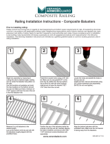
Closely follow post installation instructions.
*
Make sure base trim is installed
Template
1
1
2
2
Install brackets
a. With base trim installed on bottom of post, unroll
a. With base trim installed on bottom of post, unroll
paper install template and tape to post, ensuring
the bottom of the template rests on the top of the
the bottom of the template rests on the top of the
base trim. Predrill through all marked locations on
installation template "L" (not "A") into aluminum post
installation template "L" (not "A") into aluminum post
with a
9
⁄
64
" drill bit. Do this for all marked locations
" drill bit. Do this for all marked locations
for both top and bottom brackets.
b. Screw bottom brackets into post using #8x1
1
⁄
2
⁄2⁄
" Pan
2" Pan 2
Head screws (2 per bracket).
c. Screw top brackets into post using #8x1
1
⁄
2
⁄2⁄
" Pan Head
" Pan Head
2" Pan Head 2
screws (4 per bracket).

4
Build out rail section
a. Place top and bottom rail on a smooth, fl at and clean surface. Then, orient
the top and bottom rails so that the ridges inside the rails are oriented in
the same direction. NOTE: There are two (2) ridges on both sides, but of
the top and bottom rails so that the ridges inside the rails are oriented in
the same direction. NOTE: There are two (2) ridges on both sides, but of
the top and bottom rails so that the ridges inside the rails are oriented in
different sizes.
the same direction. NOTE: There are two (2) ridges on both sides, but of
different sizes.
the same direction. NOTE: There are two (2) ridges on both sides, but of
b. Thread all balusters through the holes in rails being careful to have the
"hole" in each baluster going in the same direction (and facing the two small
b. Thread all balusters through the holes in rails being careful to have the
"hole" in each baluster going in the same direction (and facing the two small
b. Thread all balusters through the holes in rails being careful to have the
ridges/score line side)
c. Make sure balusters threaded through rails are about 2" above rail and in-
line with each other.
d. Snap in bumps from plastic locking strip into holes of the balusters for both
top and bottom rails. Make sure arrows on locking strips face rails.
d. Snap in bumps from plastic locking strip into holes of the balusters for both
top and bottom rails. Make sure arrows on locking strips face rails.
d. Snap in bumps from plastic locking strip into holes of the balusters for both
e. If the rails were cut shorter in Step 3, then there will be some "extra" locking
strip at the end of install. Use scissors to cut
e. If the rails were cut shorter in Step 3, then there will be some "extra" locking
strip at the end of install. Use scissors to cut
e. If the rails were cut shorter in Step 3, then there will be some "extra" locking
off excess (leave approximately 2" of strip
strip at the end of install. Use scissors to cut
off excess (leave approximately 2" of strip
strip at the end of install. Use scissors to cut
after the last engaged bump).
off excess (leave approximately 2" of strip
after the last engaged bump).
off excess (leave approximately 2" of strip
f. Push fi rst baluster into bottom rail, followed
by the second and third, until the last
baluster. Then repeat for top rail. The
by the second and third, until the last
baluster. Then repeat for top rail. The
by the second and third, until the last
engagement between the rails, balusters and
locking strip is about 75% at this point.
Cut rails to length (top rail, bottom rail, top rail profi le).
a. Place bottom rail across post opening leaving equivalent spacing from last baluster to post on each end. Make sure there is even spacing from
baluster hole to post.
b. Mark rail fl ush to post.
c. From marked line, mark additional parallel line
3
⁄
3
⁄
3
8
⁄8⁄
" from fi rst line, to allow for bracket clearance.
8
" from fi rst line, to allow for bracket clearance.
8
d. Align top rail and top rail profi le with bottom rail and mark before cutting to size. Then cut same lengths with a saw (use fi ne tooth carbide blade).
b&c.
a.
STRAIGHT RAIL INSTALLATION
STRAIGHT RAIL INSTALLATION
3
3
4
4
d.
Top Rail Opening Facing Up
Top Rail Opening Facing Up
Bottom Rail Opening Facing Down
Bottom Rail Opening Facing Down
Two
Large
Ridges
Two
Large
Ridges
Two
Small
Ridges
Two
Small
Ridges
Two
a.
b&c.
b&c.
d.
d.
Two small ridges/
Score line side
Two large
ridges side
2"
Arrows on opposite side, pointing down
Top view of rail
"score" inside

5
h.
h.
g.
g.
g.
i.
STRAIGHT RAIL INSTALLATION
Rails to Posts
a. Bring assembled rails between posts, elevated above brackets
assembled in Step 2.
b. Once centered, slowly lower rail assembly carefully to allow full
engagement between section and brackets in all four locations on
posts. NOTE: The top top rail profi le should rest on the bottom of the
bracket that is screwed into post
c. Attach brackets to rails – Predrill two holes from under the bottom of
the top rail through rail. Complete for each top rail bracket. Drive
#8x1
1
⁄
2
⁄2⁄
" Pan Head screws (2 per bracket) through drilled holes.
2" Pan Head screws (2 per bracket) through drilled holes.2
Install support brace
a. Two support braces are included with 6' railing kits. For code purposes, only one is required for installations in the U.S., while all three
are required in Canada. Spread out the braces proportionately (place center one in middle).
b. Four support braces are included with 8' railing kits. For code purposes, only two are needed for installations in the U.S., while all four
are required in Canada. Spread out the braces proportionately.
5
5
6
6
Finishing Up
If using a pyramid post top, push to fasten on top of
posts. NOTE: A rubber mallet may be needed to
ensure tight connection.
7
7
g. Stand up rail section and fully lock the balusters into the rails. Place one foot on the top of the bottom rail, between second and third baluster while
at the same time placing a hand under the bottom of the top rail between second and third baluster. Push with foot and pull with hand until locking is
g. Stand up rail section and fully lock the balusters into the rails. Place one foot on the top of the bottom rail, between second and third baluster while
complete (You should hear a snap). Repeat this process for the middle and end of the panel. All the balusters should now be "locked" into the top and
at the same time placing a hand under the bottom of the top rail between second and third baluster. Push with foot and pull with hand until locking is
bottom rails. (NOTE: If a snap is not heard or felt, use a rubber mallet to tap underneath of top rail to ensure
complete (You should hear a snap). Repeat this process for the middle and end of the panel. All the balusters should now be "locked" into the top and
bottom rails. (NOTE: If a snap is not heard or felt, use a rubber mallet to tap underneath of top rail to ensure
complete (You should hear a snap). Repeat this process for the middle and end of the panel. All the balusters should now be "locked" into the top and
a full connection.)
bottom rails. (NOTE: If a snap is not heard or felt, use a rubber mallet to tap underneath of top rail to ensure
a full connection.)
bottom rails. (NOTE: If a snap is not heard or felt, use a rubber mallet to tap underneath of top rail to ensure
h. Line up top rail profi le on top of the top rail. Press it down onto the top rail so it fi ts snug.
i. Slide bracket covers on ends of both top and bottom rails.

6
STRAIGHT RAIL WITH VINYL TOPPER AND POST INSTALLATION
STRAIGHT RAIL WITH VINYL TOPPER AND POST INSTALLATION
Install brackets
a. With base trim installed on bottom of vinyl post,
unroll paper install template and tape to post,
ensuring the bottom of the template rests on the
top of the base trim as specifi ed. Predrill through all
marked locations on installation template "L" (not
"A") into vinyl post with a
9
⁄
64
" drill bit. Do this for all
marked locations for both top and bottom brackets.
b. Screw bottom brackets into post using #8x1
1
⁄
2
" Pan
Head screws (2 per bracket).
c. Screw top brackets into post using #8x1
1
⁄
2
" Pan Head
screws (4 per bracket).
*
Make sure base trim is installed
Template
Closely follow post installation instructions for vinyl posts.
1
1
2
2

7
STRAIGHT RAIL WITH VINYL TOPPER AND POST INSTALLATION
Cut rails to length (top rail, bottom rail, top rail profi le).
a. Place bottom rail across post opening leaving equivalent spacing from last baluster to post on each end. Make sure there is even spacing from
baluster hole to post.
b. Mark rail fl ush to post.
c. From marked line, mark additional parallel line
3
⁄
3
⁄
3
8
⁄8⁄
" from fi rst line, to allow for bracket clearance.
8
" from fi rst line, to allow for bracket clearance.
8
d. Align top rail and top rail profi le with bottom rail and mark before cutting to size. Then cut same lengths with a saw (use fi ne tooth carbide blade).
d.
b&c.
a.
3
3
4
4
Build out rail section
a. Place top and bottom rail on a smooth, fl at and clean surface. Then, orient
the top and bottom rails so that the ridges inside the rails are oriented in
the same direction. NOTE: There are two (2) ridges on both sides, but of
the top and bottom rails so that the ridges inside the rails are oriented in
the same direction. NOTE: There are two (2) ridges on both sides, but of
the top and bottom rails so that the ridges inside the rails are oriented in
different sizes.
the same direction. NOTE: There are two (2) ridges on both sides, but of
different sizes.
the same direction. NOTE: There are two (2) ridges on both sides, but of
b. Thread all balusters through the holes in rails being careful to have the
"hole" in each baluster going in the same direction (and facing the two small
b. Thread all balusters through the holes in rails being careful to have the
"hole" in each baluster going in the same direction (and facing the two small
b. Thread all balusters through the holes in rails being careful to have the
ridge/score line side)
c. Make sure balusters threaded through rails are about 2" above rail and in-
line with each other.
d. Snap in bumps from plastic locking strip into holes of the balusters for both
top and bottom rails. Make sure arrows on locking strips face rails.
d. Snap in bumps from plastic locking strip into holes of the balusters for both
top and bottom rails. Make sure arrows on locking strips face rails.
d. Snap in bumps from plastic locking strip into holes of the balusters for both
e. If the rails were cut shorter in Step 3, then
there will be some "extra" locking strip at the
end of install. Use scissors to cut off excess
there will be some "extra" locking strip at the
end of install. Use scissors to cut off excess
there will be some "extra" locking strip at the
(leave approximately 2" of strip after the last
engaged bump).
(leave approximately 2" of strip after the last
engaged bump).
(leave approximately 2" of strip after the last
f. Push fi rst baluster into bottom rail, followed
by the second and third, until the last baluster.
Then repeat for top rail. The engagement
by the second and third, until the last baluster.
Then repeat for top rail. The engagement
by the second and third, until the last baluster.
between the rails, balusters and locking strip
is about 75% at this point.
Top Rail Opening Facing Up
Top Rail Opening Facing Up
Bottom Rail Opening Facing Down
Bottom Rail Opening Facing Down
Two
Large
Ridges
Two
Large
Ridges
Two
Small
Ridges
Two
Small
Ridges
Two
a.
b&c.
b&c.
d.
d.
Two small ridges/
Score line side
Two large
ridges side
2"
Arrows on opposite side, pointing down
Top view of rail
"score" inside

8
STRAIGHT RAIL WITH VINYL TOPPER AND POST INSTALLATION
Install Toppers
a. Cut the vinyl topper the exact distance between posts. Fasten then vinyl topper as follows:
b. From underneath the aluminum rail Top Rail Profi le, drill two holes with a 3/16" drill bit.
c. Then fi t the vinyl topper over the aluminum top rail profi le.
d. Once the two parts are nested together, drive two #10 x 1" screws through the drilled holes of the aluminum profi le and into the mid-section of the vinyl
topper. Repeat this for both ends and middle of rail installation (6 screws needed per topper installed).
d. Once the two parts are nested together, drive two #10 x 1" screws through the drilled holes of the aluminum profi le and into the mid-section of the vinyl
topper. Repeat this for both ends and middle of rail installation (6 screws needed per topper installed).
d. Once the two parts are nested together, drive two #10 x 1" screws through the drilled holes of the aluminum profi le and into the mid-section of the vinyl
e. Once vinyl topper is secure to the aluminum profi le, align and press it down onto the top rail so its snug.
b.
b.
d.
d.
e.
6
6
g.
g.
g.
h.
h.
g. Stand up rail section and fully lock the balusters into the rails. Place
one foot on the top of the bottom rail, between second and third
g. Stand up rail section and fully lock the balusters into the rails. Place
one foot on the top of the bottom rail, between second and third
g. Stand up rail section and fully lock the balusters into the rails. Place
baluster while at the same time placing a hand under the bottom
of the top rail between second and third baluster. Push with foot
baluster while at the same time placing a hand under the bottom
of the top rail between second and third baluster. Push with foot
baluster while at the same time placing a hand under the bottom
and pull with hand until locking is complete (You should hear a
snap). Repeat this process for the middle and end of the panel.
and pull with hand until locking is complete (You should hear a
snap). Repeat this process for the middle and end of the panel.
and pull with hand until locking is complete (You should hear a
All the balusters should now be "locked" into the top and bottom
rails. (NOTE: If a snap is not heard or felt, use a rubber mallet to tap
All the balusters should now be "locked" into the top and bottom
rails. (NOTE: If a snap is not heard or felt, use a rubber mallet to tap
All the balusters should now be "locked" into the top and bottom
underneath of top rail to ensure
rails. (NOTE: If a snap is not heard or felt, use a rubber mallet to tap
underneath of top rail to ensure
rails. (NOTE: If a snap is not heard or felt, use a rubber mallet to tap
a full connection.)
underneath of top rail to ensure
a full connection.)
underneath of top rail to ensure
h. Slide bracket covers on ends of bottom rails.
Install support brace
a. Two support braces are included with 6' railing kits. For code purposes, only one is required for installations in the U.S., while all three
are required in Canada. Spread out the braces proportionately (place center one in middle).
b. Four support braces are included with 8' railing kits. For code purposes, only two are needed for installations in the U.S., while all four
are required in Canada. Spread out the braces proportionately.
5
5

9
STRAIGHT RAIL WITH VINYL TOPPER AND POST INSTALLATION
Rails to Posts
a. Bring assembled rails between posts, elevated
above brackets
b. Once centered, slowly lower rail assembly
carefully to allow full engagement between
section and brackets in all four locations on
posts. NOTE: The top top rail profi le should rest
on the bottom of the bracket that is screwed
into post
c. Attach top brackets to top rails – Predrill two
holes from under the bottom of the top rail
through rail. Complete for each top rail bracket.
Drive #8x1
1
⁄
2
⁄2⁄
" Pan Head screws (2 per bracket)
2" Pan Head screws (2 per bracket)2
through drilled holes.
7
7
Finishing Up
Secure vinyl post tops to posts.
8
8

10
ANGLED RAIL INSTALLATION
Template
*
Make sure base trim is installed
Closely follow post installation instructions.
1
1
2
2
Install angle brackets
a. With base trim installed on bottom of post, unroll
paper install template and tape to post, ensuring
the bottom of the template rests on the top of the
the bottom of the template rests on the top of the
base trim. Predrill through all marked locations on
installation template "A" (not "L") into aluminum post
installation template "A" (not "L") into aluminum post
with a
9
⁄
9
⁄
9
64
⁄64⁄
" drill bit. Do this for all marked locations
" drill bit. Do this for all marked locations
for both top and bottom brackets.
b. Install the angle brackets at the respective heights
instead of line brackets. NOTE: The base of the
angled bracket installs horizontally in orientation
(screws beside each other)
c. Attach top and bottom bases to posts with
#10 x 1
1
⁄
2
⁄2⁄
" fl at head screws provided (2 per bracket).
2" fl at head screws provided (2 per bracket).2

11
ANGLED RAIL INSTALLATION
Cut rails to length (top rail, bottom rail, top rail profi le).
a. Measure the distance between bottom rail post bracket bases (from hole to hole). This will be measurement "X"
b. Subtract 1
1
⁄
4
⁄4⁄
" from length measured in Step 3a (X). This fi nal measurement will be "Y"
c. Mark ends of top and bottom rails the length from Step 3b ("Y") being sure that the space for the last baluster hole to the end of the rail is the same
on each end.
d. Cut top and bottom rails and top rail profi le at the same lengths with a saw (use fi ne tooth carbide blade).
d.
a.
3
3
4
4
X
b&c.
Mark
5/8" 5/8"
Mark
Y
X
Build out rail section
a. Place top and bottom rail on a smooth, fl at and clean surface. Then, orient
the top and bottom rails so that the ridges inside the rails are oriented in
the same direction. NOTE: There are two (2) ridges on both sides, but of
the top and bottom rails so that the ridges inside the rails are oriented in
the same direction. NOTE: There are two (2) ridges on both sides, but of
the top and bottom rails so that the ridges inside the rails are oriented in
different sizes.
the same direction. NOTE: There are two (2) ridges on both sides, but of
different sizes.
the same direction. NOTE: There are two (2) ridges on both sides, but of
b. Thread all balusters through the holes in rails being careful to have the
"hole" in each baluster going in the same direction (and facing the two small
b. Thread all balusters through the holes in rails being careful to have the
"hole" in each baluster going in the same direction (and facing the two small
b. Thread all balusters through the holes in rails being careful to have the
ridge/score line side)
c. Make sure balusters threaded through rails are about 2" above rail and in-
line with each other.
d. Snap in bumps from plastic locking strip into holes of the balusters for both
top and bottom rails. Make sure arrows on locking strips face rails.
d. Snap in bumps from plastic locking strip into holes of the balusters for both
top and bottom rails. Make sure arrows on locking strips face rails.
d. Snap in bumps from plastic locking strip into holes of the balusters for both
e. If the rails were cut shorter in Step 3, then
there will be some "extra" locking strip at the
end of install. Use scissors to cut off excess
there will be some "extra" locking strip at the
end of install. Use scissors to cut off excess
there will be some "extra" locking strip at the
(leave approximately 2" of strip after the last
engaged bump).
(leave approximately 2" of strip after the last
engaged bump).
(leave approximately 2" of strip after the last
f. Push fi rst baluster into bottom rail, followed
by the second and third, until the last
baluster. Then repeat for top rail. The
by the second and third, until the last
baluster. Then repeat for top rail. The
by the second and third, until the last
engagement between the rails, balusters and
locking strip is about 75% at this point.
Top Rail Opening Facing Up
Top Rail Opening Facing Up
Bottom Rail Opening Facing Down
Bottom Rail Opening Facing Down
Two
Large
Ridges
Two
Large
Ridges
Two
Small
Ridges
Two
Small
Ridges
Two
a.
b&c.
b&c.
d.
d.
Two small ridges/
Score line side
Two large
ridges side
2"
Arrows on opposite side, pointing down
Top view of rail
"score" inside

12
i.
ANGLED RAIL INSTALLATION
Rails to Posts
a. Bring assembled rails between posts and line up with installed bases.
While holding section with brackets in between the installed bases
(From Steps 2a-c), pre-drill through the top holes on back of brackets
with
9
⁄
32
" drill bit, and connect brackets to bases with
1
⁄
4
" sex bolts
provided.
b. Attach top brackets to top rails – Predrill two holes from under
the bottom of the top rail through rail. Complete for each top rail
bracket. Drive #8x1
1
⁄
2
⁄2⁄
" Pan Head screws (2 per bracket) through
2" Pan Head screws (2 per bracket) through 2
drilled holes.
c. Attach bottom brackets to bottom rails – Drive #8x
3
⁄
3
⁄
3
4
⁄4⁄
" Pan Head
screws (1 per bracket) through side of bottom rail bracket into
bottom rail.
7
7
6
6
h.
h.
g.
g.
g.
Finishing Up
If using a pyramid post top, push to fasten on top of
posts. NOTE: A rubber mallet may be needed to
ensure tight connection.
Install support brace
a. Three support braces are included with 6' railing kits. For code purposes, only one is required for installations in the U.S., while all three are
required in Canada. Spread out the braces proportionately (place center one in middle).
b. Four support braces are included with 8' railing kits. For code purposes, only two are needed for installations in the U.S., while all four are
required in Canada. Spread out the braces proportionately.
5
5
g. Stand up rail section and fully lock the balusters into the rails. Place one foot on
the top of the bottom rail, between second and third baluster while at the same
g. Stand up rail section and fully lock the balusters into the rails. Place one foot on
the top of the bottom rail, between second and third baluster while at the same
g. Stand up rail section and fully lock the balusters into the rails. Place one foot on
time placing a hand under the bottom of the top rail between second and third
the top of the bottom rail, between second and third baluster while at the same
time placing a hand under the bottom of the top rail between second and third
the top of the bottom rail, between second and third baluster while at the same
baluster. Push with foot and pull with hand until locking is complete (You should
time placing a hand under the bottom of the top rail between second and third
baluster. Push with foot and pull with hand until locking is complete (You should
time placing a hand under the bottom of the top rail between second and third
hear a snap). Repeat this process for the middle and end of the panel. All the
baluster. Push with foot and pull with hand until locking is complete (You should
hear a snap). Repeat this process for the middle and end of the panel. All the
baluster. Push with foot and pull with hand until locking is complete (You should
balusters should now be "locked" into the top and bottom rails. (NOTE: If a snap is
hear a snap). Repeat this process for the middle and end of the panel. All the
balusters should now be "locked" into the top and bottom rails. (NOTE: If a snap is
hear a snap). Repeat this process for the middle and end of the panel. All the
not heard or felt, use a rubber mallet to tap underneath of top rail to ensure
balusters should now be "locked" into the top and bottom rails. (NOTE: If a snap is
not heard or felt, use a rubber mallet to tap underneath of top rail to ensure
balusters should now be "locked" into the top and bottom rails. (NOTE: If a snap is
a full connection.)
not heard or felt, use a rubber mallet to tap underneath of top rail to ensure
a full connection.)
not heard or felt, use a rubber mallet to tap underneath of top rail to ensure
h. Line up top rail profi le on top of the top rail. Press it down onto the top rail so it
fi ts snug.
h. Line up top rail profi le on top of the top rail. Press it down onto the top rail so it
fi ts snug.
h. Line up top rail profi le on top of the top rail. Press it down onto the top rail so it
i. Slide angle bracket on ends of both top and bottom rails.

13
ANGLED RAIL WITH VINYL TOPPER AND POST INSTALLATION
Template
Install angle brackets
a. With base trim installed on bottom of vinyl post,
unroll paper install template and tape to post,
ensuring the bottom of the template rests on the top
of the base trim as specifi ed. Predrill through marked
locations on installation template "A" (not "L") into
vinyl post with a
9
⁄
9
⁄
9
64
⁄64⁄
" drill bit. Do this for all marked
locations for both top and bottom brackets.
b. Install the angle brackets at the respective heights
instead of line brackets. NOTE: The base of the angled
bracket installs horizontally in orientation (screws
beside each other)
c. Attach top and bottom bases to posts with
#10 x 1
1
⁄
2"
⁄2"⁄
fl at head screws provided (2 per bracket).
2" fl at head screws provided (2 per bracket).2"
*
Make sure base trim is installed
Closely follow post installation instructions for vinyl posts.
1
1
2
2

14
ANGLED RAIL WITH VINYL TOPPER AND POST INSTALLATION
ANGLED RAIL WITH VINYL TOPPER AND POST INSTALLATION
3
3
4
4
d.
a.
Cut rails to length (top rail, bottom rail, top rail profi le).
a. Measure the distance between bottom rail post bracket bases (from hole to hole). This will be measurement "X"
b. Subtract 1" from length measured in Step 3a (X). This fi nal measurement will be "Y"
c. Mark ends of top and bottom rails the length from Step 3b ("Y") being sure that the space for the last baluster hole to the end of the rail is the same
on each end.
d. Cut top and bottom rails and top rail profi le at the same lengths with a saw (use fi ne tooth carbide blade).
b&c.
Mark
1/2" 1/2"
Mark
Y
X
Build out rail section
a. Place top and bottom rail on a smooth, fl at and clean surface. Then, orient
the top and bottom rails so that the ridges inside the rails are oriented in
the same direction. NOTE: There are two (2) ridges on both sides, but of
the top and bottom rails so that the ridges inside the rails are oriented in
the same direction. NOTE: There are two (2) ridges on both sides, but of
the top and bottom rails so that the ridges inside the rails are oriented in
different sizes.
the same direction. NOTE: There are two (2) ridges on both sides, but of
different sizes.
the same direction. NOTE: There are two (2) ridges on both sides, but of
b. Thread all balusters through the holes in rails being careful to have the
"hole" in each baluster going in the same direction (and facing the two small
b. Thread all balusters through the holes in rails being careful to have the
"hole" in each baluster going in the same direction (and facing the two small
b. Thread all balusters through the holes in rails being careful to have the
ridge/score line side)
c. Make sure balusters threaded through rails are about 2" above rail and in-
line with each other.
d. Snap in bumps from plastic locking strip into holes of the balusters for both
top and bottom rails. Make sure arrows on locking strips face rails.
d. Snap in bumps from plastic locking strip into holes of the balusters for both
top and bottom rails. Make sure arrows on locking strips face rails.
d. Snap in bumps from plastic locking strip into holes of the balusters for both
e. If the rails were cut shorter in Step 3, then there will be some "extra" locking
strip at the end of install. Use scissors to cut
e. If the rails were cut shorter in Step 3, then there will be some "extra" locking
strip at the end of install. Use scissors to cut
e. If the rails were cut shorter in Step 3, then there will be some "extra" locking
off excess (leave approximately 2" of strip
strip at the end of install. Use scissors to cut
off excess (leave approximately 2" of strip
strip at the end of install. Use scissors to cut
after the last engaged bump).
off excess (leave approximately 2" of strip
after the last engaged bump).
off excess (leave approximately 2" of strip
f. Push fi rst baluster into bottom rail, followed
by the second and third, until the last
baluster. Then repeat for top rail. The
by the second and third, until the last
baluster. Then repeat for top rail. The
by the second and third, until the last
engagement between the rails, balusters and
locking strip is about 75% at this point.
Top Rail Opening Facing Up
Top Rail Opening Facing Up
Bottom Rail Opening Facing Down
Bottom Rail Opening Facing Down
Two
Large
Ridges
Two
Large
Ridges
Two
Small
Ridges
Two
Small
Ridges
Two
a.
b&c.
b&c.
d.
d.
Two small ridges/
Score line side
Two large
ridges side
2"
Arrows on opposite side, pointing down
Top view of rail
"score" inside

15
Install support brace
a. Two support braces are included with 6' railing kits. For code purposes, only one is required for installations in the U.S., while all three are
required in Canada. Spread out the braces proportionately (place center one in middle).
b. Four support braces are included with 8' railing kits. For code purposes, only two are needed for installations in the U.S., while all four are
required in Canada. Spread out the braces proportionately.
5
5
ANGLED RAIL WITH VINYL TOPPER AND POST INSTALLATION
i.
Rails to Posts
a. Bring assembled rails between posts and line up with
installed bases. While holding section with brackets in
between the installed bases (From Steps 2a-c), pre-drill
through the top holes on back of brackets with
9
⁄
32
" drill
bit, and connect brackets to bases with
1
⁄
4
" sex bolts
provided.
b. Attach top brackets to top rails – Predrill two holes from
under the bottom of the top rail through rail. Complete for
each top rail bracket. Drive #8x1
1
⁄
2
⁄2⁄
" Pan Head screws (2 per
2" Pan Head screws (2 per 2
bracket) through drilled holes.
c. Attach bottom brackets to bottom rails – Drive #8x
3
⁄
3
⁄
3
4
⁄4⁄
"
Pan Head screws (1 per bracket) through side of bottom rail
bracket into bottom rail.
6
6
h.
h.
g.
g.
g.
g. Stand up rail section and fully lock the balusters into the rails. Place one foot on the top of the
bottom rail, between second and third baluster while at the same time placing a hand under the
g. Stand up rail section and fully lock the balusters into the rails. Place one foot on the top of the
bottom rail, between second and third baluster while at the same time placing a hand under the
g. Stand up rail section and fully lock the balusters into the rails. Place one foot on the top of the
bottom of the top rail between second and third baluster. Push with foot and pull with hand until
bottom rail, between second and third baluster while at the same time placing a hand under the
bottom of the top rail between second and third baluster. Push with foot and pull with hand until
bottom rail, between second and third baluster while at the same time placing a hand under the
locking is complete (You should hear a snap). Repeat this process for the middle and end of the
bottom of the top rail between second and third baluster. Push with foot and pull with hand until
locking is complete (You should hear a snap). Repeat this process for the middle and end of the
bottom of the top rail between second and third baluster. Push with foot and pull with hand until
panel. All the balusters should now be "locked" into the top and bottom rails. (NOTE: If a snap is not
locking is complete (You should hear a snap). Repeat this process for the middle and end of the
panel. All the balusters should now be "locked" into the top and bottom rails. (NOTE: If a snap is not
locking is complete (You should hear a snap). Repeat this process for the middle and end of the
heard or felt, use a rubber mallet to tap underneath of top rail to ensure a full connection.)
panel. All the balusters should now be "locked" into the top and bottom rails. (NOTE: If a snap is not
heard or felt, use a rubber mallet to tap underneath of top rail to ensure a full connection.)
panel. All the balusters should now be "locked" into the top and bottom rails. (NOTE: If a snap is not
h. Line up top rail profi le on top of the top rail. Press it down onto the top rail so it fi ts snug.
NOTE: Bracket tops are not used on top of the top rail profi le when a vinyl topper is installed.
i. Slide brackets onto ends of assembled rail sections, fi rst removing the top part of the railing bracket.

16
34109832BOM V3.2 4/2013
Attaching angled vinyl topper to angled aluminum railing
a. Place vinyl rail topper next to the completely installed aluminum cut rail section.
b. At the edge of each post, trace the exact angle of the angle installation onto the Elite vinyl rail.
c. Using a saw, cut the Elite vinyl rail to the exact line as traced in Step 7b.
d. Attach the Elite vinyl rail to the previously installed angled aluminum section. Place the cut vinyl railing over the aluminum top rail, fi tting between
posts.
e. Then, on both sides and both ends of the railing, pre-drill through the side of the vinyl railing with
1
⁄
8
" drill bit all the way through the aluminum
railing. Attach vinyl topper to the aluminum railing with
3
⁄
4
" screws (not included).
ANGLED RAIL WITH VINYL TOPPER INSTALLATION
b.
b.
d&e.
d&e.
7
7
Finishing Up
Secure vinyl post tops to posts.
8
8
What is covered:
Barrette Outdoor Living warrants vinyl and aluminum products to include; vinyl and aluminum fence, vinyl and aluminum railing and plastic lattice against defects or
What is covered: Barrette Outdoor Living warrants vinyl and aluminum products to include; vinyl and aluminum fence, vinyl and aluminum railing and plastic lattice against defects or What is covered:
workmanship for as long as you own your home. Barrette Outdoor Living will at its option replace the product in question with new product of the same or equivalent value at no charge. Barrette
Outdoor Living warrants these products against peeling, fl aking, splintering, corrosion, rusting or abnormal discoloration under normal use and service per ASTMD 2244. This warranty extends to
the original purchaser or transferee as specifi ed herein on the products noted above. Separate and distinct warranties for hardware and other products are not covered under this warranty.
What this warranty does not cover:
This limited warranty does not cover damage resulting from accident, unreasonable use, neglect, alteration, improper service, improper installation, acts of
What this warranty does not cover: This limited warranty does not cover damage resulting from accident, unreasonable use, neglect, alteration, improper service, improper installation, acts of What this warranty does not cover:
God or any other causes not arising out of defects in materials or workmanship. Additionally, this warranty does not cover costs of installation, removal, reinstallation or surface mold and mildew
created by excessive environmental conditions. Any service or repair provided outside the scope of this limited warranty shall be at Barrette Outdoor Living’s rate and terms then in effect.
What do we do to correct the problems?
Should your Barrette Outdoor Living product prove defective under warranty, reference the website or call the phone number listed below. Your
What do we do to correct the problems? Should your Barrette Outdoor Living product prove defective under warranty, reference the website or call the phone number listed below. Your What do we do to correct the problems?
problem will be assigned a tracking number and an authorized Barrette Outdoor Living representative will contact you to arrange a convenient time to schedule an onsite inspection, or request
pictures, if need be. If after inspection product is deemed to be manufacturer defect we will make arrangements to rectify the issue. You must have proof of your purchase in order for the
problem to be corrected.
Transferee Coverage:
Warranty coverage will be extended to one transferee on the above listed products with the following limitations. Transferee must obtain an original or copy of the initial
Transferee Coverage: Warranty coverage will be extended to one transferee on the above listed products with the following limitations. Transferee must obtain an original or copy of the initial Transferee Coverage:
sales receipt (with proof of date) from the previous owner(s). Additionally, if fence is purchased from a builder or installer, documentation must be supplied that names the product installed on
property and date of transfer.
THIS WARRANTY IS IN LIEU OF ALL CONDITIONS OR WARRANTIES, EXPRESS, OR IMPLIED INCLUDING BUT NOT LIMITED TO ANY IMPLIED CONDITIONS OR WARRANTIES OR MERCHANTABILITY
OR FITNESS FOR A PARTICULAR PURPOSE ON THE PART OF Barrette OR ITS LICENSORS, SOME STATES DO NOT ALLOW THE EXCLUSIONS OF IMPLIED WARRANTIES OR LIMITATIONS OF HOW
LONG AN IMPLIED WARRANTY LASTS, SO THE ABOVE LIMITATIONS MAY NOT APPLY TO YOU. IF THE PRODUCT IS DEFECTIVE PER THE ABOVE COVERAGES, YOUR SOLE AND EXCLUSIVE REMEDY
SHALL BE REPAIR OR REPLACEMENT AS PROVIDED ABOVE. BARRETTE AND ITS LICENSORS SHALL NOT BE LIABLE FOR ANY DAMAGES, LOSS OF USE, LOSS OF PROFITS OR INTERRUPTION OF
BUSINESS WHETHER SUCH ALLEGED DAMAGES ARE BASED IN WARRANTY, TORT, CONTRACT, OR INDEMNITY. SOME STATES DO NOT ALLOW THE EXCLUSION OF LIMITATIONS OF INCIDENTAL
OR CONSEQUENTIAL DAMAGES, SO THE ABOVE LIMITATIONS MAY NOT APPLY TO YOU. This warranty is valid only in the United States and Canada.
Transferable Limited Lifetime Warranty
© 2013 Barrette Outdoor Living • 7830 Freeway Circle • Middleburg Heights, Ohio • 44130
http://www.barretteoutdoorliving.com • 1-800-336-2383
Refer to www.BarretteOutdoorLiving.com for specifi c details about warranty limitations.
1-800-336-2383
To register your product, please visit: www.barretteoutdoorliving.com/product-registration

73013137 / 73017821
73013138 / 73017822
73013139 / 73017823
73013140 / 73017824
Modèles
Mode d'emploi
Version
3.2
Balustrade en
aluminium
Assembly and Installation Instructions
VEUILLEZ LIRE LE MANUEL EN ENTIER AVANT
D'ASSEMBLER VOTRE KIT DE BALUSTRADE
Instructions d'installation d’Elite
34109832BOM V3.2 4/2013

73013137 / 73017821
73013138 / 73017822
73013139 / 73017823
73013140 / 73017824
Modelos
Manual del propietario
Versión
3.2
Barandal de aluminio
As-
sembly and Installation Instructions
Barandal de aluminio
sembly and Installation Instructions
Barandal de aluminio
LEA EL MANUAL DEL PROPIETARIO EN SU TOTALIDAD
ANTES DE ENSAMBLAR EL KIT DE BARANDA.
Instrucciones de instalación Elite
34109832BOM V3.2 4/2013
/