Page is loading ...

I-JK200BP REV9 06/22 Page 1 of 10
www.skyjacker.com
Before beginning installation, read these instructions & enclosed driver’s
WARNING NOTICE
thoroughly & completely. Also affix
WARNING
decal in passenger compartment in clear view of all
occupants. Please refer to Parts List to insure that all parts & hardware are received prior to
disassembly of vehicle. If any parts are found to be missing, contact SKYJACKER® Customer
Service at 318-388-0816 to obtain needed items. If you have any questions or reservations about
installing this product, contact SKYJACKER® Technical Assistance at 318-388-0816.
Make sure you park vehicle on a level concrete or asphalt surface. Many times a vehicle is not
level (side-to-side) from factory, but is usually not noticed until a lift kit has been installed which
makes difference more visible. Using a measuring tape, measure front & rear (both sides) from
ground up to center of fender opening above axle. Record this information below for future reference.
Driver Side Front: ___________/___________ Passenger Side Front: ___________/___________
BEFORE / AFTER BEFORE / AFTER
Driver Side Rear: ___________/___________ Passenger Side Rear: ___________/___________
BEFORE / AFTER BEFORE / AFTER
Important Notes:
• The Drag Link Must Be Adjusted to Center the Steering Wheel Before the Vehicle Is Driven.
Failure to Do So Will Cause Computer Errors, Odd Handling Characteristics, & Poor Performance.
• If Larger Tires (10% More Than the OEM Diameter) Are Installed, Speedometer Recalibration Will
Be Necessary. Contact Your Local JEEP Dealer or an Authorized Skyjacker® Dealer for Details.
• After Installation, a Qualified Alignment Facility Is Required to Align the Vehicle to the OEM
Specifications.
07-18 Jeep Wrangler JK (2 Door)
2"- 2.5" Suspension Lift
Installation Instructions
Required Tools List:
• SAE Hex Key & SAE Sockets \ Wrenches
(5/32" & 7/32" Hex Key Socket & 1/2", 5/8", 9/16",
3/4", 13/16" & 7/8")
• Metric Hex Key & Metric Sockets \ Wrenches
(10mm, 14mm, 15mm, 16mm, 18mm, 19mm & 21mm)
• Drill Bits (25/64", 15/32" & 17/32")
• Power Drill • Center Punch
• Hammer • Locking C-Clamp Pliers
• Safety Glasses • Wheel Chock
• Floor Jack • Jack Stands
• Paint Marker • Measuring Tape
• Torque Wrench

I-JK200BP REV9 06/22 Page 2 of 10
Component Box Breakdown:
Part # JK20BLT
Item # Description Qty
JL10FS-DR DUAL RATE COIL, FRONT 2
JK20RS-DR DUAL RATE COIL, REAR 2
H-BOX JK200BP HDWR BOX: JK200BPH 1
Part # JK2025X
Item # Description Qty
A2065 (FRONT) ADX 2.0 REMOTE RESERVOIR 2
A2067 (REAR) ADX 2.0 REMOTE RESERVOIR 2
Part # JK20BPBLT
Item # Description Qty
JL10FS-DR DUAL RATE COIL, FRONT 2
JK20RS-DR DUAL RATE COIL, REAR 2
H-BOX JK200BP HDWR BOX: JK200BPH 1
B8565 (FRONT) BLACK MAX SHOCK W/BLK BOOT 2
B8567 (REAR) BLACK MAX SHOCK W/BLK BOOT 2
Part # JK20BPHLT
Item # Description Qty
JL10FS-DR DUAL RATE COIL, FRONT 2
JK20RS-DR DUAL RATE COIL, REAR 2
H-BOX JK200BP HDWR BOX: JK200BPH 1
H7065 (FRONT) HYDRO SHOCK W/RED BOOT 2
H7067 (REAR) HYDRO SHOCK W/RED BOOT 2
Part # JK20BPMLT
Item # Description Qty
JL10FS-DR DUAL RATE COIL, FRONT 2
JK20RS-DR DUAL RATE COIL, REAR 2
H-BOX JK200BP HDWR BOX: JK200BPH 1
M9565 (FRONT) M95 MONOTUBE SHOCK 2
M9567 (REAR) M95 MONOTUBE SHOCK 2
Part # JK20BPNLT
Item # Description Qty
JL10FS-DR DUAL RATE COIL, FRONT 2
JK20RS-DR DUAL RATE COIL, REAR 2
H-BOX JK200BP HDWR BOX: JK200BPH 1
N8065 (FRONT) NITRO SHOCK W/RED BOOT 2
N8067 (REAR) NITRO SHOCK W/RED BOOT 2
Component Box Breakdown:
Part # JK200BPBSR
Item # Description Qty
JL10FS-DR DUAL RATE COIL, FRONT 2
JK20RS-SR SOFTRIDE COIL, REAR 2
H-BOX JK200BP HDWR BOX: JK200BPH 1
B8535 (FRONT) BLACK MAX SHOCK W/BLK BOOT 2
B8537 (REAR) BLACK MAX SHOCK W/BLK BOOT 2
Part # JK200BPHSR
Item # Description Qty
JL10FS-DR DUAL RATE COIL, FRONT 2
JK20RS-SR SOFTRIDE COIL, REAR 2
H-BOX JK200BP HDWR BOX: JK200BPH 1
H7035 (FRONT) HYDRO SHOCK W/RED BOOT 2
H7037 (REAR) HYDRO SHOCK W/RED BOOT 2
Part # JK200BPMSR
Item # Description Qty
JL10FS-DR DUAL RATE COIL, FRONT 2
JK20RS-SR SOFTRIDE COIL, REAR 2
H-BOX JK200BP HDWR BOX: JK200BPH 1
M9535 (FRONT) M95 MONOTUBE SHOCK 2
M9537 (REAR) M95 MONOTUBE SHOCK 2
Part # JK200BPNSR
Item # Description Qty
JL10FS-DR DUAL RATE COIL, FRONT 2
JK20RS-SR SOFTRIDE COIL, REAR 2
H-BOX JK200BP HDWR BOX: JK200BPH 1
N8035 (FRONT) NITRO SHOCK W/RED BOOT 2
N8037 (REAR) NITRO SHOCK W/RED BOOT 2
Hardware Box Breakdown:
Part # H-BOX JK200BP
Item # Description Qty
JK24RTB-B TRACK BAR BRACKET, REAR 1
JK25RBS-S BUMP STOP BRACKET, REAR 2
HB-JK2500 HDWR BAG: 2-2.5" JK LIFT 1
I-JK200BP INST SHEET: 2-2.5" JK 2 DOOR 1
Hardware Bag Breakdown:
Part # HB-JK2500
Item # Description Qty
38X234BHB 3/8 X 2-3/4 BUTTON HEAD BOLT 2
38SAEW 3/8 SAE WASHER 2
38CTN 3/8 COARSE N/I LOCK NUT 2
516X1FTB 5/16 X 1 FINE THREAD BOLT 4
516SAEW 5/16 SAE WASHER 8
516FTN 5/16 FINE THREAD N/I LOCK NUT 4
12X114FTB 1/2 X 1-1/4 FINE THREAD BOLT 1
12SAEW 1/2 SAE WASHER 1
12FTN 1/2 FINE THREAD N/I LOCK NUT 1
716X1FTB 7/16 X 1 FINE THREAD BOLT 1
716SAEW 7/16 SAE WASHER 1
716FTN 7/16 FINE THREAD N/I LOCK NUT 1
916X3FTB 9/16 X 3 FINE THREAD BOLT 1
916X312FTB 9/16 X 3-1/2 FINE THREAD BOLT 1
916SAEW 9/16 SAE WASHER 4
916FTN 9/16 FINE THREAD N/I LOCK NUT 2
CS1625 CRUSH SLEEVE JKRTB 1
BSS3020-S BUMP STOP SPACER / 2" TALL 2

I-JK200BP REV9 06/22 Page 3 of 10
Front Installation: Note:
Save all factory components & hardware for reuse, unless noted.
ATTENTION: Parts Shown in Red are for Picture Clarification Only. Skyjacker Coil Springs &
Metal Brackets Are Powder Coated Black.
1. With vehicle on flat level ground, set emergency brake & chock rear tires \ wheels.
2. Raise front of vehicle, support frame rails using jack stands at indicated lift points in OEM
service manual.
3. Remove the front tires \ wheels using a 19mm socket.
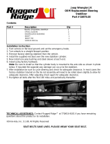
4. Disconnect OEM front sway
bar end link at lower axle
mount using a 18mm socket \
wrench. (See Photo # 1)
5. Disconnect OEM front track
bar from lower passenger
side axle mount using a
21mm socket \ wrench.
(See Photo # 2)
6. Note: If installing a Skyjacker
OEM Replacement Steering
Stabilizer, remove OEM
steering stabilizer using a
18mm socket \ wrench.
(See Photo # 3)
7. Remove OEM front shock.
Disconnect at lower axle
mount using a 18mm socket \
wrench & at upper frame
mount a 14mm socket \
wrench. (See Photo # 4)
8. Tech Note: On some
models, it will be necessary
to remove OEM brake line
bracket to allow coils to be
removed.
Disconnect OEM front brake
line bracket using a 10mm
socket \ wrench.
Note: 2007-10 Models: Disconnect from frame rail mount.
2011-18 Models: Disconnect from axle mount below coil spring.
Photo # 1 Photo # 2
Photo # 3
Photo # 4

I-JK200BP REV9 06/22 Page 4 of 10
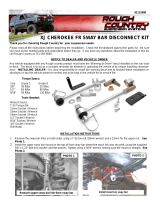
9. On RUBICON Models: Disconnect OEM front axle locker sensor & some of the line clips. (See
Photo # 5)
Tech Note: Red safety lock
clip must be slid rearward to
unlock. Press & hold
rearward tang down, grab
connector & pull away while
from plug-in.
10. Tech Note: On some
models, it will be necessary
to disconnect OEM front
drive shaft to ensure the
drive shaft does not bind when installing taller springs. Mark the location of OEM front drive
shaft \ flange at axle & disconnect using a 15mm socket \ wrench. (See Photo # 6)
11. While checking for appropriate slack in ABS lines, brake lines, differential vent hose & etc,
lower the front differential & remove OEM front coil springs.
12. Place Skyjacker # BSS3020-S Front Bump Stop Spacer on top center of OEM lower coil spring
mount pad. Measure, mark & center punch OEM lower coil spring mount pad. (See Photo # 7)
Drill center mark using a 25/64" drill bit. (See Photo # 8)
13. Place Skyjacker Front Bump Stop Spacer inside Skyjacker # JL10FS-DR Front Coil Spring.
Install front coil spring with bump stop inside. Insert coil spring into upper tower first. Be sure
that the coil & OEM spring isolator are indexed to seat properly, then raise axle enough to hold
coil spring in place. Tech Note: If front axle cannot be lowered enough to allow coil spring to
be installed, carefully rotate the pinion up to provide more clearance for coil installation.
Insert supplied 3/8" x 2-3/4" Button Head Bolt into bump stop. Align bolt into hole of OEM lower
coil spring mount pad. Reach under spring mount pad & above axle tube to install supplied
3/8" SAE Washer & 3/8" Nylon Insert Lock Nut onto bolt. Tighten bump stop into place using a
7/32" hex key socket \ wrench & 9/16" socket \ wrench. (See Photo # 9) Torque 25 ft.-lbs.
14. Raise front axle in order to load Skyjacker front coil springs.
15. Align marks on OEM front drive shaft \ flange & connect drive shaft with OEM hardware using
a 15mm socket \ wrench. (See Photo # 6) Torque 81 ft.-lbs.
16. If installing replacement Skyjacker Steering Stabilizer, install now per separate instructions.
NOTE:
Kit With HYDRO, NITRO, Black MAX, or M95 Monotube: Proceed to Step 17.
Kit With ADX 2.0 Remote Reservoir: Proceed to Step 18.
Photo # 5 Photo # 6
Photo # 7 Photo # 9Photo # 8

I-JK200BP REV9 06/22 Page 5 of 10
17. Install Skyjacker front shock at upper shock tower mount with supplied stud bushings, cup
washers & nut using a 14mm socket \ wrench. (See Photo # 10)
Connect Skyjacker shock at lower axle mount with OEM hardware using a 18mm socket \ wrench.
Secure, but Do Not Completely Tighten at this time. To set bushings properly for ride height,
these will be tightened once vehicle is on ground with full vehicle weight on tires \ wheels.
18. Install Skyjacker ADX front shock. Tech Note: ADX Remote Reservoir are to be mounted with
the remote reservoir toward rear for proper clearance (opposite side of coil spring mount). (See
Photo # 11 & # 12)
Loosely assemble two (2) supplied reservoir clamps with two (2) supplied hex head bolts using
a 5/32" Hex Key socket. Position clamp into place around shock & reservoir cylinder. Secure,
but Do Not Completely Tighten at this time.
Install Skyjacker ADX front shock at upper shock tower mount with supplied stud bushings, cup
washers & nut using a 14mm socket \ wrench.
Connect Skyjacker shock at lower axle mount with OEM hardware using a 18mm socket \
wrench. Secure, but Do Not Completely Tighten at this time. These will be tightened once
vehicle is on ground with full vehicle weight on tires \ wheels.
19. Connect OEM front brake line bracket with OEM hardware using a 10mm socket \ wrench.
20. On RUBICON Models: Connect front axle locker sensor. Note: Pull out on connector to verify
that it is securely plugged in properly. (See Photo # 5)
21. Install the front tires \ wheels using a 19mm socket & lower the vehicle to the ground.
22. Make sure that tires \ wheels are pointed straight ahead. Connect OEM front track bar to axle
mount with OEM hardware using a 21mm socket \ wrench. (See Photo # 2) Secure, but Do Not
Completely Tighten at this time. Tech Note: It may be necessary to turn steering wheel to
align track rod end with mount.
23. Connect OEM front sway bar end link at lower axle mount with OEM hardware using a 18mm
socket \ wrench. (See Photo # 1)
Photo # 10 Photo # 11 Photo # 12

I-JK200BP REV9 06/22 Page 6 of 10
Rear Installation: Note:
Save all factory components & hardware for reuse, unless noted.
1. Chock front tires \ wheels. Raise rear of vehicle & support frame rails using jack stands at
indicated lift points in OEM
service manual.
2. Remove rear tires \ wheels
using a 19mm socket.
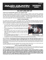
3. Remove OEM rear shock.
Disconnect at lower axle
mount using a 18mm socket \
wrench & at upper frame
mount a 16mm socket \
wrench. (See Photo # 13)
4. Disconnect OEM rear sway bar end link at axle mount using a 18mm socket \ wrench. (See
Photo # 14)
5. Disconnect OEM brake line bracket from frame mount using a 10mm socket \ wrench. (See
Photo # 15)
6. Disconnect OEM rear track bar at axle mount using a 21mm socket \ wrench. (See Photo # 16)
7. Lower the rear differential. Remove OEM rear coil spring & upper coil spring isolator.
8. Install Skyjacker # JK24RTB-B Rear Lower Track Bar Bracket over OEM rear lower track bar
bracket at axle. (See Photo # 17)
With Skyjacker bracket seated flush, clamp Skyjacker bracket & OEM bracket together in using
locking C-clamp pliers. From the top side, use the Skyjacker bracket hole as a guide & mark /
center punch the OEM bracket. (See Photo # 18)
Remove Skyjacker bracket & drill axle mount using a 15/32" drill bit. (See Photo # 19)
Photo # 13
Photo # 14 Photo # 15 Photo # 16
Photo # 18 Photo # 19Photo # 17

I-JK200BP REV9 06/22 Page 7 of 10
9. Insert supplied 7/16" x 1" Fine Thread Bolt down through bracket \ axle mount. Attach with
7/16" SAE Washer & 7/16" Nylon Insert Lock Nut using a 5/8" socket \ wrench. (See Photo # 20)
Torque 60 ft.-lbs.
10. With bracket \ axle mount tightly in place, use the OEM bracket hole as a guide & mark / center
punch the Skyjacker bracket. Drill mount hole using a 17/32" drill bit. (See Photo # 21)
Insert supplied 1/2" x 1-1/4" Fine Thread Bolt with 1/2" SAE Washer outside & 1/2" Nylon Insert
Lock Nut inside using a 3/4" socket \ wrench. Secure, but Do Not Completely Tighten.
Insert supplied 9/16" x 3-1/2" Fine Thread Bolt with 9/16 SAE Washer from rear-to-front
through bottom hole of bracket \ axle mount.
Place #CS1625 Crush Sleeve inside OEM mount & insert bolt through bracket \ axle mount.
Attach with 9/16" SAE Washer & 9/16" Nylon Insert Lock Nut using a 13/16" & 7/8" socket \
wrench. (See Photo # 22) Tighten All Mounting Hardware.
11. Install Skyjacker # JK25RBS-S Rear Bump Stop Spacer to OEM axle bump stop pads with
supplied 5/16" x 1" Fine Thread Bolt with a 5/16" SAE Washer & a 5/16" SAE Washer with
5/16" Nylon Insert Lock Nut using 1/2" wrenches. (See Photo # 23)
Note: Install Skyjacker bump stop spacer with angle cut forward toward front of vehicle.
12. Install Skyjacker rear coil spring. Be sure coil spring is seated properly at lower axle mount by
rotating the coil until the pigtail hits the spring stop. Note: Be sure OEM upper coil spring
isolator is properly aligned with coil & upper coil spring mount. (See Photo # 24)
Raise rear axle to load Skyjacker rear coil springs.
13. Connect OEM rear track bar to Skyjacker bracket with supplied 9/16" x 3" Fine Thread Bolt
with 9/16 SAE Washer from front-to-rear through lower hole of bracket. Attach with 9/16" SAE
Washer & 9/16" Nylon Insert Lock Nut using a 13/16" & 7/8" socket \ wrench. (See Photo # 25)
Secure, but Do Not Completely Tighten. Tech Note: It may be necessary to raise \ lower axle
to align track bar bolt. A rachet strap can be helpful to align track bar / bracket together.
Photo # 21 Photo # 22Photo # 20
Photo # 24 Photo # 25Photo # 23

I-JK200BP REV9 06/22 Page 8 of 10
14. Attach OEM brake line to the frame with OEM hardware using a 10mm socket \ wrench. (See
Photo # 15)
15. Attach OEM rear sway bar end links with OEM hardware using a 18mm socket \ wrench. (See
Photo # 14)
NOTE:
Kit With HYDRO, NITRO, Black MAX, or M95 Monotube: Proceed to Step 16.
Kit With ADX 2.0 Remote Reservoir: Proceed to Step 17.
16. Install Skyjacker rear shock. Connect upper shock mount with
OEM hardware using a 16mm socket \ wrench. Connect lower
shock mount with OEM hardware using a 18mm socket \
wrench. (See Photo # 26) Secure, but Do Not Completely
Tighten at this time. Tech Note: Black MAX & M95
Monotube are to be mounted with cylinder body up for proper
installation of pre-installed upper mount bushings.
17. Tech Note: ADX Remote Reservoir shocks are to be
mounted with cylinder body up. Remote reservoir is to be
mounted toward rear of vehicle & rotated inward for proper
clearance. (See Photo # 27)
Loosely assemble two (2) supplied reservoir clamps with two
(2) supplied hex head bolts using a 5/32" Hex Key socket.
Position clamp into place around shock & reservoir cylinder.
Secure, but Do Not Completely Tighten at this time.
Install Skyjacker ADX rear shock. Connect upper shock
mount with OEM hardware using a 16mm socket \ wrench.
Connect lower shock mount with OEM hardware using a
18mm socket \ wrench.. Secure, but Do Not Completely
Tighten at this time.
18. Install the rear tires \ wheels using a 19mm socket & lower the vehicle to the ground.
Final Clearance Check & Torque Steps:
Note: Check Front Center Axle Disconnect (CAD) connection & on RUBICON Models: Check
Front & Rear locker connections.
The Drag Link Must Be Adjusted to Center the Steering Wheel Before the Vehicle Is Driven.
Failure to Do So Will Cause Computer Errors, Odd Handling Characteristics, & Poor
Performance.
1. Start vehicle. Make sure there are no dash lights pertaining to suspension.
2. Jounce vehicle a couple of times. This will help suspension settle to new ride height. Cycle
steering lock-to-lock & check all components for proper operation & clearances. Pay special
attention to clearance between tires \ wheels, ADX Shocks & Reservoirs, control arms, brake
hoses, ABS wiring, etc.
Photo # 26
Photo # 27

I-JK200BP REV9 06/22 Page 9 of 10
3. Front Tighten & Torque Sequence.
Skyjacker track bar at axle using a 21mm socket \ wrench. Torque 125 ft-lbs.
Front shock absorber upper mount using a 14mm socket \ wrench. Torque 32 ft-lbs.
Front shock absorber lower mount using a 18mm socket \ wrench. Torque 74 ft-lbs.
ADX Reservoir clamp. Double check position & clearance. Tighten with 5/32" Hex Key socket.
Sway bar end link lower bolt using a 18mm socket \ wrench. Torque 59 ft-lbs.
4. Rear Tighten & Torque Sequence.
Skyjacker track bar bracket bolts. 1/2" Bolt Torque 90 ft-lbs. 9/16" Bolt Torque 130 ft-lbs.
Track bar at Skyjacker bracket using a 13/16" & 7/8" socket \ wrench. Torque 130 ft-lbs.
Rear shock absorber upper mount using a 16mm socket \ wrench. Torque 45 ft-lbs.
Rear shock absorber lower mount using a 18mm socket \ wrench. Torque 74 ft-lbs.
ADX Reservoir clamp. Double check position & clearance. Tighten with 5/32" Hex Key socket.
Sway bar end link lower bolt using a 18mm socket \ wrench. Torque 59 ft-lbs.
Final Notes:
• After installation is complete, double check that all nuts & bolts are tight. Refer to the following
chart for proper torque specifications. (Note: Do not re-tighten nuts & bolts where thread lock
compound was used.)
• With vehicle placed on ground, cycle steering lock to lock & inspect steering, suspension, brake
lines, front & rear drivelines, fuel lines & wiring harnesses for proper operation, tightness &
adequate clearance.
• Have headlights readjusted to proper settings.
• Have a qualified alignment center align vehicle to OEM specifications.
• After first 100 miles, check all hardware for proper torque & periodically thereafter.
Seat Belts Save Lives, Please Wear Your Seat Belt.
TORQUE SPECIFICATIONS
INCH SYSTEM METRIC SYSTEM
Bolt Size Grade 5 Grade 8 Bolt Size Class 8.8 Class 10.9
5/16 180 in-lbs 240 in-lbs 6MM 102 in-lbs 108 in-lbs
3/8 30 ft-lbs 35 ft-lbs 8MM 16 ft-lbs 23 ft-lbs
7/16 45 ft-lbs 60 ft-lbs 10MM 32 ft-lbs 45 ft-lbs
1/2 65 ft-lbs 90 ft-lbs 12 MM 55 ft-lbs 75 ft-lbs
9/16 95 ft-lbs 130 ft-lbs 14MM 85 ft-lbs 120 ft-lbs
5/8 135 ft-lbs 175 ft-lbs 16MM 130 ft-lbs 165 ft-lbs
3/4 185 ft-lbs 280 ft-lbs 18MM 170 ft-lbs 240 ft-lbs
The Above Specifications Are Not to Be Used
When the Bolt Is Being Installed With a Bushing.

I-JK200BP REV9 06/22 Page 10 of 10
1/10