Page is loading ...

RUBICON EXPRESS 3290 MONIER CIR., RANCHO CORDOVA, CA. 95742 916-473-4600
INSTALLATION INSTRUCTIONS FOR:
RE7500 SERIES TJ EXTREME DUTY LONG ARM
TRI-LINK SYSTEM INCLUDING TJ UNLIMITED
Congratulations on purchasing the ultimate suspension upgrade available for the Jeep TJ.
Application Notes:
1) The TJ long arm system was originally designed for 5.5” lift. The front track bar may be marginally long for the 4.5” lift. The male
thread of the RE1610 bar can be shortened by about 3/8” to allow shortening the bar to better center the axle.
2) It is highly recommended that a slip-yoke eliminator and CV drive shaft be used in conjunction with this lift.
3) This kit requires modifications to the exhaust system. Generally, after the suspension is installed, plan on a shop installing a
system from the rear of the cat on back with a smaller muffler.
4) The “Rubicon” model TJ’s will require that the installer fabricate a bracket to relocate the compressor (refer to Photo 2 for an
example). Also, “Rubicon” model TJ’s with automatics will have to remove the transmission skid plate for drive shaft clearance. If
more transmission protection is required, the installer will have to fabricate it.
Safety Warning:
Suspension systems or components that enhance the off-road performance of your vehicle may cause it to handle differently, on and off-road, than it did
from the factory. Care must be taken to prevent loss of control or vehicle rollover during sudden maneuvers. Failure to drive the vehicle safely may result
in serious injury or death to driver and passengers. We recommend you always wear your seat belt, drive safely and avoid quick turns and other sudden
maneuvers. Constant maintenance is required to keep your vehicle safe. Thoroughly inspect your vehicle before and after every off-road use.
Installation Warning:
We recommend that certified technicians perform the installations of our products. Attempts to install these products without knowledge or experience
may jeopardize the safety of the vehicle. These instructions only cover the installation of our products and may not include factory procedures for
disassembly and reassembly of factory components. Read instructions from start to finish and be sure all parts are present before disassembling the
vehicle. Included instructions are guidelines only for recommended procedures and in no way are meant to be definitive. Installer is responsible to insure a
safe and controllable vehicle after performing modifications. Do not perform test drives on public roads with partially completed installations. Always
double and triple check your work before use.
KIT CONTENTS
Front Coil Springs 4.5” Kit: RE1355, 5.5” Kit: RE1352
Rear Coil Springs 4.5” Kit: RE1360, 5.5” Kit: RE1353
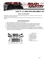
RE1155 (4.5” kits) or RE1156 (5.5” kits) Sway Bar End Links
RE1142 Gen2 Sway Bar Disconnects
RE1383 Bump Stops Front lower 3” (4.5” and 5.5” kits)
RE1385 Bump Stop spacers Rear 1.5”
RE1395 Bump Stops Rear 1.5” Extended
RE1517 Brake Line SS Rear 24”
RE1550 Brake Line SS Front 22”
RE1610 Front Extreme Duty Track Bar
RE1611 Front Extreme Duty Drop Track Bar Bracket
RE2035 Rear Shock Relocation Mount
RE2500 Drop Pitman Arm
RE4000 Extreme Duty Control Arm Front Lower Left
RE4010 Extreme Duty Control Arm Front Lower Right
RE4020 Extreme Duty Control Arm Front Upper, pair
RE4030 Extreme Duty Control Arm Rear Lower, pair
RE4045 Extreme Duty Control Arm Rear Upper Tri-Link, pair
RE4100 (’97-’02 models) or RE4200 (’03-’06 models) TJLA Belly Pan side plates
RE4102 (’97-’02 models) or RE4202 (’03-’06 models) TJLA Belly pan center section
RE4400 (’97-“02 models) or RE4405 (’03-’06 models) Tri-Link Rear Truss Kit
TYPICAL TOOLS REQUIRED
1” hole saw(s) for steel, ½” drill motor & drill bits (including a high quality 5/8” bit), angle grinder,
Basic mechanical hand tools and T-55 Torx head bit along with standard Torx head wrench set,
Floor jack & jack stands (2 Pair), Pitman arm puller, welder
Plasma cutter, or reciprocating saw w/metal cutting blades, or cutting wheels for angle or die grinder (to remove control arm mounts)
RI7500 Page 1 of 9

PRE INSTALLATION NOTE:
Control arm bushings are pre-lubed during initial assembly at Rubicon Express. As general maintenance the control arm bushings should be
lubed with a silicone base grease as needed. Silicone base grease can be purchased at your local auto parts store.
The Super-flex joints are also pre-lubed during initial assembly at Rubicon Express. As general maintenance the super-flex joints should be
greased as needed and the outer spanner nut tightened on the joint. Any type of grease will work on the Super-flex joints. Spanner nut
tools are available through Rubicon Express (RE3771 & RE3772) if needed for tightening of the joints.
INSTALLATION OVERVIEW
The installation process can be broken down into the following tasks:
1. Removal of factory lower control arm mounts on frame.
2. 3-piece frame crossmember.
3. Front Control arms.
4. Rear Truss Assembly
5. Rear Control arms
6. Bump stops and coils.
7. Track bars, pitman arm and sway bar links.
8. Brake lines and shocks.
9. Final detailing and adjustments.
Step 1 - Removal of factory lower control arm mounts on frame
A. First, support vehicle by frame (preferably on a lift) and work on a stable level surface. Support axles with jack stands and
remove the following components; shocks, track bars, sway bar end links, coil springs, lower control arms, bump stops, rear
drive shaft, and exhaust system behind the catalytic converter. NOTE: Coil springs can be removed without compressors if
enough distance is generated between the axle and frame). If a lift is not being used, it may be easier to do this one side at a
time on one axle at a time. CAUTION: If using coil spring compressors use extreme care as they will be holding a lot of potential
energy and can release violently.
B. Cut off the (4) factory lower control arm mounts from the frame. Use extreme care as not to damage the frame, or cut into
existing brake, fuel, or electrical lines. If deep gouges are made in the frame during removal we recommend that they be welded
back up and sanded smooth. ( Photo 1)
C. Grind rough areas smooth and repaint – refer to Photo 1 for typical bracket removal.
Photo 1 Photo 2
Step 2 - 3-piece frame crossmember
A. Support transmission and transfer case and remove stock crossmember. Note that the “Rubicon” model TJ’s will require that the
installer fabricate a bracket to relocate the compressor. (Photo 2)
B. Assemble the right and left control arm mounts to the center section using only a few supplied flat head bolts for fitment
purposes .We will refer to this assembly from here on out as the “cross member”. (Photo 3, RE4200 shown)
RI7500 Page 2 of 9

Photo 3 Photo 4
C. Install cross member using the six factory mounting bolts. Using a transfer punch or center punch mark the location for the two
recess holes to be drilled. These holes will be centered between the front and middle, middle and rear factory frame nut
locations. Remove the cross member and with a 1” hole saw drill the recess holes thru the bottom of the frame. (Photo 4)
D. Loosely install the side “L” bracket with the supplied ½” x 1.25” bolts and flat washers to the cross member. Raise the cross
member back up to the frame and bolt securely to the frame with the supplied ½”-13 (97-02, RE4100) or 12mm (03-06, RE4200)
bolts. Check to see that the cross member is centered under the frame and the “L” brackets are snug against the sides of the
frame rails and mark the three drill locations.
E. Using the 1” hole saw drill the outside of the frame rail to accept the 1” frame sleeves. Use a spare ½” bolt and nut to guide the
frame sleeve thru the 1” hole, square the spacer with the inside of the frame rail and weld into place. Sand the outside smooth
and paint. (Photo 5, prior to welding)
F. Use a ½” drill bit and the welded frame spacer as a guide drill thru the spacer and into the inside section of the frame rail.
CAUTION! The driver’s side frame rail has FUEL, BRAKE, and ELECTRICAL running along its length from front to rear.
Be sure that all of these lines are moved out of the way before proceeding with drilling thru the frame rail.
Photo 5 Photo 6
G. You are now ready to permanently install the cross member. Start the installation by mounting the transmission mount adapter
plate to the top side of the cross member center section using the supplied 6 plow head bolts, flat washers, and lock nuts.
(Photo 6) RE4100 with auto trans location shown
NOTE: Early model vehicles (1997-2002, RE4100) will have two possible locations to mount the transmission adapter
plate to. For automatic transmission mount the plate to the forward location, manual transmissions mount to the
rearward location. Late model vehicles (2003-2006, RE4200) only have one possible location, in both cases mount the
plate with the raised lip forward.
H. A total of 10 bolts will be used through bottom of frame braces and crossmember, and a total of 6 bolts will be used through side
of frame braces and frame rails, eight total per side. (Photo 7)
I. Install all remaining flat head bolts in each side of the side plates to center section and lower the transmission down to the cross
member. Re-install the four factory transmission mount nuts.
RI7500 Page 3 of 9

Photo 7 Photo8
Step 3 – Front control arms
A. FRONT - Adjust front lower control arms’ length to an initial setting of 37.5” from bolt center to bolt center. Final arm lengths
seem to vary from around 37.5” to 38” depending on lift, axle squareness (see step C) and differential clearance to track bar.
Install adjustable end of arm to front crossmember with supplied hardware (zerk on top). Position the arms so the welded on
brackets for the front upper arms are on top and leaning toward each other. Photo 8
B. Adjust front upper control arms’ length to an initial setting of 15-7/8” from bolt center to bolt center. Install front upper arms’
rubber bushing end into the welded on bracket of the lower arms with supplied hardware. The upper arms will be used to adjust
final caster and pinion angle.
C. Attach front lower control arms to axle with the supplied hardware (bag kit 50), and attach upper arms to axle with supplied
hardware (bag kit 21) Checking distance from axle mount to front factory crossmember bolt should verify if axle is square, adjust
if necessary.
Tri Link Truss installation
Step 1 – Cross member modifications
A. Install the right and left upper control arm relocation brackets into the cross member where the upper arms would normally
attach to. New 10mm bolts and lock nuts are supplied. (Photo 9)
Photo 9
Photo 10
B. Locate the position of the relocation bracket supports on the frame or cross member. Mark the frame (97-02) or cross member
(2003+) and drill the necessary holes. Using the supplied hardware, loosely install the brackets. (Photo 10) 03-03 shown
Step 2 – Rear truss assembly
A. With the upper control arms removed and axle lowered, sand the top of the upper control arm brackets flat, removing the ears
from the top front edge. Next, sand the tabs on the outer edges of the brackets to be smooth with the bracket. Then drill out the
hole in the upper control arm mount to 7/16”. Photo’s 11 & 12
RI7500 Page 4 of 9

Photo 11 Photo 12
B. Loosely pre-assemble the rear truss assembly. Attach the left and right control arm brackets, upper pivot support, and the correct
differential cover bracket. The rear truss kit includes both the D35 and D44 cover bracket. You will need to select the correct
differential cover bracket from the kit for your vehicle. (Photo 13) D35 cover bracket shown
Photo 13
C. Remove the upper three differential cover bolts and lower the truss assembly over the upper control arm brackets. Insert the two
upper bolts through the control arm brackets, then using the supplied 5/16”x1” bolts, align the rear cover bracket and lightly
tighten the bolts. Tighten the two ½” bolts that go through the control arm brackets and main truss. Mark and drill the four
additional holes on the control arm mounts. (Photo 14)
Photo 14 Photo 15
D. Insert the four 7/16” bolts through the upper and lower holes in the brackets using the supplied spacers to keep the factory axle
brackets from collapsing. Once all hardware is installed, tighten all but the three of the upper pivot support brackets. (Photo 15)
RI7500 Page 5 of 9

NOTE: Do not install all of the upper pivot support bolts at this time. Leaving two bolts out and swinging the
bracket out of the way will assist in installing the upper link assembly. Once the assembly is in place and
axle centered, install and fully tighten all hardware.
Step 3 – Rear arm installation
A: UPPER TRI-LINK - Pre-assemble the two upper arms (RE4045) to the HD S/F ball assembly. The main pivot assembly will connect
to what will now be the right upper arm; the threaded coupler with the ½” sleeve welded to it will be the left upper arm. It is
recommended that the ½” bolt be installed from the bottom up for maximum clearance. Set both arms at an equal distance from
center of end to center of end, approximately 34 ¼” - do not tighten the jam nuts at this time. (Photo 16)
Photo 16
NOTE: It is very important that 1” of thread contact be maintained between the upper arms and the pivot assembly. Less
than 1” of contact may result in a failed connection.
B. Remove two of the bolts from the upper pivot support bracket and slide the upper arm link assembly into the upper control arm
pockets. Install supplied ½” x 4” bolts through the upper arm mount and mount support bracket.
C. Install 5/8” bolt through upper pivot support bracket and main truss to fully secure upper assembly. Photo 17
D. Install the ½” bolt up from the bottom of the pivot ball through the control arm coupler for maximum clearance. Photo 18
Photo 17 Photo 18
E. Without coil springs in the vehicle raise the axle into ride height position, approximately 12-13” distance between upper and lower
spring cups. With a string line or straight edge, measure axle center off the side of the frame down to the axle. Make sure that
your axle measuring point is the same on both sides.
F. If your axle is off-center to the driver’s side, lengthen the driver’s side arm and shorten the passenger’s side arm, or vice versa.
Keep in mind that increasing or decreasing the length of the upper arm assembly will affect the pinion angle. Once centered, and
thread contact into the pivot assembly threads is confirmed, use the lower arms to fine-tune pinion adjustment.
G. Once all adjustments are made, verify that all brackets are installed and hardware is tight.
NOTE: The ½” bolt on the end of left upper control arm coupler that connects to the pivot must be tightened
after final adjustments are made. This attachment point is not designed to be left loose as a pivot itself.
RI7500 Page 6 of 9

Step 5 – Rear arm installation
A. REAR - Adjust rear lower control arms’ length to an initial setting of about 32-5/8” from bolt center to bolt center. Final arm
lengths seem to vary from around 32-5/8” to 33.25” depending on lift, axle squareness, tire size, and gas tank clearance. Install
adjustable end of arm to rear crossmember lower mounts with supplied hardware (zerk on bottom).
LJ UNLIMITED - Adjust rear lower control arms’ length to an initial setting of about 42-5/8” from bolt center to bolt center. Final
arm lengths seem to vary from around 42-5/8” to 43-1/4” depending on lift, axle squareness, tire size, and gas tank clearance.
Install adjustable end of arm to rear crossmember lower mounts with supplied hardware (zerk on bottom).
Step 6 – Bump stops and coils
A. REAR BUMP STOPS - Remove the rubber insert from the rear bump stop. Remove the bump stop cup. Place the spacer between
the bump stop cup and the tower using the supplied longer metric hardware, install RE1395 extended bump stops into the factory
cups.
B. Install rear coil springs into factory location, either side up or down. (Photo 19)
Photo 19 Photo 20
C. FRONT BUMP STOPS - Drill 5/16” hole in center of lower spring pads. Use self-tapping bolt through bump stop to cut threads in
lower spring pad. Remove bolt and spacer, it will be installed with the spring. (Photo 20)
D. FRONT COILS - Install the front coils with the bump stop inside of the coil. Coil spring compressors may be useful. Once the
spring is in place, put the bolt through the bump stop extension and thread the bolt into the lower spring pad. Be sure to rotate
the coil to index the spring with lower coil cup, and reinstall coil spring retainer if removed earlier.
Step 7 – Track bars and sway bar links
A. FRONT TRACK BRACKET – drill out factory bracket to 5/8” with a high quality bit and some cutting fluid (or similar). Slide the
track bar bracket over the frame and insert the supplied 5/8” bolt thru the bracket and factory track bar hole, tighten securely.
Drill ½” holes through the frame at the two holes in the new bracket being sure holes are perpendicular to the frame. Attach new
bracket to the frame with supplied ½” hardware (Photo 21)
B. FRONT TRACK BAR – Using a ½” drill bit drill out the factory track bar mounting location on the axle end. Attach new track bar to
lower mounting point using the supplied ½” bolt and nut tab, this is the poly-bushing end of bar. Position bar so it starts out
parallel with the axle (horizontal), then turns up toward the frame bracket. Before connecting bar to upper mount, center the
vehicle over the axle by measuring the distance from front fender flare to tire on both driver and passenger sides of the vehicle,
then adjusting vehicle until body is centered over the axle. The easiest way to accomplish this is when the vehicle is back on its
wheels, have an assistant turn steering wheel left or right as necessary. Adjust spherical bearing end so that it will fit directly into
the upper mount with the body centered. Tighten the jam nut to prevent the spherical bearing end from moving on the threads.
Use supplied ½” hardware to attach RE1610 to new bracket.
RI7500 Page 7 of 9

Photo 21 Photo 22
C. Install rear sway bar links in the same fashion as the factory links using the factory hardware.
D. Install front sway bar quick disconnects per instructions supplied with disconnects (Photo 23).
Photo 23 Photo 24
Step 8 – Shocks and brake lines
A. Install longer front shocks. Some require bar pins to be installed through the bottom shock eyes (use light grease).
B. Position and weld on rear shock mounts (Photo 24) for typical installation. The slot in the bracket is provided to place over
control arm bracket, but different shocks or lengths may require different positions. Generally, the mounts end up in the
neighborhood of 45 degrees, but it’s better to check that there is about 1” of shock travel remaining when the bump stops are
touching their pads. Install longer rear shocks.
C. Fully remove front factory brake hoses and replace with the supplied stainless steel hoses. Some require positioning the block and
line vertically at the caliper. Watch line routing so they do not catch on anything during axle articulation. Use angle brackets and
e-clips at the frame end if necessary
D. Remove factory rear brake line and replace with the supplied line. Watch the routing so it does not catch on anything during axle
articulation.
Step 9 - Final details and adjustments
A. Install wheels and lower vehicle.
B. Adjust the track bars to fit into the mounts with the axles as centered as possible (centering is not hyper critical).
C. Thoroughly bleed brake lines per factory manual and check for leaks and a firm pedal.
D. Torque all bolts to factory specs and double-check your work.
E. Test drive and note location of steering wheel and any driveline vibrations.
F. Adjust drag link to center steering wheel and align vehicle as soon as practical. Minimum factory caster and maximum factory toe-
in seems to work well with these front ends (see Troubleshooting as well).
RI7500 Page 8 of 9

G. Adjust control arms if necessary. Note: Due to vehicle variations installer must verify proper driveline angles and axle placement
to avoid tire rubbing or axle coming in contact with gas tank, steering linkage, or exhaust system. Shown below is picture
showing proper pinion angle for a CV style drive shaft (see Troubleshooting as well).
H. Retighten all bolts after 50 miles and again after every off road excursion.
TROUBLESHOOTING
Rear driveline:
Acceleration vibration: Caused by the pinion being too high in relation to the transfer case output shaft. Adjust upper control arm to lower
pinion accordingly.
Deceleration vibration: Caused by the pinion being too low in relation to the transfer case output shaft. Adjust upper control arm to raise
pinion accordingly.
Slip yoke vibration: Caused by excessive angle on the transfer case slip yoke. This is not uncommon on lifted vehicles with some miles on
them. For best performance, install a slip yoke eliminator (SYE) kit and CV drive shaft. Adjust pinion so it is about 2 degrees below parallel
with CV drive shaft (see acceleration and deceleration vibration troubleshooting above).
High speed wobble:
It is a condition where front tires will shimmy after hitting a bump. Avoid bias ply tires and wheels with excessive offset. Check for worn or
loose parts. In most cases a reduction of positive castor will eliminate this condition.
Bump steer: Caused by improper relationship of drag link and track bar. To correct, center axle again following the instructions supplied
with the track bar. Next determine the neutral position of the steering wheel. Adjust the drag link to center the steering wheel. NOTE: A
drop pitman arm should NOT be used on kits using the RE1600 front track bar in the factory mounts, as this will cause bump steer.
RI7500 Page 9 of 9
/