Page is loading ...

Technical Note: SecureSync
Troubleshooting GPS/Glonass reception issues with the
Spectracom SecureSync
www.spectracomcorp.com 1 | SecureSync GPS reception troubleshooting
Purpose: The purpose of this document is to provide detailed information on troubleshooting GPS reception-related
issues with Spectracom SecureSync.
Spectracom SecureSyncs can be purchased with an internal GPS receiver (prior to ~ April 2014) or GNSS receiver
(starting ~ April 2014) that allows GPS (and with a GNSS receiver installed, optionally Glonass as well) to be a primary
input reference for synchronization. When using GPS/Glonass as an input reference, there are a few factors that can
inhibit reception in the Spectracom SecureSync. Satellite reception problems can be caused by faulty antenna cable
connections or by the type of antenna cable in use. They may also be a result of the overall length of the antenna
cable. Other potential causes of reception issues include the physical position of the antenna and proximity to local
sources of interference. This Tech Note is intended to assist Spectracom customers in troubleshooting issues
concerning satellite reception.
If your installation includes either a Spectracom Model 8228 window-mount GPS antenna, or Models 8230 or 8225
outdoor antenna placed in a window, initially skip Sections 1 and 2 of this document and refer first to Section 4.
Note: Archive software version 5.1.2 introduced a new design of the web browser interface. Section 1 discusses
Archive software versions 5.1.2 and above for the newer web browser interface, while Section 2 discusses
Archive software versions 5.0.2 and below with the classic interface web browser.
TABLE OF CONTENTS
Section 1: Identifying a GPS Reception Issue exists (Software versions 5.1.2 and above) ............................................... 2
Section 2: Identifying a GPS satellite reception issue exists (Archive versions 5.0.2 and below with the “classic
interface” web browser) .............................................................................................................................................. 10
Section 3: Troubleshooting a GPS Reception Issue ......................................................................................................... 18
Process A: Troubleshooting Opens or Shorts in the Antenna Cable ........................................................................... 19
Process B: Troubleshooting Cable “OK” Related Issues .............................................................................................. 27
Specific to only SecureSyncs with a SAASM GPS receiver installed (note this GPS receiver is only available to
qualified US Military/DOD/NATO organizations) ........................................................................................................ 29
Section 4: Using a Model 8228 Window-Mount Antenna with SecureSync ................................................................... 31
Spectracom Technical Support ........................................................................................................................................ 34

www.spectracomcorp.com 2 | SecureSync GPS reception troubleshooting
Section 1: Identifying a GPS Reception Issue exists (Software versions 5.1.2 and above)
After initially connecting the GPS antenna to the SecureSync (with it powered up and running), the front panel Fault
light should not be blinking amber/red (Blinking amber indicates the GPS antenna is not yet connected or an
open/short is present in the antenna cable- Refer to Process A if the Fault LED is blinking red).
About 33-35 minutes after the SecureSync has begun to track at least 4 satellites, the GPS survey will be completed
and the Sync lamp on the front panel should indicate uninterrupted green. The Sync light should remain
uninterrupted green thereafter, unless the SecureSync is power-cycled or the GPS/GNSS antenna is disconnected.
If the Sync lamp does not indicate uninterrupted green after about 40 minutes with the unit initially powered up and
the antenna connected, the SecureSync may not be receiving signal from the minimum number of four satellites
necessary to declare initial time sync. If the front panel Sync light initially indicates uninterrupted green but
periodically turns amber anytime thereafter, the SecureSync may be experiencing intermittent reception issues (with
no other reference inputs available). This condition indicates GPS/Glonass reception issues that need to be
investigated.
Reference Priority table
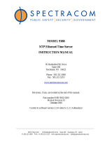
In order for SecureSync to be able to synchronize to GPS and/or Glonass satellites, “GNSS 0” needs to be listed and
enabled in the Reference Priority Setup table (“GNSS 0” is listed and enabled by factory default, if a GNSS receiver
which can track GPS and/or Glonass satellites is installed). To verify “GNSS 0” is enabled, navigate to the
Management -> Reference Priority page of the web browser. The Reference Priority Setup table should display
“GNSS 0” in one row of the table (in both the “Time” and “PPS” columns) and the corresponding “Enabled” field in
that row should be selected.
Figure 1: Reference Priority Setup table
Reference Status table
Make sure that one row of the
table contains “GNSS 0” in both the
“Time” and “1PPS” column and this
row is “Enabled”

www.spectracomcorp.com 3 | SecureSync GPS reception troubleshooting
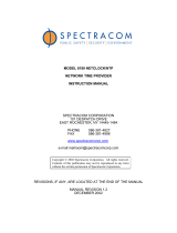
One indication of a GPS/Glonass reception problem occurring is displayed in the “Reference Status” table in the
Home page of the browser (upper-right hand corner of the browser). If satellite reception is fully qualified, both
circles in the “GNSS 0” row will be green (neither will be red).
Figure 2: Input Reference Status page with GPS reception present and valid
The “Reference Status” table displays information on all available input “Time” and “PPS” input references, including
whether the input is enabled or not (per the “Enabled” field), and whether or not the input is present and considered
valid (per the Time and PPS indicators). Reference inputs that are present and considered valid are displayed with a
Green circle (while input references that are either not present or not considered valid are displayed as a Red circle).
In the examples shown in Figures 2 and 3, “GNSS 0” (representing GPS/Glonass input and indicated as “GNSS 0” in
both the “Time” and “PPS” columns) is an “Enabled” reference input. Because both the “Time” and “PPS” boxes for
GPS are shown are Green circles (Figure 2) , GPS and/or Glonass reception is both currently present and considered
valid (the GNSS receiver is currently tracking at least the minimum number of satellites needed for it to be
considered a valid “Time” and “1PPS” reference).
If the GPS/GNSS receiver starts to track less than the minimum number of GPS and/or Glonass satellites (or no
satellites at all), both of the “Time” and “PPS boxes” for “GNSS 0” will go into the ALARM state (red circles) as shown
in the Figure below:
Figure 3: Input Reference Status page with GPS reception either not present or invalid
The most obvious indication that there is a problem with GPS and/or Glonass reception, because of an antenna cable
issue, is that the front panel Fault light will blink amber, if any opens or shorts are detected in the antenna cable. If
this occurs with the SecureSync connected to a GPS antenna, a cable issue exists; refer to Process A. However, if a
GPS splitter is being used to allow a GPS antenna to be shared by more than one SecureSync or other Spectracom
NetClocks, this may be a normal indication caused by the splitter (depending on whether the DC-blocked port
simulates the normal current draw of a GPS antenna using a load resistor).
The SecureSync’s Web Browser User Interface (Web UI) can be used to determine if the Time Server is currently
tracking any satellites. Once the GPS antenna is connected and the unit is powered up, the unit should be tracking at
Both the “TIME” and PPS “GNSS 0” entries indicate “OK”
(Green). This indicates GPS/Glonass reception is present and
the minimum number of satellites is currently being tracked
(GNSS is a valid input reference.
Both the Time and PPS “GNSS 0” entries
have Red circles (alarm state). GPS
and/or Glonass reception is not present
or the minimum number of satellites is
not being tracked.

www.spectracomcorp.com 4 | SecureSync GPS reception troubleshooting
least four satellites within 20 minutes. If it is not tracking at least four satellites with the antenna installed outdoors,
it is likely there is a reception-related issue.
The first step is to determine if the unit is not currently tracking any GPS and/or Glonass satellites at all. Or, if it is
able to track satellites, but it is tracking less than the four required satellites for the survey to be performed.
To determine the number of satellites currently being tracked, log in to the SecureSync’s Web UI. The Interfaces ->
GNSS page of the browser reports the number of satellites being tracked.
Figure 4: GNSS Signal Status view
For a detailed view, from this page, click on the “circled i” ICON in the bottom row, under the photo. Or from the
main menu, click on “Interfaces” at the top of the page and in the drop-down, select “GNSS 0”. The “Main” tab
should be automatically selected (as shown below):
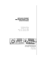
Figure 5: GNSS Signal Status view
This line indicates the number of combined GPS and/or
Glonass satellites currently being used for time/position
fix information.
Mouse-hover over each of the bar graphs to indicate
the satellite ID numbers being used in the fix and their
relative signal strengths (SNR values) for those
particular satellites.
This line indicates whether an open or short is being
detected in the antenna cable (“OK” indicates no cable
issues are being detected at this moment). In this
example, an open in the cable is being detected.
This line indicates the validity of the GNSS receivers
Time and PPS inputs.
GPS or GNSS receiver Model installed.

www.spectracomcorp.com 5 | SecureSync GPS reception troubleshooting
As shown in Figure 5, the “GNSS 0 Input Status” page will indicate the current number of GPS and/or Glonass
satellites being used in the positional fix (based on the number of vertical bars being displayed). If this field indicates
no bars, it is currently not tracking any satellites. If this field indicates a low number of bars, such as only “1”, “2” or
“3”, the unit is tracking a few satellites, but it’s not tracking the minimum number of satellites required for initial
sync.
Distinguishing between GPS satellites and Glonass satellites, when the Glonass Option is enabled
To determine if each bar represents a GPS or a Glonass satellite, Mouse-hover each bar to see a report of three
values (two letters, the Satellite ID number and the signal strength value for that satellite).
➢ GPS satellites are indicated with the two letters of “GP” and have a Satellite ID Number of 0 to 59
➢ Glonass satellites are indicated with the two letters of “GL” and have a Satellite ID Number of 60 and above
Tracking a low number of satellites (but not zero satellites) rules out shorts or opens occurring in the antenna cable
and typically indicates that the antenna’s view of the horizon/sky is obstructed. Once the GPS survey has initially
been completed, the minimum number of satellites drops to just one satellite required from that point forward, even
if the time server is subsequently power cycled.
Also included in the GNSS 0 Status page is an “Antenna Sense” indication. The GNSS receiver can detect opens or
shorts occurring in the antenna cable. Antenna Sense showing “OK” indicates that the antenna is connected with no
opens or short in the cable are being detected at this moment (an intermittent antenna cable issue may not be
displayed here, but will be captured in the Event log). Below is an indication that the GNSS receiver is currently
detecting an open in the antenna cable.
Figure 6: Identified Antenna Sense indicating an Open in the antenna cable
The “Identified Satellite Signal Strengths” table (also displayed on the bottom of this web page) indicates the specific
satellite ID number (“ID”) that each of the 12 channels is assigned to track and the relative signal strength (“SNR”) of
the received signal (greater than about 37 indicates usable signal strength). Mouse-hover over each column to see
these values.
Figure 7: Identified Satellite Signal Strengths Columns
In the example shown in Figure 7, seven satellites are currently being tracked (there are 7 vertical bars displayed).
The satellites ID numbers are obtained by hovering over each green bar. In this particular example, the fourth bar
indicates it represents GPS satellite ID Number 24 with a received signal strength of 45. Light green bars indicates
marginal signal strengths while darker green bars indicate stronger signals.

www.spectracomcorp.com 6 | SecureSync GPS reception troubleshooting
Alarms Log
A second indication of GPS reception issues is based on entries contained in the “Alarms” log. The Alarms Log
contains a list of any minor or major alarms that have been asserted, such as “Not In Sync” and “GPS Antenna
Problem” alarms (if the Antenna Sense circuit detected any shorts or opens in the antenna cable). To view the
Alarms Log, navigate to this page by clicking on “Tools” on the top of the main page and then on “Alarms” in the
dropdown. Refer to Figure 8.
Figure 8: Alarms Log Entries
“GPS Antenna Problem” indicates the antenna sense
circuit has detected that a short or open exists in
the antenna cabling.

www.spectracomcorp.com 7 | SecureSync GPS reception troubleshooting
Events Log
A third indication of GPS reception issues is based on entries contained in the “Events” log. The Events Log contains a
list of event changes, such as loss of time sync and Antenna Problem alarms being asserted (if the Antenna Sense
circuit detected any shorts or opens in the antenna cable). To view the Events Log, navigate to this page by clicking
on “Tools” on the top of the main page and then on “Events” in the dropdown. Refer to Figure 9.
Example entries that may be reported include:
A) “GPS Antenna Problem” indicates the antenna sense circuit has detected that a short or open exists in the
antenna cabling.
B) “Too few GPS Sat” indicates not enough satellites are currently being tracked.
C) “In Holdover” indicates SecureSync was in Sync, but has since lost all external references and is now using
the internal oscillator to derive the time. Outputs are still useable.
D) “No longer In Holdover” indicates either the Holdover period has expired, or GPS reception has been
restored.
E) “Not in Sync” indicates no references are available and the holdover period has since expired. Outputs may
not be useable.
Figure 9: Example Event Log Entries
If the SecureSync has intermittent GPS/Glonass satellite reception issues that are causing all satellite reception to
cease, the Events Log may display “In Holdover” alarms and/or time synchronization alarms. “In Holdover” alarms
indicate the SecureSync appliance is no longer tracking any satellites (and has no other external reference available),
but has not yet declared the loss of Time Sync (the time is being derived from the built-in oscillator and the
SecureSync is still a useable time reference). Time Sync alarms indicate the SecureSync is no longer synchronized and
external devices are likely ignoring the SecureSync as a reference. “Antenna Problem” alarms in this log indicate an
opens or short in the antenna cable is likely present (or the GPS/GNSS antenna is not connected to SecureSync).

www.spectracomcorp.com 8 | SecureSync GPS reception troubleshooting
If both Holdover/Time Synchronization alarms and “Antenna Problem” alarms are present, the likely cause of the loss
of satellite reception is due to an antenna cable issue. If Holdover/Time Sync alarms are present, but Antenna
Problem alarms are not present, the satellite reception issue is unlikely to be due to shorts or opens in the antenna
cable (unless the Antenna Sense circuit has been damaged by a surge/lightning).
Qualification Log
A third indication of GPS reception issues is based on entries contained in the “Qualification” log. This log contains a
running hourly count of the number of GPS and/or Glonass satellites tracked each hour. This history data can be used
to determine if a satellite reception problem exists and whether this is a continuous or intermittent reception issue.
To view the GPS Qualification Log, navigate to this page by clicking on “Tools” on the top of the main page and then
click on the “Qualification”.
GNSS satellite reception may be displayed as cyclic in nature. A cyclic 12 hour pattern of decreased satellite
reception typically indicates that the GNSS antenna has an obstructed view of the horizon. GPS satellites are in a 12-
hour orbit, so if part of the sky is blocked by large obstructions, at the same time every day (at approximately 12 hour
intervals), the GPS reception may be reduced or may vanish altogether. If this occurs, the antenna should be
relocated to afford it an unobstructed view of the sky.
Every hour (displayed in the log as UTC time), SecureSync counts the total number of satellites that were tracked
during that hour. The Qualification log shows the number of satellites that were tracked followed by the number of
seconds that the particular number of satellites were tracked during the hour (3600 seconds indicates a full hour).
The number to the left of the “=” sign indicates the number of satellites tracked and the number to the right of the
“=” sign indicates the number of seconds (out of a total of 3600 seconds in an hour) that the unit was tracking that
number of satellites. For example, “0=3600” indicates the unit was tracking 0 satellites for the entire hour, while
“0=2700 1=900” indicates the unit was tracking one satellite for 900 seconds, but for the remaining portion of the
hour it was tracking zero satellites.
Every hourly entry in the log also contains a quality value, represented by “Q= xxxx” (where x can be any number
from 0000 through 3600). If SecureSync tracked at least four satellites for the entire hour in the standard mode or at
least one satellite for the entire hour in Single Satellite Mode, the Quality value will equal 3600. For every second
SecureSync tracked less than the minimum number of satellites, the value will be less than 3600. The minimum
requirement is one satellite at all times after the unit has completed the GPS survey and indicates “Stationary”. A
minimum of four satellites are required in order for the GPS survey to be initially completed.
If all entries in the Qualification log are displayed as “0=3600”, a constant GPS reception problem exists, so the cause
of the reception issue is continuous. If the unit occasionally shows 0=3600 but at other times shows that 1 through 12
have numbers of other than “0000”, the reception is intermittent, so the cause of the reception issue is intermittent.
If the Quality value normally equals 3600 but drops to lower than 3600 about every 12 hours, the issue is likely
caused by the GPS antenna having an obstructed view of the sky.
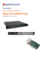
Example GPS Qualification Log entry:
Figure 10: Example GPS Qualification Log Entries

www.spectracomcorp.com 9 | SecureSync GPS reception troubleshooting
In this example entry, SecureSync tracked no less that 5 satellites for the entire hour. Out of the entire hour, it was
tracking 5 satellites for a cumulative total of 60 seconds (not necessarily in a row). For the duration of the hour, it
was tracking, 7 and 8 satellites for a period of time. Because it was tracking at least at least one satellite for the
entire hour, this Quality value is Q=3600.
Note: If SecureSync is not connected to a GNSS antenna (or is never able to start tracking any satellites at
all), the Qualification log will remain empty.
Timing Log
When a Rubidium oscillator is installed in the SecureSync, a fourth indication of a GPS reception issue occurring is the
presence of “Rb track off – free run” and “RB synchronized” log entries in the Timing log. To view the GPS Timing
Log, navigate to this page by clicking on “Tools” on the top of the main page and then click on the “Timing”.
When there are no 1PPS input references present or considered valid (such as the GPS receiver is no longer able to
track at least four satellites), it is not desired to discipline the oscillator to a potentially unstable 1PPS input
reference. To prevent this from happening, when there are no valid 1PPS input references available to SecureSync,
the Rubidium oscillator is automatically placed into a free run state where it is not locked/steered to any 1PPS input
references.
When the oscillator is placed into a free run state, the “Rb track off - - free run” entry is asserted in this log. Once a
valid 1PPS input reference has become available again (such as the GPS receiver is once again tracking at least four
satellites, for example), the “RB synchronized” log entry is asserted into this log. This indicates the oscillator is now
locked and being disciplined to the highest priority input reference that is available to SecureSync.
The Timing log will also report if there are any opens or shorts occurring in the GPS antenna cable, as indicated by
“GPS Antenna” entries being asserted into this log.

www.spectracomcorp.com 10 | SecureSync GPS reception troubleshooting
Section 2: Identifying a GPS satellite reception issue exists (Archive versions 5.0.2 and
below with the “classic interface” web browser)
After initially connecting the GPS antenna to the SecureSync (with it powered up and running), the front panel Fault
light should not be blinking amber/red (Blinking amber indicates the GPS antenna is not yet connected or an
open/short is present in the antenna cable- Refer to Process A if the Fault LED is blinking red).
About 33-35 minutes after the SecureSync has begun to track at least 4 satellites, the GPS survey will be completed
and the Sync lamp on the front panel should indicate uninterrupted green. The Sync light should remain
uninterrupted green thereafter, unless the SecureSync is power-cycled or the GPS antenna is disconnected.
Note: The percentage of the GPS survey that has been completed thus far can be viewed in the “Survey Prog”
field located on the Status -> Inputs -> GPS page of the web browser. 50% complete indicates the survey
will be completed in about 17 minutes (100% is about 34 minutes). Once the GPS survey has been
completed, “Stationary” will be displayed from that point forward (even if the unit is subsequently power
cycled).
If the Sync lamp does not indicate uninterrupted green after about 40 minutes with the unit initially powered up and
the GPS antenna connected, the SecureSync may not be receiving signal from the minimum number of four satellites
necessary to declare initial time sync. If the front panel Sync light initially indicates uninterrupted green but
periodically turns amber anytime thereafter, the SecureSync may be experiencing intermittent GPS reception issues
(with no other reference inputs available). This condition indicates GPS reception issues that need to be investigated.
Reference Priority table
In order for SecureSync to be able to synchronize to GPS, “GPS 0” needs to be listed and enabled in the Reference
Priority Setup table (“GPS 0” is listed and enabled by factory default, if a GPS receiver is installed). To verify “GPS 0”
is enabled, navigate to the Setup -> Reference Priority page of the web browser. The Reference Priority Setup table
should display “GPS 0” in one row of the table (in both the “Time” and “1PPS” columns) and corresponding “State”
value in that row should indicate “Enabled”.
Figure 11: Reference Priority Setup table
Reference Status table
One indication of a GPS reception problem occurring is displayed in the Reference Status table on the Status -> Time
and Frequency page of the browser.
Make sure that one row of the table
contains “GPS 0” in both the “Time” and
“1PPS” columns.

www.spectracomcorp.com 11 | SecureSync GPS reception troubleshooting
Figure 12: Input Reference Status page with GPS reception present and valid
The Reference Status table displays information on all available input “Time” and “1PPS” input references, including
whether the input is enabled or not (per the “State” field), and whether or not the input is present and considered
valid (per the State and 1PPS fields). Reference inputs that are present and considered valid are displayed with “OK”
(Green) while input references that are either not present or not considered valid are displayed as either “ALARM”
(Red) or as “Not Valid” (Orange), depending upon the installed version of software (software version 4.4.0 and above
displays an orange fill with “Not Valid” indicated).
In the examples shown in Figure 11 and Figure 12, “GPS 0” (representing GPS input and indicated as “GPS 0” in both
the “Time” and “1PPS columns”) is an “Enabled” reference input. Because both the “Time” and “1PPS” boxes for GPS
are shown as “OK” (Green), GPS reception is both currently present and considered valid (the GPS receiver is
currently tracking at least the minimum number of satellites needed for it to be considered a valid “Time” and “1PPS”
reference).
If the GPS receiver starts to track less than the minimum number of satellites (or no satellites at all), both of the
“Time” and “1PPS boxes” for “GPS 0” will go into the ALARM state (red or orange, depending on the installed
software version), as shown in Figure 13.
Note: In software versions 4.4.0 and above, if the GPS receiver starts to track less than the minimum number of
satellites (or no satellites at all), both of the Time and 1PPS boxes for “gps0” will go into the “Not Valid” state
(orange fill), as shown in Figure 14.
Figure 13: Input Reference Status page with GPS reception either not present or invalid
Figure 14: Input Reference Status page with GPS reception either not present or invalid
Both of the Time and 1PPS “GPS 0” entries
indicate “OK” (Green). GPS reception is
present and the minimum number of
satellites is currently being tracked.
Both of the Time and 1PPS “gps0” entries
indicate “ALARM” (Red). GPS reception is
not present or the minimum number of
satellites is not being tracked.
Both of the Time and 1PPS “GPS 0” entries
indicate “Not Valid” (Orange fill). GPS
reception is not present or the minimum
number of satellites is not being tracked.

www.spectracomcorp.com 12 | SecureSync GPS reception troubleshooting
The most obvious indication that there is a problem with GPS reception, because of an antenna cable issue, is that
the front panel Fault light will blink amber, if any opens or shorts are detected in the antenna cable. If this occurs
with the SecureSync connected to a GPS antenna, a cable issue exists; refer to Process A. However, if a GPS splitter is
being used to allow a GPS antenna to be shared by more than one SecureSync or other Spectracom NetClocks, this
may be a normal indication caused by the splitter (depending on whether the DC-blocked port simulates the normal
current draw of a GPS antenna using a load resistor).
Note: If any Major alarms are also asserted while the Antenna Problem alarm is asserted, the Fault LED will be lit
solid and will not blink, unless all Major alarms are extinguished.
The SecureSync Web Browser User Interface (Web UI) can be used to determine if the Time Server is currently
tracking any satellites. Once the GPS antenna is connected and the unit is powered up, the unit should be tracking at
least four satellites within 20 minutes. If it is not tracking at least four satellites with the antenna installed outdoors,
it is likely there is a reception-related issue.
The first step is to determine if the unit is not currently tracking any GPS satellites at all. Or, if it is able to track
satellites, but it is tracking less than the four required satellites for the GPS survey to be performed. To determine
the number of satellites currently being tracked, log in to the SecureSync’s Web UI. Click on “Status” at the top of the
page and in the drop-down, select “Inputs”. Then click on “On-Board Reference GPS” (located in the blue box).
Figure 15: GPS Signal Status Page
As shown in Figure 15, the “GPS Input Status” page will indicate the current number of satellites being used in the
positional fix (located just above the table of received satellite data at the bottom of the page). If this field indicates
“0”, it is currently not tracking any satellites. If this field indicates a low number of satellites, such as “1”, “2” or “3”,
the unit is tracking a few satellites, but it’s not tracking the minimum number of satellites required for initial GPS
operation.
This line indicates the number of
satellites currently being used for
time/position fix information.
This table indicates the satellite ID
numbers being used in the fix and
their relative signal strengths (SNR
values) for those satellites.
This line indicates whether an open or
short is being detected in the antenna
cable (“OK” indicates no cable issues
are being detected at this moment).

www.spectracomcorp.com 13 | SecureSync GPS reception troubleshooting
Tracking a low number of satellites (but not zero satellites) rules out shorts or opens occurring in the antenna cable
and typically indicates that the antenna’s view of the horizon/sky is obstructed. Once the GPS survey has initially
been completed (as indicated by the Status / Inputs/ GPS page showing the “Survey Prog” as “Stationary”), the
minimum number of satellites drops to just one satellite required from that point forward, even if the appliance is
power cycled thereafter.
Also included in the GPS Input Status page is an “Antenna Sense” indication. The GPS receiver can detect opens or
shorts occurring in the GPS antenna cable. Antenna Sense showing “OK” indicates that the GPS antenna is connected
with no opens or short in the cable are being detected at this moment (an intermittent antenna cable issue may not
be displayed here, but will be captured in the Event log).
The ID/SNR table (also displayed on the bottom of this web page) indicates the specific satellite ID number (“ID”) that
each of the 12 channels is assigned to track and the relative signal strength (“SNR”) of the received signal (greater
than about 35 to 40 indicates good signal strength). The “SNR” values will be zeroes when the particular channel is
not tracking any satellites.
Figure 16: ID/SNR table for GPS satellite signal strengths
In the example shown in Figure 16, nine satellites are currently being tracked (As indicated by the first nine fields of
the horizontal “SNR” column have numbers other than “0” present). The satellites ID numbers being tracked are the
first nine numbers in the horizontal “ID” column and the signal strengths of these satellites (SNR horizontal column)
range from 42 to 47 (Indicating good signal strengths).
Alarms Log
A second indication of GPS reception issues is based on entries contained in the “Alarms” log. The Alarms Log
contains a list of any minor or major alarms that have been asserted, such as “Not In Sync” and “GPS Antenna
Problem” alarms (if the Antenna Sense circuit detected any shorts or opens in the antenna cable). To view the
Alarms Log, navigate to this page by clicking on “Tools” on the top of the main page and then on “Logs” in the
dropdown. Then click on the “Alarms” tab. Refer to Figure 17.

www.spectracomcorp.com 14 | SecureSync GPS reception troubleshooting
Figure 17: Alarms Log Entries
A third indication of GPS reception issues is based on entries contained in the “Event” log. The Event Log contains a
list of event changes, such as loss of time sync and Antenna Problem alarms being asserted (if the Antenna Sense
circuit detected any shorts or opens in the antenna cable). To view the Event Log, navigate to this page by clicking on
“Tools” on the top of the main page and then on “Logs” in the dropdown. Then click on the “Event” tab. Refer to
Figure 18.
“GPS Antenna Problem” indicates the antenna sense
circuit has detected that a short or open exists in
the antenna cabling.
“Not in Sync” indicates SecureSync is not synced to
any input reference.

www.spectracomcorp.com 15 | SecureSync GPS reception troubleshooting
Figure 18: Event Log Entries
If the unit has intermittent GPS reception issues that are causing all GPS reception to cease, the Event Log may
display “In Holdover” alarms and/or time synchronization alarms as shown in Figure 3. “In Holdover” alarms indicate
the SecureSync appliance is no longer tracking any GPS satellites (and has no other external reference available), but
has not yet declared the loss of Time Sync (the time is being derived from the built-in oscillator and the SecureSync is
still a useable time reference). Time Sync alarms indicate the SecureSync is no longer synchronized and external
devices are likely ignoring the SecureSync as a reference. “Antenna Problem” alarms in this log indicate an opens or
short in the antenna cable is likely present (or the GPS antenna is not connected to SecureSync).
If both Holdover/Time Synchronization alarms and “Antenna Problem” alarms are present, the likely cause of the loss
of GPS reception is due to an antenna cable issue. If Holdover/Time Sync alarms are present, but Antenna Problem
“GPS Antenna Problem” indicates the antenna sense
circuit has detected that a short or open exists in
the antenna cabling.
“Too few GPS Sat” indicates not enough satellites
are currently being tracked.
“In Holdover” indicates SecureSync was in Sync, but
has since lost all external references and is now
using the internal oscillator to derive the time.
Outputs are still useable.
“No longer In Holdover” indicates either the
Holdover period has expired, or GPS reception has
been restored.
“GPS Antenna Problem Cleared” indicates the
antenna sense circuit has detected that a short or
open in the cable no longer exists.
“Not in Sync” indicates no references are available
and the holdover period has since expired. Outputs
may not be useable.

www.spectracomcorp.com 16 | SecureSync GPS reception troubleshooting
alarms are not present, the reception issue is unlikely to be due to shorts or opens in the antenna cable (unless the
Antenna Sense circuit has been damaged by a surge/lightning).
GPS Qualification Log
A third indication of GPS reception issues is based on entries contained in the “GPS Qualification” log. This log
contains a running hourly count of the number of GPS satellites tracked each hour. This history data can be used to
determine if a GPS reception problem exists and whether this is a continuous or intermittent reception issue. To view
the GPS Qualification Log, navigate to this page by clicking on “Tools” on the top of the main page and then on “Logs”
in the dropdown. Then click on the “GPS Qualification” tab.
GPS reception may be displayed as cyclic in nature. A cyclic 12 hour pattern of decreased GPS reception typically
indicates that the GPS antenna has an obstructed view of the horizon. The GPS satellites are in a 12-hour orbit, so if
part of the sky is blocked by large obstructions, at the same time every day (at approximately 12 hour intervals), the
GPS reception may be reduced or may vanish altogether. If this occurs, the antenna should be relocated to afford it
an unobstructed view of the sky.
Every hour (displayed in the log as UTC time), SecureSync counts the total number of satellites that were tracked
during that hour. The GPS Qualification log shows the number of satellites that were tracked followed by the
number of seconds that the particular number of satellites were tracked during the hour (3600 seconds indicates a
full hour). The number to the left of the “=” sign indicates the number of satellites tracked and the number to the
right of the “=” sign indicates the number of seconds (out of a total of 3600 seconds in an hour) that the unit was
tracking that number of satellites. For example, “0=3600” indicates the unit was tracking 0 satellites for the entire
hour, while “0=2700 1=900” indicates the unit was tracking one satellite for 900 seconds, but for the remaining
portion of the hour it was tracking zero satellites.
Every hourly entry in the log also contains a quality value, represented by “Q= xxxx” (where x can be any number
from 0000 through 3600). If SecureSync tracked at least four satellites for the entire hour in the standard mode or at
least one satellite for the entire hour in Single Satellite Mode, the Quality value will equal 3600. For every second
SecureSync tracked less than the minimum number of satellites, the value will be less than 3600. The minimum
requirement is one satellite at all times after the unit has completed the GPS survey and indicates “Stationary”. A
minimum of four satellites are required in order for the GPS survey to be initially completed.
If all entries in the Qualification log are displayed as “0=3600”, a constant GPS reception problem exists, so the cause
of the reception issue is continuous. If the unit occasionally shows 0=3600 but at other times shows that 1 through 12
have numbers of other than “0000”, the reception is intermittent, so the cause of the reception issue is intermittent.
If the Quality value normally equals 3600 but drops to lower than 3600 about every 12 hours, the issue is likely
caused by the GPS antenna having an obstructed view of the sky.
Example GPS Qualification Log entry:
6 = 151 7 = 1894 8 = 480 9 = 534 10 = 433 12 = 108 Q = 3600
In this example entry, SecureSync tracked no less that 6 satellites for the entire hour. Out of the entire hour, it was
tracking 6 satellites for a cumulative total of 151 seconds (not necessarily in a row). For the duration of the hour, it
was tracking, 7, 8, 9, 10 and 12 satellites for a period of time. Because it was tracking at least at least one satellite for
the entire hour, this Quality value is Q=3600.

www.spectracomcorp.com 17 | SecureSync GPS reception troubleshooting
Note: If SecureSync is not connected to a GPS antenna (or is never able to start tracking any satellites at
all), the GPS Qualification log will remain empty.
Timing Log
When a Rubidium oscillator is installed in the SecureSync, a fourth indication of a GPS reception issue occurring is the
presence of “Rb track off – free run” and “RB synchronized” log entries in the Timing log. When there are no 1PPS
input references present or considered valid (such as the GPS receiver is no longer able to track at least four
satellites), it is not desired to discipline the oscillator to a potentially unstable 1PPS input reference. To prevent this
from happening, when there are no valid 1PPS input references available to SecureSync, the Rubidium oscillator is
automatically placed into a free run state where it is not locked/steered to any 1PPS input references.
When the oscillator is placed into a free run state, the Rb track off - - free run” entry is asserted in this log. Once a
valid 1PPS input reference has become available again (such as the GPS receiver is once again tracking at least four
satellites, for example), the RB synchronized” log entry is asserted into this log. This indicates the oscillator is now
locked and being disciplined to the highest priority input reference that is available to SecureSync.
The timing log will also report if there are any opens or shorts occurring in the GPS antenna cable, as indicated by
“GPS Antenna” entries being asserted into this log.

www.spectracomcorp.com 18 | SecureSync GPS reception troubleshooting
Section 3: Troubleshooting a GPS Reception Issue
Once it has been determined that a GPS reception issue really does exist, the next step is to determine the cause of the
GPS reception issue. Troubleshooting this condition is broken into two processes. Process A is to troubleshoot/resolve
issues related to opens or shorts in the antenna cable. Process B is to troubleshoot/resolve issues not caused by opens
or shorts in the antenna cable.
Determining whether to use Process A (Cabling Issue) or Process B (Non-Cabling Issue)
Three main tools help determine whether to follow Process A or Process B to troubleshoot GPS reception issues. These
are the built-in Antenna Sense circuit, the presence of Antenna Problem alarms in the Event Log, as well as the front
panel Sync and Fault lamps (With no other valid inputs other than GPS, the Sync light won’t be solid green and the fault
light may be lit, if the receiver is not tracking the minimum number of satellites, as determined in Sections 1 or 2 of this
document).
The SecureSync has a built-in Antenna Sense circuit that is used to detect opens or shorts in the antenna cable. The
internal GPS receiver outputs 5VDC on the antenna jack to power the GPS antenna. The GPS receiver detects the
current draw on this 5VDC and then indicates if the current draw is normal (OK) or abnormal (a short or open is likely
present). The GPS Input Status page of the browser displays the current sense status (at this particular moment). Also,
the Alarms and Events logs capture whether a short or open in the cable has been detected (as indicated by “GPS
Antenna Problem” alarms being present in these logs.
The Antenna Sense circuit is connected to the front panel Sync lamp. If an open or short is detected in the antenna
cable, the surge suppressor, the preamplifier, or the GPS antenna, the front panel Fault lamp will flash a blinking amber
color once-per-second. If the Fault lamp is blinking amber (and a GPS splitter is not in the line), follow Process A to
troubleshoot this condition.
If the “Antenna Sense” field in the GPS Input Status page of the browser indicates “OK” and the Alarms/Event log
contains no “GPS Antenna Problem” alarms, the GPS antenna is connected with no opens or shorts being detected in the
antenna cable. Follow Process B to troubleshoot.
NOTE: If a Model 8227 inline GPS preamplifier is installed between the SecureSync and the GPS antenna and a short
or open exists between the preamplifier and the GPS antenna, the preamp will block the Antenna Sense from
being able to detect the cable issue (the Sync LED won’t blink red). Because the GPS preamplifier draws
current, the GPS receiver senses this current draw as a good connection to the antenna. For this reason, it’s
important to ring out the antenna cable on both sides of the preamplifier, if one is installed (the preamplifier is
typically installed when the cable distance between the GPS receiver and GPS antenna exceeds 300 feet with a
Model 8225 antenna or 400 feet with a newer Model 8230 antenna).
NOTE: As of about Sept, 2011, there are three variations of the Model 8227 preamplifier. If the preamplifier case is
circular, it is the earliest style. If the case is square, it is a newer style. The latest version indicates it’s from
“GPS Networking” with a P/N of “AR02-1587-2002”. When disconnected from the GPS antenna and measured
on the equipment side, the newer (square) preamplifier has an impedance of about 91 kohms and the “AR02-
1587-2002” has an impedance of about 9.3 kohms.
When the preamp is measured with the antenna connected to the input side, however, the impedance is
about 179 ohms. This load of 179 ohms simulates the normal load of a GPS antenna, so it can simulate an
antenna connected even if a short or open exists between the GPS antenna and the preamplifier (it can
provide a false indication that the cable is fine even though a cable issue exists).

www.spectracomcorp.com 19 | SecureSync GPS reception troubleshooting
Process A: Troubleshooting Opens or Shorts in the Antenna Cable
If the “Event” log contains any unexpected “Antenna Problem” alarm entries, or if the Fault lamp is flashing amber every
second, there is likely a short or open occurring in the antenna cable. Follow this process to troubleshoot this condition.
A basic hand-held digital or analog voltmeter is used in the following steps.
1) Disconnect the GPS antenna cable from the rear panel antenna input jack of SecureSync.
2) As shown in Figure 19, measure the 5VDC voltage (the GPS receiver provides a nominal +5vdc to power the GPS
antenna) across the rear panel antenna jack. Place the red probe of the meter on the center pin of the connector
and place the black probe touching the threaded portion of the connector. There should be a nominal 4.8VDC to
4.9VDC present on this jack. If this voltage is NOT present, stop here and contact Spectracom Technical Support for
additional assistance. If this 5VDC is not present, a problem internal to the SecureSync exists (the GPS receiver is not
providing the +5VDC needed to power the GPS antenna). However, if the 5VDC is present, proceed to the next step.
Figure 19: Verify 5vdc is present on the GPS antenna jack
3) As shown in Figure 20, with the antenna cable still disconnected from the rear panel antenna jack (and with the GPS
antenna connected), verify the impedance (ohms) across the antenna cable connector (Measure the ohms from the
center pin of the cable connector to the threaded portion of the connector).
Note: The expected impedance values depend on the Model of the antenna and are provided further below.

www.spectracomcorp.com 20 | SecureSync GPS reception troubleshooting
Figure 20: Verifying impedance of the GPS antenna through the antenna cable
Spectracom Model 8230 GNSS antenna (replaced the earlier Model 8225 GPS antenna and started shipping ~Sept
2013)
With the red test probe on the center pin of the cable and the black test probe on the outer thread, the Model 8230
GNSS antenna impedance is about 5.6 Mohm.
Spectracom Model 8225 GPS antennas
A. With Model 8225 GPS antennas that have a Model Number of “CCAB32AST01” (shipped before May of 2008,
with serial numbers below 9800), this should read 177 ohms (this is the impedance of the GPS antenna being
read at the end of the cable). If a GPS preamplifier is installed in-line, this reading will be roughly 152 ohms.
B. With Model 8225 GPS antennas that have a Model Number of either “SA-300” (shipped after May of 2008, with
serial numbers above 9800) or the newer “Timing System 1000”, this should read about 62 ohms (this is the
impedance of the GPS antenna being read at the end of the cable). If a Model 8227 GPS preamplifier is installed
in-line, this reading will be roughly 179 ohms.
Spectracom Model ANT-35 GPS antennas
The Model ANT-35 GPS antenna impedance starts at 1Mohms- 5 Mohms reading, and then starts to decrease. After 10
seconds or so, it stabilizes at about 690kOms- 700kOhms.
Spectracom Model 8225S GPS antennas (for SAASM GPS receivers)
The Model 8225S antenna impedance starts at 1,000,000 - 5,000,000 ohms reading, and then starts to decrease. After
10 seconds or so, it stabilizes at about 4.3 Mohms.
/