Page is loading ...

Rev. 0.3 2/14 Copyright © 2014 by Silicon Laboratories C8051F85x/86x
C8051F850-DK-UG
UDP C8051F850 MCU CARD USER’S GUIDE FOR
C8051F85
X/86X MCUS
1. Introduction
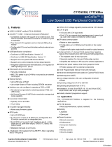
The Unified Development Platform (UDP) provides a development and demonstration platform for Silicon
Laboratories microcontrollers, short-range wireless devices, and software tools, including the Silicon Laboratories
Integrated Development Environment (IDE).
Figure 1. Unified Development Platform Block Diagram

C8051F850-DK-UG
2 Rev. 0.3
2. Relevant Documents
This document provides a hardware overview for the Unified Development Platform (UDP) system C8051F85x/86x
MCU card. Additional information on the UDP system and the Silicon Labs 8-bit MCUs can be found in the
documents listed in this section.
2.1. Motherboard User’s Guide
The UDP Motherboard User’s Guide contains information on the motherboard features and can be found at
www.silabs.com/udp.
2.2. Card User’s Guides
The UDP MCU, I/O, and radio test card user’s guides can be found at www.silabs.com/udp.
2.3. Application Notes
All 8-bit Application Notes can be found at www.silabs.com/8bit-appnotes.

C8051F850-DK-UG
Rev. 0.3 3
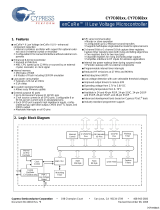
3. Hardware Setup
3.1. Using the MCU Card Alone
Refer to Figure 2 for a diagram of the hardware configuration when using the MCU card without a UDP
motherboard.
1. Connect the USB Debug Adapter to the 10-pin debug connector (J23) on the MCU card using the 10-pin
ribbon cable.
2. Connect the USB Debug Adapter to a USB Port on the PC.
3. Move the SW1 VDD Select switch to the top +3.3V_VREG position.
4. Verify that the JP2 Imeasure jumper is populated.
5. Power the MCU card through the power connector (J6) using the supplied 9 V ac/dc adapter.
Notes:
Use the Reset button in the IDE to reset the target when connected using a USB Debug Adapter.
Remove power from the MCU card and the USB Debug Adapter before connecting or disconnecting the
ribbon cable from the MCU card. Connecting or disconnecting the cable when the devices have power can
damage the device and/or the USB Debug Adapter.
Figure 2. Hardware Setup Using the MCU Card Alone
1
2
3
4
5

C8051F850-DK-UG
4 Rev. 0.3
3.2. Using the MCU Card with the UDP Motherboard
Refer to Figure 3 for a diagram of the hardware configuration when using the MCU card with a UDP motherboard.
1. Connect the MCU card to the UDP motherboard slot.
2. (Optional) Connect an I/O card to the UDP motherboard slot.
3. (Optional) Connect a radio test card to the radio test card slot in the UDP motherboard.
4. (Optional) Connect an EZLink card to the EZLink card slot in the UDP motherboard.
5. Connect the USB Debug Adapter to the 10-pin debug connector (J23) on the MCU card using the 10-pin
ribbon cable.
6. Connect the USB Debug Adapter to a USB Port on the PC.
7. Move the SW1 VDD Select switch to the lower MB position.
8. Verify that the JP2 Imeasure jumper is populated.
9. Connect the ac/dc power adapter to power jack J20 on the UDP motherboard. The board can also be
powered from the J16 USB, J1 mini USB connectors, or J11 battery connector socket.
10. Move the S3 power switch on the UDP motherboard to the ON position.
11. Update the motherboard firmware as described in Section 3.3.
Notes:
Use the Reset button in the IDE to reset the target when connected using a USB Debug Adapter.
Remove power from the target board and the USB Debug Adapter before connecting or disconnecting the
ribbon cable from the target board. Connecting or disconnecting the cable when the devices have power
can damage the device and/or the USB Debug Adapter.
The MCU card can be used alone without the motherboard. However, the motherboard must be powered if
an MCU card is connected.
Figure 3. Hardware Setup Using the Unified Development Platform
USB Debug
Adapter
Power
Adapter
(J20)
USB
Connector
(J16)
Power Select
Switch
Imeasure
Jumper
Virtual
COM Port

C8051F850-DK-UG
Rev. 0.3 5
3.3. Updating the UDP Motherboard Firmware
To ensure the UDP Motherboard supports the C8051F85x/86x MCU card, run the UDP Motherboard Firmware
Update Utility shown in Figure 4. This utility can be downloaded from www.silabs.com/udp.
1. Connect the UDP motherboard to a PC using a regular USB cable connected to the UDS connector (J16).
2. Run the utility.
3. Select the desired motherboard if more than one is connected to the PC.
4. Press the Update Selected Device button.
Figure 4. UDP Motherboard Firmware Update Utility

C8051F850-DK-UG
6 Rev. 0.3
4. Software Setup
Simplicity Studio greatly reduces development time and complexity with Silicon Labs EFM32 and 8051 MCU
products by providing a high-powered IDE, tools for hardware configuration, and links to helpful resources, all in
one place.
Once Simplicity Studio is installed, the application itself can be used to install additional software and
documentation components to aid in the development and evaluation process.
Figure 5. Simplicity Studio
The following Simplicity Studio components are required for the C8051F850 Development Kit:
8051 Products Part Support
Simplicity Developer Platform
Download and install Simplicity Studio from www.silabs.com/8bit-software or www.silabs.com/simplicity-studio.
Once installed, run Simplicity Studio by selecting Start
Silicon LabsSimplicity StudioSimplicity Studio
from the start menu or clicking the Simplicity Studio shortcut on the desktop. Follow the instructions to install the
software and click Simplicity IDE to launch the IDE.
The first time the project creation wizard runs, the Setup Environment wizard will guide the user through the
process of configuring the build tools and SDK selection.
In the Part Selection step of the wizard, select from the list of installed parts only the parts to use during
development. Choosing parts and families in this step affects the displayed or filtered parts in the later device
selection menus. Choose the C8051F85x family by checking the C8051F85x/86x check box. Modify the part
selection at any time by accessing the Part Management dialog from the Window
PreferencesSimplicity
Studio
Part Management menu item.
Simplicity Studio can detect if certain toolchains are not activated. If the Licensing Helper is displayed after
completing the Setup Environment wizard, follow the instructions to activate the toolchain.

C8051F850-DK-UG
Rev. 0.3 7
4.1. Running Blinky
Each project has its own source files, target configuration, SDK configuration, and build configurations such as the
Debug and Release build configurations. The IDE can be used to manage multiple projects in a collection called a
workspace. Workspace settings are applied globally to all projects within the workspace. This can include settings
such as key bindings, window preferences, and code style and formatting options. Project actions, such as build
and debug are context sensitive. For example, the user must select a project in the Project Explorer view in order
to build that project.
To create a project based on the Blinky example:
1. Click the Simplicity IDE tile from the Simplicity Studio home screen.
2. Click the Create new project link from the welcome screen or go to File
NewSilicon Labs MCU
Project.
3. In the Kit drop-down, select C8051F850 Development Kit, in the Part drop-down, select C8051F850, and
in the SDK drop-down, select the desired SDK. Click Next.
4. Select Example and click Next.
5. Under C8051F850 Development Kit in the Blinky folder, select F85x-86x Blinky and click Finish.
6. Click on the project in the Project Explorer and click Build, the hammer icon in the top bar. Alternatively,
go to Project
Build Project.
7. Click Debug to download the project to the hardware and start a debug session.
8. Press the Resume button to start the code running. The LED should blink.
9. Press the Suspend button to stop the code.
10. Press the Reset the device button to reset the target MCU.
11. Press the Disconnect button to return to the development perspective.
4.2. Simplicity Studio Help
Simplicity Studio includes detailed help information and device documentation within the tool. The help contains
descriptions for each dialog window. To view the documentation for a dialog, click the question mark icon in the
window:
This will open a pane specific to the dialog with additional details.
The documentation within the tool can also be viewed by going to Help
Help Contents or HelpSearch.

C8051F850-DK-UG
8 Rev. 0.3
4.3. Simplicity Configurator
The Simplicity Configurator is a configuration and code generation tool. This utility helps accelerate development
by automatically generating initialization source code to configure and enable the on-chip resources needed by
most design projects. In just a few steps, the wizard creates complete startup code for a specific Silicon Labs MCU.
To create a new Simplicity Configurator project:
1. Click the Create new project link from the welcome screen or go to File
NewSilicon Labs MCU
Project.
2. In the Kit drop-down, select C8051F850 Development Kit or None, in the Part drop-down, select
C8051F850, and in the SDK drop-down, select the desired SDK. Click Next.
3. Select Simplicity Configurator Program and click Next.
4. Fill in the Project name and select the desired device. The C8051F850-C-GU-QSOP device is on the
C8051F850 Target Board. Click Finish.
The Simplicity Configurator project displays properties for each peripheral. To configure a peripheral, click on the
DefaultMode Peripherals tab at the bottom and click on a peripheral. Checking the box for a peripheral will add it
to code generation. Once a peripheral is selected, configure the registers using the Properties view. Select a new
value for a property with either an input box or a drop-down menu and press Enter to set it.
Figure 6. Simplicity Configurator – Configuring Peripheral Properties

C8051F850-DK-UG
Rev. 0.3 9
To configure pins, click on the DefaultMode Port I/O tab at the bottom of main window. Clicking on a pin brings up
a property window for the pin. Clicking anywhere else in the main window opens a property window for the
crossbar. Select multiple pins with Ctrl + left click or mouse dragging over the desired set of pins. The package
diagram displays the configured peripherals on the pins, including non-crossbar signals (i.e. ADC inputs).
Code generation updates every time the configuration project saves. After configuring the device, add any non-
initialization code, build, and debug the same as with any other project.
More information on Simplicity Configurator can be found in AN0823: Simplicity Configurator User’s Guide and
AN0821: Simplicity Studio C8051F85x Walkthrough. Application notes can be found on www.silabs.com/8bit-
appnotes.
Figure 7. Simplicity Configurator – Configuring Port I/O

C8051F850-DK-UG
10 Rev. 0.3
4.4. Legacy 8-bit IDE
Note: Using the Simplicity Studio tools with the C8051F850 Development Kit is recommended. See section 4. "Software
Setup‚" on page 6 for more information.
Download the 8-bit software from the website (www.silabs.com/8bit-software) or use the provided installer on the
CD-ROM to install the software tools for the C8051F85x/86x devices. After installation, examples can be found in
...\Examples\C8051F85x_86x in the installation directory. At a minimum, the C8051F850 DK requires:
Silicon Labs IDE—Software enabling initial evaluation, development, and debugging.
Configuration Wizard 2—Initialization code generation software for the C8051F85x/86x devices.
Keil C51 Tools—Keil 8051 Compiler/Assembler/Linker toolchain.
CP210x Drivers—Virtual COM Port (VCP) drivers for the CP210x COM interface. More information on this
installation process can be found in Section 4.5.
Other software available includes:
Keil µVision Driver—Driver for the Keil µVision IDE that enables development and debugging on
C8051Fxxx MCUs.
Flash Programming Utilities and MCU Production Programmer—Programming utilities for the
production line. More information on the available programming options can be found on the website:
http://www.silabs.com/products/mcu/Pages/ProgrammingOptions.aspx.
ToolStick Development Tools—Software and examples for the ToolStick development platform. More
information on this platform can be found at www.silabs.com/toolstick.
The development kit includes the latest version of the C51 Keil 8051 toolset. This toolset is initially limited to a code
size of 2 kB and programs start at code address 0x0800. After registration, the code size limit is removed entirely
and programs will start at code address 0x0000.
To register the Keil toolset:
1. Find the Product Serial Number printed on the CD-ROM. If you no longer have this serial number,
register on the Silicon Labs website (www.silabs.com/8bit-software) to obtain the serial number.
2. Open the Keil µVision4 IDE from the installation directory with administrative privileges.
3. Select File
License Management to open the License Management window.
Figure 8. Keil µVision4 IDE License Management Window
4. Click on the Get LIC via Internet... button to open the Obtaining a License IDE Code (LIC) window.
5. Press OK to open a browser window to the Keil website. If the window doesn’t open, navigate to

C8051F850-DK-UG
Rev. 0.3 11
www.keil.com/license/install.htm.
6. Enter the Silicon Labs Product Serial Number printed on the CD-ROM, along with any additional required
information.
7. Once the form is complete, click the Submit button. An email will be sent to the provided email address
with the license activation code.
8. Copy the License ID Code (LIC) from the email.
9. Paste the LIC into the New License ID Code (LIC) text box at the bottom of the License Management
window in µVision4.
10. Press the Add LIC button. The window should now list the PK51 Prof. Developers Kit for Silabs as a
licensed product.
11. Click the Close button.
4.5. CP210x USB to UART VCP Driver Installation
The MCU Card includes a Silicon Labs CP210x USB-to-UART Bridge Controller. Device drivers for the CP210x
need to be installed before the PC software can communicate with the MCU through the UART interface. Use the
drivers included CD-ROM or download the latest drivers from the website (www.silabs.com/interface-software).
1. If using the CD-ROM, the CP210x Drivers option will launch the appropriate driver installer. If downloading
the driver package from the website, unzip the files to a location and run the appropriate installer for the
system (x86 or x64).
2. Accept the license agreement and follow the steps to install the driver on the system. The installer will let
you know when your system is up to date. The driver files included in this installation have been certified by
Microsoft.
3. To complete the installation process, connect the included USB cable between the host computer and the
COM PORT USB connector (J5) on the MCU Card. Windows will automatically finish the driver installation.
Information windows will pop up from the taskbar to show the installation progress.
If needed, the driver files can be uninstalled by selecting Windows Driver Package—Silicon
Laboratories... option in the Programs and Features window.

C8051F850-DK-UG
12 Rev. 0.3
5. C8051F85x/86x MCU Card Overview
The C8051F850 MCU card enables application development on the C8051F85x/86x MCU device family. The card
connects to the MCU card expansion slot on the UDP motherboard and provides complete access to the MCU
resources. Each expansion board has a unique ID that can be read out of an EEPROM or MCU on the board,
which enables software tools to recognize the connected hardware and automatically select the appropriate
firmware image. The target MCU card can also be detached from the UDP and used alone as a development or
demonstration tool.
Figure 9 and Figure 10 highlight the C8051F850 MCU card features.
Figure 9. C8051F850 MCU Card Features—Front
Potentiometer
Analog
Terminals
Push-Button
Switches
Mini-B USB
Connector
for VCP
Power
Debug Connector
Prototyping Area
Reset Push-Button
LEDs
VCP-Enabled LED
VDD Select Switch
and Power LED
Current Measure Jumper
Port Access
Voltage and Ground
Reference Access

C8051F850-DK-UG
Rev. 0.3 13
Figure 10. C8051F850 MCU Card Features—Back
Electronic Board ID
(EBID)
Virtual COM Port
Port Pin Isolation
Resistors

C8051F850-DK-UG
14 Rev. 0.3
5.1. Push-Button Switches and LEDs (S1-2, DS5-6)
The UDP C8051F850 MCU Card has two push-button switches and two LEDs. The two LEDs connect to P1.0 and
P1.1, and the two switches connect to P1.7 and P2.1. The switches are normally open and pull the pin voltage to
ground when pressed. The LEDs connect to VDD through a current-limiting resistor and turn on when the
corresponding port pin is low.
The header J27 can be used to disconnect the switches and LEDs from the GPIO pins.
5.2. Analog Terminals (J34)
Several of the C8051F850 port pins used for analog functions are connected to the J34 terminal block. Refer to
Table 2 for the J34 terminal block connections.
5.3. Potentiometer (R13)
The potentiometer is available on P1.2 (ADC0.10). To use the potentiometer, install a shorting block on J27 pins 9
and 10 to connect P1.2 to the potentiometer.
5.4. Voltage and Ground Reference (J32)
The C8051F850 has options to use an external voltage reference on the P0.0 / VREF pin and an external analog
ground reference on the P0.1 / AGND pin. The J32 header allows an external supply to clip to pin 1 for AGND and
pin 2 for VREF. These signals can then be connected to the MCU by populating a shorting block between pins 3
and 5 for AGND and pins 4 and 6 for VREF. Populating this shorting block for VREF connects P0.0 to the required
capacitors for the external reference.
Table 1. Switch and LED Pin Descriptions
MCU Pin Function
PB1.0 Red LED DS5 (LED1)
PB1.1 Red LED DS6 (LED2)
PB1.7 Switch S1
PB2.1 Switch S2
Table 2. Terminal Block Pin Descriptions (J34)
Terminal Pin MCU I/O
1 VREF / P0.0
2GND
3 ADC0.9 / P1.1
4 ADC0.12 / P1.4
5 ADC0.10 / P1.2
6 ADC0.13 / P1.5
Table 3. Terminal Block Pin Descriptions (J25)
MCU Pin Analog Signal Description
P0.0 VREF Clip external source to J32 pin 2, apply shorting block
between pins 4 and 6 to connect to the MCU
P0.1 AGND Clip external ground to J32 pin 1, apply shorting block
between pins 3 and 5 to connect to the MCU

C8051F850-DK-UG
Rev. 0.3 15
5.5. VDD Power Select Switch (SW1)
The VDD power supply has two power options: UDP motherboard (PWR_VDD_OUT) and on-board +3.3 V
regulator power. The VDD Power Select switch is used to select between the two options. The +3.3 V regulator
power option is the upper +3.3_VREG position and allows the board to be powered from a diode-OR of four power
sources: 9 V Power Adapter (J6), the USB connector labeled COM PORT (J5), the USB Debug Adapter (J23), or
from the UDP motherboard bulk supply (PWR_5.0V_BULK).
5.6. Power LED (DS9)
The blue power LED provides visual feedback when the board is powered through USB, the 9 V power adapter, the
USB Debug Adapter, or from the UDP motherboard. The power LED indicates that power is available on the board
and the VDD Power Select switch must be configured properly to power the MCU.
5.7. Imeasure Jumper (JP2)
The Imeasure jumper (JP2) allows for easy access to measure the VDD current of the MCU. The shorting block for
this header is populated by default, and the direction of current is shown with a silk screen arrow. To measure the
supply current, remove the corresponding shorting block and connect a current measurement device across the
unpopulated header.
The voltage supply prior to the Imeasure jumper is the VDD pre-measure (VDD_PM) net, which supplies all of the
external LEDs, switches, USB COM, and reset pull-up. The VDD after the Imeasure jumper only connects to the
MCU.
5.8. Debug Header (J23)
The shrouded 10-pin debug header supports the Silicon Labs USB Debug Adapter. This connector provides a C2
debug connection to the C8051F85x/86x on the MCU card.
5.9. Reset Button (S5)
The reset push-button switch is just below the debug header (J23). Pushing this button will always reset the MCU.
Note that pushing this button while the IDE is connected to the MCU will result in the IDE disconnecting from the
target.
5.10. UART Connection Options (J7, U2, U4, U5)
The MCU card features a USB virtual COM port (VCP) UART connection via the mini-B USB connector (J5)
labeled COM PORT. The VCP connection uses the CP210x USB-to-UART bridge chip (U2). The GPIO pins
connected to the CP210x device can be enabled or disabled through the J7 header. Table 4 shows the GPIO pins
that are routed to the CP210x.
In addition to the CP210x USB-to-UART connection, the MCU card can connect the C8051F850 UART signals
with the UDP Motherboard UART signals UART_TX_SYS and UART_RX_SYS using U5. The signals to switch
between the two interfaces are UART_VCP_EN and UART_SYS_EN and are controlled by the motherboard. The
default selection with or without the motherboard is the CP210x VCP interface using a pull-down resistor R20.
5.11. Port Pin Headers (J24, J24, J26)
All of the MCU port pins are available on the 0.100-inch headers on MCU card. Each connector provides
connections to each port, VDD, and ground. Any unused pins on the P2 header are not connected. Some of these
port pins are shared with other functions on the board and may be modified as explained in Section 5.13.
Table 4. CP210x Controlled GPIO Pins
MCU Pin COM Function
P0.4 UART Transmit
P0.5 UART Receive
VDD COM VIO

C8051F850-DK-UG
16 Rev. 0.3
5.12. Electronic Board ID (EBID) (U1, J35)
The MCU card has a unique ID that can be read out from the Silicon Labs C8051F990 MCU (U1). This MCU
enables software tools to recognize the connected hardware and automatically select the appropriate firmware
image.
The EBID device uses two I
2
C signals to communicate: UDPBUS_SDA_A and UDPBUS_SCL_A. These signals
are connected to P0.6 and P0.7 on the C8051F850 MCU through the J25 header. These signals can be
disconnected from the MCU during power measurements.
5.13. MCU Port Pin Connections
The MCU card has many UDP connections for use with different I/O cards and the UDP motherboard. Table 6
describes all functions connected to each pin on the C8051F850 MCU. All of the UDP connections are made with
populated 0 ohm resistors on the back of the MCU card. To disconnect a signal from the pin, remove the 0
resistor.
Table 5. Terminal Block Pin Descriptions (J25)
MCU Pin EBID / UDP Signal
P0.6 UDPBUS_SDA_A
P0.7 UDPBUS_SCL_A
Table 6. MCU Card and UDP Pin Functions
MCU Pin MCU Card Function or UDP Signal
P0.0 VREF SPI_SCK_EZR ADC_VREF GPIO05
P0.1 AGND SPI_MISO_EZR ADC_VREFGND GPIO06 EPCA_CH1_MOTOR
P0.2
EXT_INT0 SPI_MOSI_EZR CP_POS_A
P0.3 EXT_INT1 SPI_NSS0_EZR CP_NEG_A
P0.4 UART_TX_SYS UART_TX_A
P0.5 UART_RX_SYS UART_RX_A WAKEUP0
P0.6 UDPBUS_SDA_A UART_RTS_SYS UART_RTS_A I2C_SDA_EZR EPCA_CH3_MOTOR
P0.7 UDPBUS_SCL_A UART_CTS_SYS UART_CTS_A I2C_SCL_EZR EPCA_CH5_MOTOR
P1.0 LED1 ADC_IN0 CP_OUT_A
P1.1 LED2 ADC0.9 ADC_IN1 CP_OUTA_A
P1.2 Potentiometer ADC0.10 ADC_IN2 CLKOUT0
P1.3 PCA_CH0_A ADC_IN3
P1.4 ADC0.12 PCA_CH1_A GPIO02 EPCA_CH0_MOTOR
P1.5 ADC0.13 PCA_CH0_B WAKEUP1 GPIO03 EPCA_CH2_MOTOR
P1.6
PCA_ECI_A TIMER_CT_A GPIO04 EPCA_CH4_MOTOR
P1.7 Switch S1 TIMER_CT_B
GPIO01
P2.0 C2D
P2.1 Switch S2 GPIO00

C8051F850-DK-UG
Rev. 0.3 17
6. Using the C8051F850 MCU Card with the UDP Motherboard
6.1. MCU Card Header Connections
The MCU card has four connectors with 100 pins each. These 400 pins are directly tied to the UDP motherboard
and I/O cards. These signals are named and designed to support a wide variety of features and applications, and
the C8051F850 MCU card implements a subset of these connections.
The MCU cards and I/O cards are designed so that a maximum number of functions are shared between each
card. This allows a particular type of I/O card to be shared amongst all MCU cards that connect to the same
signals.
The MCU card slot includes the following components:
J1 MCU card connector H1
J2 MCU card connector H2
J3 MCU card connector H3
J4 MCU card connector H4
The C8051F850 MCU card implements the signals described in Table 8, Table 9, Table 10, and Table 11 in the
Appendix.
6.2. Shorting Blocks: Factory Defaults
The C8051F850 MCU card comes from the factory with pre-installed shorting blocks on several headers. Figure 11
shows the positions of the factory default shorting blocks.
Figure 11. Shorting Blocks: Factory Defaults
A shorting block is installed across the JP2 Imeasure header to enable power to the MCU. Shorting blocks are
installed on J7 to enable the virtual COM port. Shorting blocks are also installed on J27 to enable the switches,
LEDs, and potentiometer to be connected to GPIO pins.

C8051F850-DK-UG
18 Rev. 0.3
7. Power Measurement
The C8051F850 MCU card includes a JP2 Imeasure jumper for MCU power measurement purposes. The VDD
supply on pin 2 of the header connects only to the MCU on the board. The VDD pre-measure (VDD_PM) supply on
pin 1 of the JP2 header powers the external LEDs, switches, reset switch, potentiometer, and VCP COM.
7.1. Measuring Power with Fixed VDD
To measure the power of the C8051F850 MCU using the MCU card at a fixed 3.3 V:
1. Connect a USB Debug Adapter to the 10-pin shrouded debug connector (J23).
2. Remove the three shorting blocks from J7.
3. Remove the JP2 Imeasure shorting block.
4. Connect a multimeter across (positive side on the left pin, current flow indicated by the silk screen arrow).
5. Move the VDD Select switch (SW2) to the upper +3.3V_VREG position.
6. Connect the 9 V power adapter to POWER (J6).
7. Download the code to the board.
8. Remove the debug adapter connection.
9. Measure the power of the device.
Figure 12. C8051F850 MCU Card Power Measurement Configuration— Fixed VDD
+000.500
µADC
USB Debug
Adapter
1
2
3
5
8
4
6

C8051F850-DK-UG
Rev. 0.3 19
7.2. Measuring Power with Varying VDD
To measure power with a varying VDD:
1. Connect a USB Debug Adapter to the 10-pin shrouded debug connector (J23).
2. Remove the three shorting blocks from J7.
3. Remove the JP2 Imeasure shorting block.
4. Connect a multimeter across the JP2 Imeasure jumper (positive side on the left pin, current flow indicated
by the silk screen arrow).
5. Move the VDD Select switch (SW2) to the lower MB position.
6. Connect the negative terminal of a bench power supply to board ground.
7. Connect the positive terminal of a bench power supply to the positive side (left pin) of the Imeasure
jumper. This will ensure that the /RST pin pull-up is powered.
Note: The pull-up resistor on /RST is powered by the VDD pre-measure (VDD_PM) net, which is separated from the VDD net
with the Imeasure shorting block (JP2) removed. Powering the MCU using VDD without powering the VDD_PM net will
prevent the IDE from communicating with the MCU.
8. Download the code to the board.
9. Remove the debug adapter connection.
10. Measure the power of the device.
Figure 13. C8051F850 MCU Card Power Measurement Configuration—Varying VDD
8. Known Board Issues
There are no known issues with Revision 200 of the C8051F850 MCU card.
+000.500
µADC
2.8
V
USB Debug
Adapter
1
2
3
5
9
6
4
7

C8051F850-DK-UG
20 Rev. 0.3
9. Schematics
5 4 3 2 1
Debug Interface
Port Access
UDP Configuration
VDD_PM
VDD
DEBUG_5.0V
VDD_PM VDD_PM
P0.0
P0.2
P0.4
P0.6
P0.1
P0.3
P0.5
P0.7
P0.2
P0.1
P0.0
C2CK
P0.5
P0.3
P0.4
P0.6
P0.7
P1.0
P1.1
P1.2
P1.3
P1.4
P0.0
P0.1
C2D
P1.7
P1.6
P1.5
P2.1
C2CK
/RST
C2D
P2.0
P1.0
P1.2
P1.4
P1.6
P1.1
P1.3
P1.5
P1.7
P2.0 P2.1
GPIO05
SPI_SCK_EZR
ADC_VREF
GPIO06
SPI_MISO_EZR
ADC_VREFGND
SPI_MOSI_EZR
EXT_INT0
P0.2
SPI_NSS0_EZR
EXT_INT1
P0.3
UART_TX_AP0.4
UART_RX_AP0.5
WAKEUP0
P0.6
P0.7
ADC_IN0
CP_OUT_A
P1.0
ADC_IN1
CP_OUTA_A
P1.1
ADC_IN2
CLKOUT0
P1.2
PCA_CH0_A
ADC_IN3
P1.3
PCA_CH1_AP1.4
GPIO02
PCA_CH0_BP1.5
GPIO03
PCA_ECI_AP1.6
TIMER_CT_A
GPIO04
P1.7 TIMER_CT_B
GPIO01
P2.1 GPIO00
WAKEUP1
UART_RTS_A
UART_RTS_SYS
I2C_SDA_EZR
UART_CTS_A
UART_CTS_SYS
I2C_SCL_EZR
CP_POS_A
CP_NEG_A
EPCA_CH0_MOTOR
EPCA_CH2_MOTOR
EPCA_CH4_MOTOR
EPCA_CH1_MOTOR
EPCA_CH5_MOTOR
UDPBUS_SDA_A
EPCA_CH3_MOTOR
UDPBUS_SCL_A
400 W Cesar Chavez
Austin, TX 78701
400 W Cesar Chavez
Austin, TX 78701
400 W Cesar Chavez
Austin, TX 78701
MH
R86 0
R121 0
R75 0
R83 0
R114 0
R106 0
R89 0
R99 0
R112 0
R111 0
R79 0
R71 0
J24
Port 0
1
1
2
2
3
3
4
4
5
5
6
6
7
7
8
8
9
9
10
10
TP15
C2CK
R116 0
JS12Jumper Shunt
R115 0
R117 0
R68 0
R98 0
TP14
C2D
R107 0
J23
5X2 Shrouded Header
DEBUG
1
1
2
2
3
3
4
4
5
5
6
6
7
7
8
8
9
9
10
10
JS13Jumper Shunt
R113 0
R119 0
R77 0
R80 0
R102 0
R87 0
R64
1K
C28
0.1uF
J26
Port 2
1
1
2
2
3
3
4
4
5
5
6
6
7
7
8
8
9
9
10
10
R84 0
R90 0
R81 0
R96 0
R85 0
R76 0
R36 0
C30
1uF
R88 0
U11
C8051F850
NC
1
P0.2
2
P0.1 / AGND
3
P0.0 / VREF
4
GND
5
VDD
6
/RST / C2CK
7
C2D / P2.0
8
P1.7
9
P1.6
10
P1.5
11
P2.1
12
NC
13
P1.4
14
P1.3
15
P1.2
16
P1.1
17
P1.0
18
P0.7
19
P0.6
20
P0.5
21
P0.4
22
P0.3
23
NC
24
R72 0
MH
R66 0
R103 0
J25
Port 1
1
1
2
2
3
3
4
4
5
5
6
6
7
7
8
8
9
9
10
10
R101 0
R109 0
R110 0
MH
R65 0
R70 0
R78 0
R63
1K
J35
EBID I2C
1
1
3
3
2
2
4
4
R91 0
R37 0
MH
R73 0
R67 0
R104 0
Figure 14. C8051F850 UDP MCU Card Schematic (Revision 200) (1 of 5)
/