Page is loading ...

3421
3421
B
A
D
B
A
D
C
REVISION HISTORY
ZONE REV DESCRIPTION BY/DATE APPROVED/DATE
E.C.O.
SIZE CAGE CODE DWG NO. REV
TITLE
PROJ. NO.
This drawing and all copies and the design and data shown are the property of HARDIGG
INDUSTRIES , INC. So. Deerfield, MA U.S.A. and include proprietary information. The
borrower by receipt or retention of the drawing agrees that, except as expressly
authorized in writing by HARDIGG INDUSTRIES, INC. it will (1) not use the drawing or any
copy of the design or data shown (2) not reproduce, copy, excerpt, exhibit or distribute
the drawing or any copy for use by others and (3) upon demand return the drawing, all
copies and all material copies therefrom.
CHKD. APVD.
ENGR. DR.
TOLERANCE
NEXT ASSY. SCALE
C 11214
CUST:
UNIT:
CONTRACT NO.
.XX .XXX ANGLE
UNLESS OTHERWISE
SPECIFIED DATE DATE
DATE DATE
± ± ±
DWG NO SH REV
DWG NO SH REV
COMPUTER CONTROLLED DOCUMENT
MANUAL CHANGES NOT ALLOWED
± HARDIGG® INDUSTRIES, INC.
South Deerfield, Massachusetts
01373 USA
dft Template Rev 30MAR06
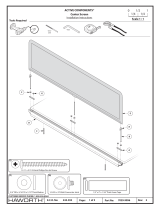
IM BEZEL KIT INSTALLATION INSTRUCTIONS
P111-0332
DAN GILMORE 07/23/08
B
P111
CHRIS GHIZ 08/07/08 SPRAGUE 08/07/08
SHEET 1 OF 4
SHT 2 A ADD RTV SILICONE NOTE TO "REAR" VIEW D. GALE 9/5/08040203
REPLACED LOGO ON SHEETS 2-4040830
BC.GHIZ
09JAN26
C. GHIZ 9/5/08
B
NOTES:
1. MATERIAL: 20LB BOND PAPER, COLOR WHITE
2. SEE SHEET 2 FOR ART WORK.
3. PRINT ON BOTH SIDES OF SHEET AS SHOWN.
4. THIS PART AND ALL ITS COMPONENTS MUST COMPLY WITH THE
EUROPEAN PARLIAMENT DIRECTIVE 2002/95/EC ON THE
RESTRICTION OF THE USE OF CERTAIN HAZARDOUS SUBSTANCES
(ROHS). THE PART (INCLUDING PLATING), MUST NOT CONTAIN ANY
OF THE FOLLOWING SUBSTANCES: LEAD, MERCURY, CADMIUM,
HEXAVALENT CHROMIUM, POLY BROMINATED BIPHENYLS (PBB) OR
POLYBROMINATED DIPHENYL ESTERS (PBDE).
Sean Cassidy
2009.01.26 17:35:24
-05'00'

4 3
34
B
A
D
C
1
1
B
A
D
2
2
SIZE CAGE CODE DWG NO. REV
SCALE
C 11214
DWG NO SH REV
COMPUTER CONTROLLED DOCUMENT
MANUAL CHANGES NOT ALLOWED
P111-0332
SHEET 2 OF 4
B
B
FRONT REAR
11.0
8.5

P111-0332RevB Rev A 1/26/2009rr
BASE BEZEL KIT OPTION
INSTALLATION INSTRUCTIONS
Assemble the bezel by sliding the
corner pieces into the ends of the
rail. (Figure 1)
Set the bezel frame into the case as
shown. (Figure 2)
Use small blocks (removed after
installation) or clamps to hold the
frame at the desired height. Be sure
not to block any of the rivet holes.
Note: Height is dependent upon
your application. Reference bezel
plate template drawing for
dimensional instructions.
Adjust the rails and corner pieces so
that all pieces fit snugly against the
interior sides of the case. A gap
between the mating surfaces of the
corner pieces and rails is normal,
and will vary depending on the
depth the bezel frame is installed.
For each rail, ensure gaps between it
and corner pieces are equal. This
ensures that each rail is properly
centered within the case, ensuring
that your bezel plate will install
properly.
Using the rivet holes in the frame as
a guide, drill holes through the case
wall from the inside, using a right-
angle drill with a #11 (.191)
(English Kit) or M4.9 (Metric Kit)
drill bit.
*Note: For IM20XX bezel kit
installations only, drill rear side rail
holes. Drill the front left and right
side holes through the case shell and
bezel plastic corner piece from the
outside. (Figure 2)
Assemble the rivets and watertight
washers. Be sure that the washer
goes over the large end of the rivet,
with the rubber surface facing away
from the thin, mandrel end of the
rivet. For the side holes closest to
the front of the case on sizes
IM20XX denoted as * use the
metal washer provided as a back up
plate for installing the rivet through
the plastic corner piece.
Push rivets and watertight washers
into the case as shown. (Figure 3)
Be sure that the rubber surface of
the watertight washer is against the
outside of the case.
Use a standard rivet gun to fasten
the rivets and washers to the case.
Remove blocks and/or clamps.
Place gasket into the groove along
the top of the bezel frame.
Assemble the plate to the bezel
frame using #10-32 threaded screws
(English Kit) or 4mm metric screw
(Metric Kit).
*
*
*
*
METAL
WASHER
Base Installation
Hardigg Cases
147 North Main Street, South Deerfield, MA 01373
www.StormCase.com
1 (413) 665-2163

P111-0332RevB Rev - 1/26/2009rr
LID BEZEL KIT OPTION
INSTALLATION INSTRUCTIONS
Assemble the bezel by sliding the
corner pieces into the ends of the
rail. (Figure 1)
Set the bezel frame into the case as
shown. (Figure 2)
Use small blocks (that can be
removed after installation) or
clamps to hold the frame at the
desired height. Be sure not to block
any of the rivet holes. Note: Height
is dependent upon your application.
Reference bezel plate template
drawing for dimensional
instructions.
Adjust the rails and corner pieces so
that all pieces fit snugly against the
interior sides of the case. A gap
between the mating surfaces of the
corner pieces and rails is normal,
and will vary depending on the
depth the bezel frame is installed.
For each rail, ensure gaps between it
and corner pieces are equal. This
ensures that each rail is properly
centered within the case, ensuring
that your bezel plate will install
properly.
Using the rivet holes in the frame as
a guide, drill holes through the case
wall from the inside, using a right-
angle drill with a #11 (.191)
(English Kit) or M4.9 (Metric Kit)
drill bit.
Assemble the rivets and watertight
washers. Be sure that the watertight
washer goes over the large end of
the rivet, with the rubber surface
facing away from the thin, mandrel
end of the rivet.
Push rivets and watertight washers
into the case as shown. (Figure 3)
Be sure that the rubber surface of
the watertight washer is against the
outside of the case.
Use a standard rivet gun to fasten
the rivets and washers to the case.
Remove blocks and/or clamps.
Place gasket into the groove along
the top of the bezel frame.
Gasket may require a small amount
of RTV Silicone (commercially
available) to conform and hold
gasket to lid profile, paying close
attention to rib areas.
Assemble the plate to the bezel
frame using #10-32 threaded screws
(English Kit) or 4mm metric screw.
(Metric Kit)
Lid Installation
Hardigg Cases
147 North Main Street, South Deerfield, MA 01373
www.StormCase.com
1 (413) 665-2163
/


