Page is loading ...

1
The Mini Pinni Quilting Frame
Copyright September 2007
Jim M. Bagley, GraceWood, Inc
(Reproduction Prohibited)
Print Date 10-16-07

2
3
4
5
6
6
6
7
8
8
8
9
9
9
10
10
11
11
11
12
12
13
13
14
14
15
15
16
16
17
17
18
19
Part List
Parts List A ………………………………………………....…....…………....…...........
Parts List B and Hardware List…………………….…....…………....…....................
Manufacturer Information…………………………………....…...…………....…........
Assembly Steps
Step 1: Outer Leg Sub-Assembly ………………………...…....…………....….........
Step 2: Middle Leg Assembly …………………………….…....…………....…..........
Step 3: Frame End Sub-Assembly………………………..…....…………....….........
Step 4: Queen Table Assembly…………………………………..…....…………........
Step 5: Queen Table Supports & Table Surface Attachment………………………..
Step 6: Queen Track Attachment……………………………….....…....….................
Step 7: Queen Rail Assembly……………………………….....…....…......................
Step 8: Rail Mount End Assembly……………………………….....…....…...............
Step 9: Rail Attachment to Table Assembly……………..…....…………....…...........
Step 10: Top Plate Assembly……………………………..…....…………....….............
Step 11: Bottom Plate Assembly………………………....…....…………....…...........
Step 12: Bottom Plate Placement………………………...…....…………....…..........
Step 13: Top Plate Placement…………………………....…....…………....…...........
Step 14: Sewing Machine Placement…………………....…....…………....…...........
Step 15: Leveling the Table…………………………….....…....…………....…...........
Step 16: Crib Table & Frame End Assembly………………………….....…....………
Step 17: Crib Table Support & Table Surface Attachment……..…....…………....…
Step 18: Crib Track Attachment…………………………….....…....…………....…....
Step 19: Crib Rail Assembly………………………….....…....…………....….............
Fabric Installation……………………………………………....…………....…...........
Step 1: Quilt Top to the Quilt Top Rail…....…....…....…....…..…………....…............
Step 2: Backing to Backing Rail …....…....…....…....…....…...…………....…...........
Step 3: Attach Quilt Layers to Take-Up Rail …....…....…....……………....…...........
Rolling Fabric…………………………………………………...…………....…............
Turning Quilt Around…………………………………………...…………....…...........
Making Cloth Leaders………………………………………....…………....…............
Bungee Clamp Installation…………………………………....…………....…...........
Speed Control……………………………………………...…....…………....…...........
Sewing Tips………………………………………………...…....…………....…...........
The Mini Pinni Quilting Frame
By The Grace Company

3
(2) Queen Track Support
(3) Queen Aluminum Rail
Parts List A
(3) Crib Aluminum Rail
(2) Crib Track Support
(1) Left Frame End
(1) Right Frame End
(4) Table Support
(3) Rail Coupler(2) Joint Splice
(3) Middle Leg Brace(4) Top Leg Brace
(6) Leg
(6) Leveling Foot
(2) Take-Up
Rail Fixture
(1) Right Frame
Corner
(1) Left Frame
Corner
(2) Queen Plastic Track
(2) Crib Plastic Track
(3) Fabri-fast Tubing
(1) Right Front Rail
Mount End
Pre-Installed (1) Fixture
(1) Left Front Rail
Mount End
Pre-Installed (1) Fixture
(6) Ratchet
Wheel
(1) Left Take-Up
Rail Mount End
(1) Right Take-Up
Rail Mount End

4
(1) Bottom Plate Platform
(4) Bungee Clamp
(1) Fabri-Fast Tool (1) Speed Control Assembly
Parts List B
(1) Top Plate
Pre-Installed (4) Wheels
(1) Bottom Plate
Pre-Installed (4) Wheels
(1) Handle Brace (1) Right Handle Tube
Pre-Installed (2) Grip Foam
(1) Left Handle Tube
Pre-Installed (2) Grip Foam
(4) Sewing Machine
Clamp Assembly
(2) Bottom Plate Extrusion
End Cap A
(2) Bottom Plate Extrusion
End Cap B
(6) Plastic Knob (6) 6mm Hex Nut
(2) 6mm X 40mm SHBC
(Socket Head Button Screw)
(76) 6mm X 10mm SHBC
(Socket Head Button Screw)
(44) 5mm X 10mm SHBC
(Socket Head Button Screw)
(6) 6mm X 35mm Hex Screw
(4) 6mm X 12mm SHBC
(Socket Head Button Screw)
(18) 5mm X 16mm SHBC
(Socket Head Button Screw)
Hardware List
Tools Needed:
Open end wrench (Provided)
3mm, and 4mm Allen wrenches (provided)
Fabri-Fast Tool (to be used when installing your fabric)

5
Innovation and Evolution
Grace Quilting Systems have been
developed over the past two decades
with several original design innovations.
Additionally, because of feedback from
many of the thousands of quilters who
have purchased and use our machine
quilting systems, we have been able to
make a frame that will truly enhance the
entire process of machine quilting from
beginning to end.
WELCOME!
A
s you begin assembly of your new home machine quilting system, keep in the mind the following:
1: The assembly process will be simple and step-by-step.
2: Read through each step completely before beginning that step.
3: Using the parts list as a reference, take the parts out of the box and make sure that you have them all.
4: Identify Hardware Packets: All hardware is separated by type and each packet is labeled for ease in identification.
Grace Quilting Frames and Hoops

6
Step 1: Outer Leg Sub-Assembly
Parts Needed:
4- Legs
4- Leveling Feet
2- Top Leg Braces
2- Middle Leg Braces
16- 6mm X 10mm SBHC Screws
Tools Required:
4mm Allen Wrench
1-1: Screw a Leveling Foot into the bottom of each of the legs as
shown in Fig (1-1).
***Do not tighten the screws till you have completed step 1.***
1-2: Lay the two Leg Assemblies down to simplify this step. Make sure
the four holes on the face of the Legs are to the outside and secure
the Middle Leg Brace on the middle of the leg with four (4)
6mmX10mm SBHC Screws.
1-3: Secure the Top Leg Brace on the top of the leg with four (4) 6mm
X10mm SBHC Screws. Tighten the 6mm X 10mm SBHC Screws using
the 4mm Allen Wrench to secure them in place.
1-4: Repeat the first three steps to complete a total of two (2) Outer
Leg Assemblies as shown in Fig (1-2).
Step 2: Middle Leg Assembly (Queen Only)
Parts Needed:
2- Legs
2- Leveling Feet
2- Top Leg Braces
1- Middle Leg Braces
12- 6mm X 10mm SBHC Screws
Tools Required:
4mm Allen Wrench
2-1: Repeat steps 1-2 & 1-3 of the Outer Leg Assembly as shown in
Fig (1-2).
2-2: Secure the two Top Leg Braces on the top of the legs with eight
(8) 6mm X10mm SBHC Screws. Make sure the two folds on the Top
Leg Braces are to the inside as shown in fig (2-1).
Step 3: Frame End Sub-Assembly
Parts Needed:
2- Take-Up Rail Fixtures
1- Right Frame End
1- Left Frame End
2- Plastic Knobs
6- 6mm X 35mm Hex Screws
Fig (1-2)
Fig (1-1)
Fig (2-1)

7
Slide Down
3-1: Put the two (2) 6mm X 35mm Hex screws into the Take-Up Rail
Fixture as shown in Fig (3-1). Make sure the hex heads are
seated into the countersinks on the Take-Up Rail Fixture.
3-2: Slide the Take-Up Rail Fixture down to the middle of the
slot in the Frame End as shown in Fig (3-2).
3-3: Slide an additional 6mm X 35mm Hex Screw into the Take-Up
Rail Fixture as shown in Fig (3-2) and secure with the Plastic Knob.
3-4: Repeat step (3-1) to (3-3) to complete the other Frame End.
Step 4: Queen Frame Assembly, turn to Step 15,
on Page 12 to assembly your frame in Crib Size
Fig (3-1)
Fig (3-2)
Fig (4-1)
Fig (4-2)Fig (4-3)
Fig (3-3)
Parts Needed:
2- Outer Leg Assemblies
1- Middle Leg Assembly
2- Crib Track Supports
2- Queen Track Supports
1- Right Frame End Sub-Assembly
1- Left Frame End Sub-Assembly
1- Right Frame Corner
1- Left Frame Corner
2- Joint Splices
36- 6mm X 10mm SBHC Screws
4- 6mm X 12mm SBHC Screws
Tools Required:
4mm Allen Wrench
We recommend having someone hold up one end of the track support to help you with this step.
4-1: Secure one end of the Track Support to the Outer Leg Assembly and the M-Location to the Middle Leg
A
ssembly with four (4) 6mm X 10mm SBHC Screws with the 4mm Allen Wrench as indicated in Fig (4-1).
Make sure you attach the Track Support to the two Outer Leg Assemblies, so that the Top Leg Brace is to
the inside.
4-2: Join the Crib Track Support and Queen Track Support with the Joint Splice with eight(8) 6mm X 10mm
SBHC Screws, as indicated in Fig (4-2). Repeat this step to assemble the other side of the Frame.
4-3: Repeat the first step to assemble the other side of Frame as shown in Fig(4-3).
M-Location

8
Step 5: Queen Table Supports & Table Surface Attachment
Parts Needed:
4- Table Supports
2- Table Surfaces
8- 5mmX10mm SBHC
5-1: Attach all four (4) Table Support to the Track Support with the
5mm X 10mm SBHC Screws. The Table Braces are
attached to the bottom side of the Track Support flange.
5-2: Start at one end of the Frame and remove the backing
from the Tape on the Track and Table Supports. Make sure
the TEXTURED side is facing UP. Line up the plastic Table
Surface with the Top Leg Braces and press the surface firmly
in place. Then o the same thing for the other section of the table.
Fig (4-4)
Fig (5-1)
4-4: Attach the Left Frame Corner to the Left Frame End as shown in Fig
(4-4); Use two (2) 6mm X 12mm SBHC Screws through the Left Frame
Corner and the Left Frame End into the Frame Assembly. Tighten the 6mm X
12mm SBHC Screws with the 4mm Allen Wrench.
4-5: Use two (2) 6mm X 10mm SBHC Screws to attach the front of the Left
Frame End to the Frame Assembly. Tighten the 6mm X 10mm SBHC Screws
with the 4mm Allen Wrench.
4-6: Repeat 4-4 and 4-5 to complete the Right Frame End.
Left Frame
Corner
6mmX12mm
SBHC
6mmX10mm
SBHC
Step 7: Queen Rail Assembly
Parts Needed:
3- Rail Coupler
3- Crib Aluminum Rails
3- Queen Aluminum Rails
6- Ratchet Wheels
36- 5mm X 10mm SBHC Screws
18- 5mm X 16mm SBHC Screws
Tools Required:
3mm Allen Wrench
7-1: Join a Crib Aluminum Rail and a Queen Aluminum Rail to the
Rail Coupler using twelve (12) 5mm X 10mm SBHC Screws as shown in
Fig (7-1) on each of the three rails. Tighten the 5mm Screws with a 3mm Allen Wrench.
7-2: Attach a Ratchet Wheel to one end of each rail with a 5mm X 16mm SBHC Screw, as show in Fig
(7-2).( Slide the Ratchet Wheel onto the Rail until you can see the entire nut in the hole); repeat this for
all three (3) sides of the Ratchet Wheel on both ends of the rail. Follow the same method to complete
the other Rails.
Fig (7-2)
Fig (7-1)
Step 6: Queen Track Attachment
Parts Needed:
2- Queen Plastic Tracks
6-1: Snap the Queen Plastic Track into the Track Supports
on the Front, and also the Back of the Table assembly as
shown in Fig (6-1). Start on one end of the Track, and work
your way down as the Track snaps into place.
Fig (6-1)
Note: To remove the track, start at one
end; pry the track out with a small
screw driver and then pull it out the rest
of the way.

9
Step 9: Rail Attachment to Table Assembly
Parts Needed:
3- Rail Assemblies
WARNING: The Rail End may become damaged
if the Rail is allowed to sag down while one end
is attached to the Take-Up Rail Mount End,
or Front Rail Mount End.
9-1: Slide one side of the Ratchet Wheel of the Rail
A
ssembly into the wide slots in the Right Take-Up Rail
Mount End and snap it into place past the ratchet keeps.
A
s shown in Fig (9-1).
9-2: Slide the other side of the Ratchet Wheel of the Rail Assembly into the wide
slots in the Left Take-Up Rail Mount End and snap it into place. The rail should now
turn freely.
9-3: Put the Ratchet lever in the Neutral Position to roll the rails freely or Ratcheting
Position to ratchet the Rails, as shown in Fig(9-2).
Fig (9-1)
Fig (9-2)
Fig (10-1)
Ratcheting
Position
Neutral
Position
Step 10: Top Plate Assembly
Parts Needed:
1- Top Plate
1- Handle Brace
1- Right Handle Tube
1- Left Handle Tube
4- 6mm X 10 mm SBHS Screws
6- 6mm Hex Nuts
2- 6mm X 40mm SBHS Screws
Tools Required:
4mm Allen Wrench
Open End Wrench
Step 8: Rail Mount End Assembly
Parts Needed:
1- Left Take-Up Rail Mount End
1- Right Take-Up Rail Mount End
1- Right Front Rail Mount End
1- Left Front Rail Mount End
8- 6mm X 10 mm SBHC Screws
4- Plastic Knobs
Tools Required:
4mm Allen Wrench
8-1: Attach the Right & Left Take-Up
Rail Mount Ends to each side of the
Take-Up Fixtures with the four (4)
plastic knob. As shown in Fig (8-1).
8-2: Secure the Right & Left Front Rail Mount Ends to each side of the Frame End
Sub-Assembly by tightening four (4) 6mmX10mm SBHC Screws with the 4mm
Allen Wrench as shown in Fig (8-2).
Fig (8-1)
Take-Up Rail
Mount End
Fig (8-2)
Left Side of Frame
Front Rail
Mount End

10
Bottom Plate
Extrusion
End Cap B
Bottom Plate
Extrusion
End Cap A
Push on the End Cap
until it snaps into the slot
10-1: Attach the Right Handle Tube to the right back
corner of the Top Plate with two (2) 6mm X 10mm SBHC
Screw, as shown in Fig (10-1).
10-2: Attach the Left Handle Tube to the left back corner
of the Top Plate with two (2)6mm X 10mm SBHC Screws,
as shown in Fig (10-1).
10-3: Attach the Handle Brace onto both the Right & Left
Handle Tubes with two (2) 6mm X 40mm SBHS,
as shown in Fig (10-2).
Step 11: Bottom Plate Assembly
Parts Needed:
1- Bottom Plate
1-Bottom Plate Platform
2- Bottom Plate Extrusion End Cap A’s
2- Bottom Plate Extrusion End Cap B’s
11-1: Push two (2) Bottom Plate Extrusion End Cap A’s
into opposite corners of the Bottom Plate. Make sure
both End Cap A’s slide into the slots on the Bottom
Plate Extrusions as shown in Fig (11-1).
11-2: Push two (2) Bottom Plate Extrusion End Cap
B’s into the remaining two corners of the Bottom Plate.
Make sure both End Cap B’s slide into the slots on the
Bottom Plate Extrusions.
11-3: Remove the backing from the Double Sided Tape
that is attached to the Bottom Plate Extrusion.
11-4 Apply the Bottom Plate Platform to the Bottom
Plate. Press edges firmly into place until the platform
has adhered completely into place, as shown in Fig
(11-2).
Step 12: Bottom Plate Placement
Parts Needed:
1- Bottom Plate Assembly
1- Table Assembly - Complete
12-1: First, remove the Take-Up Rail from the Table
A
ssembly. This is the Rail located over the middle of the
table.
12-2: Place the Bottom Plate Assembly on the Table
A
ssembly and make sure that all four wheels on the
Bottom Plate are in contact with the Plastic Track. The
Bottom Plate should roll smoothly on the Track.
Fig (10-2)
Fig (11-1)
Fig (11-2)
Fig (12-1)

11
Step 14: Sewing Machine Placement
Parts Needed:
1- Sewing Machine (Your Sewing Machine)
4- Sewing Machine Clamp
1- Table Assembly – Complete with Carriage
14-1: Place your Sewing Machine onto the Top Plate of the
Carriage, and center it, both from side to side, as well as
from front to back. As shown in Fig (14-2)
14-2: Pull the Sewing Machine Clamp Handle in the Open
Position as shown in Fig(14-1); slide it into the slot as shown
in Fig(13-2), Push the handle down to the lock the Clamp
into position when it touches the Sewing Machine.
14-3: Roll the Carriage all the way to one end of the Table.
14-4: Now, put the Take-Up Rail through the open area of the
throat of your Sewing Machine. Attach the Take-Up Rail as
previously shown in the Step 9.
Step 15: Leveling the Table
Now that you have completed the assembly of your Quilting
Frame, adjust the Table so that it is Level.
15-1: Adjust the Leveling Feet by screwing them in further to
lower the table or unscrewing them to raise the table. The
Carriage should not roll from side to side, or from front to back
when it is left at any point on the table.
Congratulations! This completes your Quilting Frame Setup.
Please make sure that all screws are completely tightened before
continuing.
Now you need to install your quilt fabric to the Quilting Frame.
Detailed instructions explaining how to put your fabric onto the
frame are located on Pg.13
Fig (13-1)
Fig (14-1)
Fig (14-2)
Push Down
Open
Position
Lock
Position
Step 13: Top Plate Placement
Parts Needed:
1- Bottom Plate Assembly
1- Table Assembly - Complete with Bottom Plate
13-1: Place the Top Plate Assembly onto the Bottom Plate, as
shown in Fig (13-1). Make sure all four (4) wheels are on the
track, located on the top side of the Bottom Plate, and that
the Top Plate rolls smoothly.
NOTE: The Completely assembled Top Plate, with the
Bottom Plate will be referred to as the Carriage thought-out
the remaining text, except when the instructions refer to
features only on one item or the other.

12
Step 16: Crib Table and Frame End Assembly
Parts Needed:
2- Outer Leg Assemblies
2- Crib Track Supports
1- Right & Left Frame End Sub-Assembly
1- Right & Left Frame Corner
16- 6mm X 10mm SBHC Screws
8- 6mm X 12mm SBHC Screws
Tools Required:
4mm Allen Wrench
NOTE: The maximum width for a quilt made in
the Crib configuration is 50”. We recommend that
you build your Quilting Frame Queen size.
We recommend having someone hold up one end of the track support to help you with this step.
16-1: Secure each end of the Track Support to an Outer Leg
Assembly with four (4) 6mm X 10mm SBHC Screws using the
4mm Allen Wrench as indicated in Fig (16-1). Attach the Track
Support to the two Outer Leg Assemblies, with the Top Leg Brace
is to the inside. Repeat this step to assemble the other side of
the Frame.
16-2: Attach the Left Frame Corner to the Left Frame End as shown
in Fig (16-2); Use two (2) 6mm X 12mm SBHC Screws through the
Left Frame Corner and the Left Frame End into the Frame Assembly.
Tighten the 6mm X 12mm SBHC Screws with the 4mm Allen Wrench.
16-3:Use two (2) 6mm X 10mm SBHC Screws to attach the front of the Left
Frame End to the Frame Assembly. Tighten the 6mm X 10mm SBHC Screws
with the 4mm Allen Wrench. Repeat 16-2 and 16-3 to complete the Right Frame End.
Fig (16-1)
Step 17: Crib Table Supports & Table Surface Attachment
Parts Needed:
1- Crib Table Surface
3- Tables Supports
6- 5mm X 10mm
17-1: Attach all three (3) Table Support to the Track Support with
the 5mm X 10mm SBHC Screws. The Table Braces are
attached to the bottom side of the Track Support flange.
17-2: Start at one end of the Frame and remove the backing from
the Tape on the Track and Table Supports. Make sure the
TEXTURED side is facing UP. Line up the plastic Table Surface
with the Top Leg Braces and press the surface firmly in place.
Left Frame
Corner
6mmX12mm
SBHC
6mmX10mm
SBHC
Fig (16-2)

13
Step 18: Crib Track Attachment
Parts Needed:
2- Crib Plastic Tracks
18-1: Snap the Crib Plastic Track into the Track Supports on the
Front, and also the Back of the Table assembly as shown in
Fig (18-1). Start on one end of the Track, and work your way
down as the Track snaps into place.
Step 19: Crib Rail Assembly
Parts Needed:
3- Crib Aluminum Rails
6- Ratchet Wheels
18- 5mm X 16mm SBHC Screws
Tools Required:
3mm Allen Wrench
19-1: Attach a Ratchet Wheel to one end of each rail with a 5mm X 16mm SBHC Screw, as show in Fig
(19-1). (Slide the Ratchet Wheel onto the Rail until you can see the entire hole in the nut); repeat this for
all three (3) sides of the Ratchet Wheel on both ends of the rail. Follow above steps to complete the
other Rails. Now return to page 9, step 7.
Fig (19-1)
Fig (18-1)
Crib Plastic Track
Right Side
Left Side
Front of Frame

14
Congratulations! You have completed the assembly of your Quilting Frame.
All that remains is to install your fabric and begin quilting! (You will notice you still have Bungee
Clamps to install. These will be assembled in conjunction with the fabric installation).
With the Grace - specially designed Fabri-Fast rails, installing you fabric is easier on the Grace
Quilting Frames than on any other frame. Each rail has a Fabri-Fast slot and accompanying tubing.
These components work together to make your fabric installation much easier and faster than using
tape, tracks or Velcro®.
Before you begin, please locate the plastic Fabri-Fast tool included in your shipment.
We recommend you begin with practice material allowing you to experiment with machine settings
and stroke techniques.
NOTE: As you cut your fabric layers, we recommend making the quilt backing about 12” longer and
2-4” wider than your top. This will allow for a little give in the backing, especially if using thicker
batting.
Installing Fabric Layers onto the Rails (Preview):
Center your cloth lengthwise along the rail.
Using Grace’s Fabri-Fast TM System, take a piece of plastic tubing (you should cut the tubing to 56
inches if you have set your frame up in the crib size), and holding your fabric over the slot (lining up
the edge), press the tubing over the fabric and into the slot. Use the Fabri-Fast tool to press the rest
of the tubing and fabric in quickly and easily.
Methods of Installation: 1: The recommended method for installing fabric onto the rails is to apply
your fabric layers directly to the rails. 2: You may also make and use Cloth Leaders (instructions
on Pg. 16)
OVERVIEW: This is an outline to show which fabric layer goes onto each rail, and the direction that
each rail should rotate.
Step 1: Install Quilt Top to the Quilt Top Rail and roll up.
Step 2: Install Backing to Backing Rail and roll up.
Step 3: Attach Quilt Layers to Take-Up Rail.
Fabric Installation
Step 1: Quilt Top to Quilt Top Rail
1-1: Determine which end of your quilt will be the front.
1-2: Place the quilt top onto the table surface with its finished
side facing up. Line up the center of your fabric layer with the
center of the Quilt Top Rail. Attach the back edge of your quilt
top to the Quilt Top Rail. This is to be done with the finished
side of the fabric facing up. Do not stretch or pull the fabric
during this process.
1-3: Make sure that the Quilt Top Rail’s Ratchet Lever is in the
Center Ratcheting Position and ratchets as it rolls. This will
ensure you roll the fabric in the correct direction. Roll your quilt
Take-Up Rail
Backing
Rail
Quilt Top
Rail
Fig. FI 1-1
top onto the Quilt Top Rail completely. Again, be sure the fabric stays lined up. Smooth out any
wrinkles as you roll by brushing the fabric from the center out, being very careful not to stretch or
pull the fabric excessively.

15
Step 2: Quilt backing to Backing Rail
2-1: To begin, determine which will be the front and back edges of your quilt backing. (Your quilt
can’t exceed (110” wide) the maximum quilt width of your Quilting Frame. Your quilt’s length is only
limited by the size of the throat of your sewing machine.)
Step 3: Attaching Quilt Layers to
the Take-Up Rail (See Fig. FI3-4).
3-1: Put the Take-Up Rail’s Ratchet Lever into the Center
Ratcheting Position, to ensure that it always rotates the
correct direction.
3-2: Put the Backing Rail’s Ratchet Lever into the side Neu-
tral Position. Now take the end of the quilt backing and attach
it to the Take-Up Rail with the fabri-fast tubing. Be careful to
not stretch your fabric. Put the Ratchet Lever back into the
center Ratcheting Position, and roll the Backing Rail to apply
j
ust enough tension to the Backing fabric to keep the fabric flat.
The fabric should be loose, but not sagging (See Fig. FI3-1).
3-3: Next, bring your Batting up in between the Quilt Top Rail
and Backing Rail and drape it over the Backing. Lay it along
the edge of the Take-Up Rail (See Fig. FI3-2).
3-4: Put the Quilt Top’s Ratchet into the side Neutral Posi-
tion. Now, bring the edge of the Quilt Top up over the Back-
ing and Batting and lay it on the batting along the Take-Up
Rail. Pin your Top and Batting to the Backing, in a straight line
along the edge of the Take-up Rail. You may also baste the
edge with your sewing machine (See Fig. FI3-3). Put the Quilt
Top’s ratchet back into the Ratcheting Position. You are now
ready to sew your desired patterns onto your quilt.
Fig. FI3-1
Quilt Backing
Take-Up Rail
Backing Rail
Quilt Top Rail
Fig. FI3-2
Quilt Top Rail
Backing Rail
Take-Up Rail
Fig. FI3-3
Fig. FI3-4
Backing Rail
Quilt Top Rail
Take-Up Rail
Batting
Quilt Top
Quilt Top
Backing
NOTE: If your backing is made up of more than one piece of
fabric, cut your selvedges off and flatten out the seams with
an iron to allow the backing the proper give it needs.
2-2: Place your quilt backing onto the table surface good
side down. Line up the center of your backing with the
center of the Backing Rail. Attach the backing with its
finished side of the fabric facing the rail. Do not stretch or
pull the fabric during this process. Let it lie as naturally as
possible.
2-3: Make sure that the Backing Rail’s Ratchet Lever is in
the Center Ratcheting Position and ratchets as it rolls.
This will ensure you roll the fabric in the correct direction.
Roll your backing onto the Backing Rail (See Fig FI 1-1)
completely. Watch to make sure the fabric stays lined up.
Smooth out any wrinkles as you roll by brushing the fabric
from the center out. However, be very careful not to stretch
or pull the fabric excessively.

16
Rolling your fabric
When you have completed quilting your work area and are ready to roll to the next area, simply switch
the Quilt Top, and Backing Ratchets into the neutral position, allowing them to roll freely. Roll the Take-
Up Rail forward, rolling the sewn quilted area onto that rail. After you have advanced your quilt to the
next location, switch each Rail’s Ratchet Lever back to its ratcheting position, and re-apply just enough
tension to hold the fabric up without sagging, and without stretching the fabric.
TIP! As you roll the quilt forward, the quilt will accumulate on the Take-Up Rail. Raise the Take-Up Rail
Mount End as needed, so that the bottom of the rolled fabric stays about 1/16” above the sewing
machine base. Failing to do so will cause your Carriage Assembly to roll less smoothly.
Turning Quilt Around
(This will enable you to quilt the entire quilt surface when quilting a large quilt with a small sewing
machine or when using very thick batting.)
Step 1: Begin pin basting your quilt when the quilt rolled up onto the Take-Up Rail is larger than desired.
Pin-baste all of the remaining un-quilted material.
Step 2: Detach the individual layers of fabric from their rails (Backing, Top, and Batting) and roll them
up onto the Take-Up Rail. (Keep the quilt attached to the Take-Up Rail.)
Step 3: Remove the Quilt Top Rail. Remember to support the rail to prevent the Rail Ends from being
broken. Temporarily place the rail on the floor in front of your quilting frame. (We recommend having
someone help you with this step and also with step 4.)
Step 4: Remove the Take-Up Rail (with quilt rolled onto it) and put it into the Front Rail Mount End
where the Quilt Top Rail was located. Now put the other empty rail in the Take-Up Rail location, making
it the New Take-Up Rail.
Step 5: Put the Backing Rail and the Quilt Top Rail Ratchet Levers in the side neutral position and pull
the quilt up and over the Backing Rail and attach the quilt to the New Take-Up Rail, using the Fabri-Fast
Tubing.
Step 6: Roll the quilt off of the new Quilt Top Rail, onto the New Take-Up Rail until it has reached the
area of the quilt where you began basting.
Step 7: Place the Ratchet Lever on the Quilt Top Rail in the Center Ratcheting Position and roll the rail
back to add a little tension to your fabric. You are now ready to begin quilting again.
Fig. RF 1-1
NOTE: As you advance to the next area, roll the
fabric off of the Take-Up Rail and out of the throat of
the sewing machine by putting the Take-Up Rail’s
Ratchet Lever in the neutral position and rolling the
Quilt Top Rail. Your finished quilt will now be rolled
up onto the Quilt Top Rail at the front of the frame
rather than onto the Take-Up Rail.
Fig. RF1-1

17
Making Cloth Leaders
1: First, select your cloth leader material. We recommend using a good quality muslin or similar fabric
that has a good thread count. Be aware, however, that if the fabric is too thick, it may prove more
difficult getting it installed into the rail slot.
2: Surge or hem your cloth leaders on all sides.
3: Make cloth leaders in the following widths:
Take-up Rail Leader – 4 inches
Backing Leader – 18 inches
Quilt Top Leader – 24 inches
The recommended length is 110”, this length will accommodate any width of quilt that can be made on
your Quilting Frame.
4: Make a dashed line along the length of your leader about ½” in from the edge with a pen or marker.
You will use this as a guide to help you insert your leader into the slot in straight line. (OPTIONAL: For
a straighter cloth leader installation, some may consider it easier to make a hem and then push the
tubing into the hem before installing it into the slot. If you wish to do this, create a hem on one end of
each leader by folding over the fabric one inch (1”), and, using your foot pedal as a guide, stitching the
fabric together 3/4” from the fold. This will leave about ¼” of fabric beyond the stitching. Leave the
edges open on both ends. You may then slide your tubing into the hem, Fig. CL1-1)
5: Mark each cloth leader at the center (length-wise).
6: Mark (or baste) a straight line about ½” in from the opposite (non-hemmed, or non-dashed) end of
the leader. This will be the line to which you attach your fabric layer.
7: Center your cloth leader lengthwise along the rail. Using Grace’s Fabri-Fast TM System, take a piece
of plastic tubing (cut to the appropriate length), and, holding your cloth leader to the slot (lining up the
dashed line), press the tubing over the leader and into the slot. Use the Fabri-Fast tool to press the rest
of the tube and fabric in quickly and easily. (If you have made a hem, line up this hem w/ tubing over the
slot and press it into the slot using the Fabri-Fast tool.
8: With Cloth Leaders in place, pin your Quilt Fabric to the Leaders, rather than attaching it directly to
the Rails.
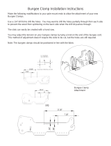
Bungee Clamp Installation
There are four Bungee Clamps provided with your
Mini Pinni Quilting Frame. The Bungee Clamps
allow you to easily add side tension to your quilt
fabric. Clip your Bungee Clamps to the quilt fabric,
then insert the loose Bungee end through the
Bungee Holder as shown in Fig. BC1-1, pulling it
down to lock it into place.
Pulling down on the bungee
to lock it into place.
Fig.BC1-1

18
Grace Speed Control
The Grace Speed Control is designed
to work with many models of Sewing
Machines
Connecting to your sewing machine:
For Technical Assistance
please contact:
The Grace Company
1-800-264-0644
Speed Control-
Allows you to set
your machine to
desired stitch-speed
ranging from slow to
full speed.
Thread Cutter-
Activates your sewing
machine thread
cutter (if available).
Pulse Button-
Machine stops
when you re-
lease, or use for
single stitch.
On/Off-
Press for on,
press again for
off
Back Panel
Switch Cover
Machine Setting Switch
Front Panel
Thread Cutter
Plug-In
For Machines
with thread
cutting options
Jack Plug-In
Jack Plug-In
Thread Cutter
Plug-
In
Jack Plug-In Adapter
(To Sewing Machine)
(To Speed Control Jack)
ON
12
3
456
7
12
3
4567
ON
12
3
4567
ON
Setting 2
Baby Lock / Brother
Janome / New Home
Setting 1
Setting 3
Bernina / Pfaff
Juki / Singer
black indicates switch position
black indicates switch position
black indicates switch position
*The Grace Speed Control
Switch is compatible with
most DC-powered machines.
DC-powered machines
usually have a separate foot
pedal plug in and power
cord plug in. *
(To Sewing Machine)
Machines that use the
three-prong connector
require no settings

19
Optional Accessories
There are many optional accessories available for your Aluminum Frame Quilting frame. Check with
your local dealer or visit www.graceframe.com to see all of the accessories available, as new items
are being developed regularly.
Sewing Tips
• Be careful not to sew too close to the edge, to prevent hitting your Bungee Clamps, or running off
the edge of the quilt. Also, if you are using side leaders, avoid accidentally stitching the leaders to your
quilt.
• If your quilt will fit onto your frame Length-wise attach your quilt’s fabric to the rails along its length.
You will have to roll the quilt less often, since your work surface will be as large as possible. Also, the
quilt will not be as large under the arm of the machine when you get to the end.
• You will need 4-5 bobbins to quilt a small sized quilt (less than a queen).
• Make sure to turn off your sewing machine any time you leave your quilting room.
• Keeping the fabric on the Take-Up Rail just slightly above the bed of the sewing machine, yields the
best results. If the fabric is too high off the bed, thread and needle breakage may occur. If it is press-
ing down on the bed of the machine it will be difficult to roll the sewing machine on the frame.
• When rolling the quilt, pull the batting a little to each side to make sure that it is not bunching. After
rolling and tightening all the rails, check under the quilt to see that the back is smooth.
/