Page is loading ...

Pg. 1
DID:071006
Copyright May 2006
Jim M. Bagley, GraceWood, Inc
(Reproduction Prohibited)
Print Date 7-10-06
Next Generation Quilting Frame

Pg. 2
DID:071006
Next Generation Quilting Frame
By The Grace Company
Parts List
Parts List A and B ............................................................................................ 3-4
Hardware Parts List ......................................................................................... 5
Manufacturer Info ........................................................................................... 6
Assembly Steps:
Step 1: Outer Leg Sub-Assembly ..................................................................... 7
Step 2: Frame End Assembly ........................................................................... 8
Step 3: Outer Leg Assembly ............................................................................ 8
Step 4: Middle Leg Assembly ........................................................................... 9
Step 5: Table Sub-Assembly ............................................................................ 9
Step 6: Frame Assembly ................................................................................. 10
Step 7: Shelf Brace Attachment ....................................................................... 11
Step 8: Track Attachment ................................................................................ 11
Step 9: Shelf Attachment ................................................................................ 12
Step 10: Table Surface Attachment .................................................................. 12
Step 11: Rail Bracket Attachment .................................................................... 13
Step 12: Rail Assembly ................................................................................... 14
Step 13: Rail Attachment to Table Assembly ..................................................... 15
Step 14: Top Plate Sides ................................................................................. 15
Step 15: Top Plate Final Assembly ................................................................... 16
Step 16: Bottom Plate Assembly ...................................................................... 17
Step 17: Bottom Plate Placement .................................................................... 17
Step 18: Top Plate Placement .......................................................................... 17
Step 19: Sewing Machine Placement ................................................................ 18
Step 20: Leveling the Table ............................................................................. 18
Step 21: Handle Adjustment ........................................................................... 18
Step 22: Upper Laser Pointer Attachment ......................................................... 19
Step 23: Lower Laser Pointer Attachment ......................................................... 19
Step 24: Crib Table Assembly .......................................................................... 20
Step 25: Crib Shelf Brace Attachment .............................................................. 21
Step 26: Crib Track Attachment ....................................................................... 21
Step 27: Crib Shelf Attachment ....................................................................... 22
Step 28: Crib Table Surface Attachment ........................................................... 22
Fabric Installation ....................................................................................... 23
Step 1: Quilt Batting To Batting Rail ................................................................. 24
Step 2: Quilt Top To Quilt Top Rail ................................................................... 24
Step 3: Backing to Backing Rail ....................................................................... 24
Step 4: Attaching Quilt Layers to Take-Up Rail .................................................. 25
Rolling your Fabric ........................................................................................... 26
Turning Quilt Around ....................................................................................... 26
Making Cloth Leaders ...................................................................................... 27
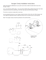
Bungee Clamp Installation ............................................................................... 28
Optional Accessories ........................................................................................ 28
Sewing Tips .................................................................................................... 28

Pg. 3
DID:071006
(2) Table Surface
(2) Shelf Surface
(4) Track Support
Pre-Installed (4) 3/8" screw (4) 1/4"nut
(4) Shelf Brace
(4) Table Brace
(4) Outer Leg Brace (Shorter)
Pre-Installed (2) 3/8" screw (2) 1/4"nut
(4) Middle Leg Brace (Longer)
Pre-Installed (2) 3/8" screw (2) 1/4"nut
(1) Right Frame End
(4) Ratchet
(2) Fabric Layers
Rail Bracket (FLRB)
(2) Take-Up Rail
Bracket (TURB)
(4) Longer Rail
(4) Rail Coupler
(2) 120" Plastic Track
(4) Rail End
(1) Left Frame End
(4) Shorter Rail
(2) 60" Plastic Track (Crib Track)
(1) Laser Pointer Assembly
(1) Laser Pointer
Lower Assembly
(4) Bungee Bracket
Left Take-Up Rail Bracket
Pre-assembled (1) Left Aluminum Take-Up
Rail Bracket (1) 1/4" X 1" RHSN Bolt (2)
1/4" X 3/4" RHSN Bolt (3) 1/4" Knob (1)
Bungee Arm (1) Bungee Arm Retaining
Ring (1) Bungee Positioning Part "A" (1)
Bungee Positioning Part "B" (1) Bungee
Arm Bolt Holder
Right Take-Up Rail Bracket
Pre-assembled (1) Right Aluminum Take-Up
Rail Bracket (1) 1/4" X 1" RHSN Bolt (2)
1/4" X 3/4" RHSN Bolt (3) 1/4" Knob (1)
Bungee Arm (1) Bungee Arm Retaining
Ring (1) Bungee Positioning Part "A" (1)
Bungee Positioning Part "B" (1) Bunbee
Arm Bolt Holder
Left Fabric Layers Rail Bracket
Pre-assembled (1) Left Aluminum Fabric Layers
Rail Bracket (1) 1/4" X 1" RHSN Bolt (2) 1/4" X
3/4" RHSN Bolt (3) 1/4" Knob (1) Bungee Arm
(1) Bungee Arm Retaining Ring (1) Bungee
Positioning Part "A" (1) Bungee Positioning Part
"B" (1) Bungee Arm Bolt Holder
Right Fabric Layers Rail Bracket
Pre-assembled (1) Right Aluminum Fabric
Layers Rail Bracket (1) 1/4" X 1" RHSN Bolt (2)
1/4" X 3/4" RHSN Bolt (3) 1/4" Knob (1)
Bungee Arm (1) Bungee Arm Retaining Ring (1)
Bungee Positioning Part "A" (1) Bungee
Positioning Part "B" (1) Bunbee Arm Bolt Holder
(6) Leg
Assembly
Parts List A

Pg. 4
DID:071006
(2) Right
Handle
(1) Left Carriage Side
(1) Laser Handle Mount
(2) Lamp Bracket
(4) Handle
Bolt Holder
(4) Handle
Rotate Link
(1) Laser Pointer
(Batteries not Included)
(2) Laser Pointer
Ball Swivel
(2) Laser Pointer
Ball Swivel Clamp
(2) Handle Brace
(2) Left
Handle
(2) Bottom Plate Side Pre-Installed (1) Plastic Track
(4) 3/4" Screws
(2) Bottom Plate End
Pre-Installed (2) Wheels pre-attached)
(1) Bottom Plate End (Floating Wheels)
Pre-Installed (2) Wheels
(2) Handle/Brace Assembly
(1) Top Plate
Pre-Installed (4) Wheels
(1) Left Lower Carriage Side
(pre-assembled (1) Left Handle Verticle Adjusting Base (1)
Handle Slide Cam Clamp Lever (1) Cam Clamp Wedge (1)
Handle Slide Cam Clamp Lever Rod)
(1) Right Lower Carriage Side
(pre-assembled (1) Right Handle Verticle Adjusting Base (1)
Handle Slide Cam Clamp Lever (1) Cam Clamp Wedge (1)
Handle Slide Cam Clamp Lever Rod)
(1) Right Upper Carriage Side
(pre-assembled (1) Right Handle Horizontal Adjusting Base (1) Handle Slide
Cam Clamp Lever (1) Cam Clamp Wedge (1) Handle Slide Cam Clamp Lever
Rod (1) Lower Carriage Aluminum)
(2) Upper Carriage Aluminum
(4) Upper Carriage
Aluminum End Cap
(1) Right Carriage Side
Pre-Installed (1) Right Handle
Horizontal Adjusting Base (1) Lower
Carriage Aluminum) (1) Right Handle
Verticle Adjusting Base (1) Upper
Carriage Aluminum (2) Upper
Carriage Aluminum End Cap
(1) Left Carriage Side
Pre-Installed (1) Left Handle
Horizontal Adjusting Base (1) Lower
Carriage Aluminum) (1) Left Handle
Verticle Adjusting Base (1) Upper
Carriage Aluminum (2) Upper
Carriage Aluminum End Cap
(1) Left Upper Carriage Side
(pre-assembled (1) Left Handle Horizontal
Adjusting Base (1) Handle Slide Cam Clamp Lever
(1) Cam Clamp Wedge (1) Handle Slide Cam Clamp
Lever Rod (1) Lower Carriage Aluminum)
(1) Lower Left
Carriage Side
(1) Lower Right
Carriage Side
(1) Upper Left
Carriage Side
(1) Upper Right
Carriage Side
Left Take-Up Rail Bracket
Right Take-Up Rail Bracket
Left Fabric Layers Rail Bracket
Right Fabric Layers Rail Bracket
Parts List B

Pg. 5
DID:071006
Pre-Installed
(24) Plastic Knob
(8) 1/4 X 3/4" Carriage Bolt
(8) pre-installed
(12) 1/4" Flat Washer
(12) pre-installed
Pre-Installed (8) #10
Square Nut
(12) 1/4" X 2" Hex Bolt
(10) pre-installed
(4) 1/4" X 1-1/4" Hex Bolt
(4) pre-installed
(2) #10 X 1/4" X 1/2" Socket
Head Shoulder Bolt (SHSB)
(2) pre-installed
Pre-Installed (8) 1/4" X 1"
Socket Button Head Cap
Screw (SBHC)
Pre-Installed (8) 1/4" X 3/4"
Socket Button Head Cap Screw
(SBHC)
(8) #10 X 3/8" Socket Head Counter Sink
Screw (SHCS) in a bag
(16 #10 X 3/8" Socket Button
Head Cap Screw (SBHC) in a bag
(6) 1/4" X 3/8" Socket Button
Head Cap Screw (SBHC) in a bag
(8) 1/4" X 1/2" Socket Button Head
Cap Screw (SBHC)
(10) 1/4" Nut Pre-
Installed in a bag
(4) Fabrifast Tubing
(4) 1/4" X 3/4" Hex Bolt
(4) Pre-Installed
(36) 6mm X 10mm Socket
Button Head Cap Screw
(8) 6mm X 12mm Socket Button
Head Cap Screw (SBHC) in a bag
(40) 6mm Square Nut
(8) in a bag
(1) Speed Control Assembly
with instructions & cord
(4) Bungee Clamps
Hardware List
Tools Needed:
7/16” open end wrench
or Adjustable wrench
Phillips Screw Driver (Cordless Preferred)
3mm, and 4mm Allen wenches (provided)
Fabri-Fast Tool (to be used when installing your fabric)
(1) Fabri-Fast Tool

Pg. 6
DID:071006
Innovation and Evolution
Grace Quilting Systems have been
developed over the past two decades
with several original design innovations.
Additionally, because of feedback from
many of the thousands of quilters who
have purchased and use our machine
quilting systems, we have been able to
make a frame that will truly enhance the
entire process of machine quilting from
beginning to end.
WELCOME!
As you begin assembly of your new Aluminum Frame home machine quilting system, keep in the mind the following:
1: The assembly process will be simple and step-by-step.
2: Read through each step completely before beginning that step.
3: Using the parts list as a reference, take the parts out of the box and make sure that you have them all.
4: Identify Hardware Packets: All hardware is separated by type and each packet is labeled for ease in identication.
You will nd packets located in a rectangular box.
Grace Quilting Frames and Hoops

Pg. 7
DID:071006
Step 1: Outer Leg Sub-Assembly
Parts Needed:
4- Leg
4- Outer Leg Brace (Shorter)
Tools Required:
4mm Allen Wrench (Provided)
NOTE: It may be helpful to hold the square Nuts
with a 7/16” Open End Wrench while inserting them
into the “T” slot in the legs.
1-1: The Outer Leg Braces are slightly shorter
than the Middle Leg Braces. Separate the parts
before assembly to minimize the possibility of using
the wrong parts.
1-2: Insert the Square Nut (Pre-installed in the Leg
Brace) into the “T” slot in the leg as shown in
Fig. 1-1.
1-3: Slide (2) Outer Leg
Braces onto (2) Legs, as
shown in Fig. 1-2
1-4: Lay the Leg Assembly
down as shown in Fig 1-2 to simplify
this step. Adjust the rst installed Leg
Brace using another leg brace to measure it’s
location, as shown in Fig. 1-3. Tighten the
6mm X 10mm SBHC screws in the Outer Leg Brace
with a 4mm Allen Wrench to secure them into place.
NOTE: The rst installed Leg Brace will later be used to support
your Aluminum Frame’s shelf. If you would like the shelf to be
higher, or lower than the suggested height be sure to make this
adjustment now, since it may be difcult to make this change at
a later time. Also, remember the height of the brace, and set the
middle leg braces at the same height to ensure that the shelf sits
level.
1-5: The bent ends of the top Outer Leg Brace need to be even
with the top of the leg. This will put the bent-over ange on the
Outer Leg Brace slightly higher than the top of the Leg.
1-6: Tighten the top Outer Leg Brace into it’s proper location
using a 4mm Allen Wrench.
1-7:
Repeat steps 1-2 through 1-6 to complete a total of two (2)
Outer Leg Assemblies.
16"
Leg OutSd ASM
Fig. 1-1
Fig. 1-2
Fig. 1-3
Leg
Outer Leg
Brace
14"
Notice Flange
Location

Pg. 8
DID:071006
Leg OutSd ASM 2
Fig. 3-1
3-1: Attach a Frame End to each Outer Leg Sub-
Assembly. Slide the 6mm Hex Nuts (Pre-installed
in the Frame End) into the “T” Slot’s in the Legs, as
shown in Fig. 3-1.
NOTE: Create a Left and a Right Outer Leg
Assembly by attaching the frame ends as shown in
Fig. 3-2, and Fig. 3-3.
3-2:
Temporarily fasten the Frame Ends about 1”
down from the top of the leg, by tightening the
pre-attached 6mm X 12mm SBHC screws with a
4mm Allen Wrench.
Step 3: Outer Leg Assembly
Parts Needed:
2- Outer Leg Sub-Assembly
1- Left Frame End
1- Right Frame End
Tools Required:
4mm Allen Wrench
Leg OutSd ASM 2
Fig. 3-2
Left
Leg OutSd ASM 2
Fig. 3-3
Right
Frame End
Step 2: Frame End Assembly
Parts Needed:
1- Left Frame End
1- Right Frame End
8- 12mm SHBC Screw
8- 6mm Square Nut
NOTE: To guarantee that you have a Left and Right Frame End, insert the screws through the side of each
Frame End with the Logo’s painted on it.
2-1:
Insert a 12mm SBHC Screw through each of the holes indicated in Fig. 2-1 (on the Left, and Right
Frame Ends). Partially thread a 6mm Nut onto the exposed end of each 12mm SBHC Screw (Thread the nut
on until the screw barely shows on the outside of the nut, the nut shouldn’t easily fall off the screw, but will
be very loose).
Left Frame End
Right Frame End
6mm square Nut
12mm SBHC Screw
Fig. 2-1

Pg. 9
DID:071006
A
DETAIL A
SCALE 1 : 1.5
B
DETAIL B
SCALE 1 : 1.5
T Slot ASM
Step 5: Table Sub-Assembly
Parts Needed:
1- Outer Leg Assembly
1- Middle Leg Assembly
2- Track Support
Tools Required:
4mm Allen Wrench
7/16” Open End Wrench (Optional)
We recommend having someone hold up one end of the track
support to help you with this step.
5-1: Attach a Track Support to the Outer Leg Assembly by sliding the two
(2) Hex Nuts (Pre-installed on the Track Support) into the “T” slot in the
leg. Slide the Track Support onto the Leg completely (until the ange on
the Track Support is against the top of the Leg)
5-2:
Secure the Track Support to the leg by tightening the 6mm X 10mm SBHC Screws with a 4mm Allen
Wrench.
5-3: Attach the other end of the Track Support to the Middle Leg Assembly by sliding the two (2) Square
Nuts into the “T” slot in the Leg as shown in Fig. 5-3. (Do not tighten the 6mm X 10mm SBHC Screws yet.
Leaving the screws loose will simplify attachment of the Track Support in Step 6-3, and Track attachment in
Step 8.)
5-4: Repeat steps 5-1 to 5-3 to attach a Track Support to the other side of the Table Sub-Assembly. (Fig.
5-4 shows completed Table Sub-Assembly)
Fig. 5-1
16"
Leg InSd ASM
Fig. 4-1
Leg
Middle Leg
Brace
NOTE: The maximum width for a quilt
made in the Crib Conguration is 50”. If you
will be making quilts larger than 50” wide we
recommended that you build your Quilting Frame
full size.
Step 4: Middle Leg Assembly (Queen Only)
Parts Needed:
2- Leg
4- Middle Leg Brace (Longer)
Tools Required:
4mm Allen Wrench
You do not need to complete Step 4 if you are building your Quilting Frame in the Crib Conguration. Skip
to Step 24 (Crib Setup Instructions Pg. 20) to setup your frame for Crib Size quilts. If you are building the
Crib Size Frame keep the parts listed in Step 4, so that they will be available if you decide to build the Full
Size Frame at a later time.
4-1: Slide the Square Nuts pre-installed in the four (4) Middle Leg Braces onto the “T” Slots in the two (2)
remaining legs as shown in Fig. 4-1.
4-2: Set the lower Leg Braces at the height previously set in
Step 1-4, use a Leg Brace to measure the location. (See Fig. 4-2)
4-3: Secure the lower Leg Braces to the Legs by tightening the 6mm X 10mm SBHC Screws with a 4mm
Allen Wrench.
4-4:
Finally set the top Leg Braces even with the top of each Leg. Tighten the 6mm X 10mm SBHC Screws
with a 4mm Allen Wrench to secure the braces in place.

Pg. 10
DID:071006
Table ASM 1
A
DETAIL A
SCALE 1 : 3
Fig. 5-2
Table ASM 1
A
DETAIL A
SCALE 1 : 3
Fig. 5-3
Track
Support
Table ASM 1
A
DETAIL A
SCALE 1 : 3
Fig. 5-4
Step 6: Frame Assembly
Parts Needed:
1- Frame Sub-Assembly
1- Outer Leg Assembly
2- Track Support
We recommend having someone hold up one end of the track support to help you with this
step.
6-1: Attach a Track Support to the remaining Outer Leg Assembly by sliding two (2) of the Square Nuts
(Pre-installed on the Track Support) into the “T” slot in the leg. Slide the Track Support onto the Leg
completely (until the ange on the Track Support is against the top of the Leg).
6-2:
Secure the Track Support to the leg by tightening the 6mm X 10mm SBHC Screws with a 4mm Allen
Wrench.
6-3: Attach the other end of the Track Support to the Middle Leg, (part of the Table Sub-Assembly) by
sliding the two (2) Square Nuts into the “T” slot in the Leg as done in Step 5-3, and as shown in Fig. 5-
2. (Leave all four (4) of the 6mm X 10mm SBHC Screws in the Middle Leg loose. They will be
tightened in Step 9-2)
6-4:
Repeat steps 6-1 to 6-3 to
attach a Track Support to the other
side of the Table Assembly.
Tools Required:
4mm Allen Wrench
7/16” Open End Wrench (Optional)
Table ASM 2
Fig. 6-1

Pg. 11
DID:071006
Step 7: Shelf Brace Attachment
Parts Needed:
1- Table Assembly
4- Shelf Brace
6- 1/4” X 3/8” SBHC Screw
6- 1/4” Nut
Tools Required:
4mm Allen Wrench
7/16” Wrench
Fig. 7-1
1/4” Nut
1/4” X 3/8”
SBHC Screw
Outer Leg
Shelf Brace
Outer Leg
Brace
Note: While attaching the Shelf Braces notice how the
brace is attached to the Frame.
Fig. 7-1, and Fig 7-2 show proper Shelf Brace Attachment.
We Recommend that you have someone hold up the end
of the shelf brace near the middle of the Frame while
you attach the Shelf Braces to the outer leg Braces.
7-1: Attach a Shelf Brace to the lower Leg Brace
on the Outer Leg Assembly with a 1/4” X 3/8”
SBHC Screw, and secure into place with a 1/4”
Nut, as shown in Fig. 7-1.
7-2: Attach another Shelf Brace to the lower Leg Brace on the Outer
Leg Assembly, on the opposite end of the Frame as the one that you
attached in step 6-1. Use the same procedure outlined in step 6-1 to
attach the Shelf Brace. See Fig. 7-2.
7-3: Attach the other end of the Shelf Braces to the lower Leg Brace on the
Middle Leg Assembly by inserting a 1/4” X 3/8” SBHC Screw
through the hole in a Shelf Brace, and then through the
hole in the Leg Brace. Finally insert the screw through
the hole in the Shelf Brace that is on the other side of
the Leg Brace. Secure the parts together with a 1/4”
Nut.
7-4:
Repeat steps 7-1 through 7-3, to attach Shelf
Braces to the other end of the Leg Braces. See Fig. 7-3.
Fig. 7-2
1/4” Nut
(Attach in Step 6-3)
1/4” X 3/8”
SBHC Screw
Middle
Leg Brace
Shelf Brace
Middle Leg
Fig. 7-3
Shelf Brace 2
Step 8: Track Attachment
Parts Needed:
1- Table Assembly
2- 120” Plastic Track
Tools Required:
4mm Allen Wrench
8-1: Snap a 120” Plastic Track into the Track
Supports on the Front, and also the Back of the Table
Assembly as shown in Fig. 8-1. Start at one end
of the track, and work your way down as the track
snaps into place. (You may need to lightly tap the
track to get it in place.)
8-2: After the Plastic Track is in place Tighten all of the screws holding the Track Supports to the Middle
Legs with a 4mm Allen Wrench. (These screws were left loose in step 6-3.)
Track Install
Fig. 8-1
120” Plastic Track
NOTE: To remove the track, start at one end, pry the track out with a small screw driver.

Pg. 12
DID:071006
DETAIL A
Frame Side Adj
Fig. 8-2
DETAIL A
Frame Side Adj
Fig. 8-3
Step 9: Shelf Attachment
Parts Needed:
1- Table Assembly
2- Shelf Surface
9-1: Attach the plastic Shelf Surface,
with it’s textured side UP to the
Shelf Braces, and the lower Leg Braces
with the Pre-Installed Double Sided
Tape, as shown in Fig. 9-1.
NOTE: To prevent the Shelf Surface from being attached out of square remove
the backing from the tape, starting at one end of the Frame, and then only
remove the Tape Backing in one (1) foot sections. Line up the Shelf
Surface with the Shelf Braces, and press rmly in place before
removing the next one (1) foot section of Tape Backing.
Repeat this process until the entire Shelf Surface is
attached.
9-2: Repeat Step 9-1 so that both plastic
Shelf Surfaces are attached to the Table
Assembly.
#10 X 1/2" Counter sink
Socket Head Screw
Bottom Shelf
Shelf Attatchment
Shelf Surface
Fig. 9-1
8-3: Adjust the Frame Ends so that their top edges are even with the top edges of the Track supports, as
shown in Fig. 8-2, and Fig. 8-3.
Step 10: Table Surface Attachment
Parts Needed:
1- Table Assembly
2- Table Surface
4- Table Brace
Tools Required: 3mm Allen Wrench
#
10 X 1
/
2
"
Counter Sin
k
Soc
k
et Hea
d
Screw
T
ab
l
e
Table Attatchment
Table Attatchment 01
Fig. 10-1
Table Surface
Table Brace
#10 X 3/8”
SHCS Screw
Front
Back
10-1: Attach all four (4) Table Braces to
the Track Supports with the Pre-Installed #10
screws. The Table Braces are attached to the bottom
side of the Track Support Flange, with the Tape on
the Table Brace facing up (Remove Pre-Installed #10
screws from Table Braces before attaching them to
the Track Supports).
10-2: Attach the Table Surface to the Frame using the
same method used to attach the Shelf Surface in step 8,
removing the Tape Backing in one (1) foot sections. Make
sure that the Table surface is placed onto the Frame with it’s
textured surface facing up. (Notice that the slots cut
in the plastic Table Surface are closer to the back of
the Table Assembly.) The Slots are in the table to attach the
Pattern Perfect, and other optional accessories.
10-2:
Repeat Step 10-1 so that both plastic Table Surfaces are attached to
the Table Assembly.

Pg. 13
DID:071006
1/4" X 3/4"
Carriage Bolt
PME's 01
Step 11: Rail Bracket Attachment
Parts Needed:
1- Table Assembly
2- Fabric Layers Rail Bracket
2- Take-Up Rail Bracket
11-1: Remove 1/4” Carriage Bolts, and Plastic Knobs
from the lower, slotted section of the Take-Up Rail
Brackets, and Fabric Layers Rail Brackets.
11-2: Insert a 1/4” X 3/4”
Carriage Bolt through each
of the two (2) square holes
located at the front of each
of the Frame Ends, as shown in Fig. 11-1, and Fig. 11-2. The Bolts are inserted from the inside of the Table
assembly, facing out, this is shown more clearly in Fig. 11-2.
11-3:
Now place a Fabric Layers Rail Bracket onto the 3/4” Carriage Bolts, inserted in step 11-2. The
Carriage Bolts go through the large slot in the side of the Fabric Layers Rail Bracket.
11-4:
Secure the Fabric Layers Rail Bracket to the Table assembly by threading a 1/4” Plastic Knob onto
each Carriage Bolt.
11-5:
Repeat Steps 11-2 through 11-4 on the other end of the Table Assembly to attach the other Fabric
Layers Rail Bracket.
11-6: Insert two (2) 1/4” X 3/4” Carriage Bolts through one of the ve (5) available attachment positions
indicated in Fig. 11-1. (The square holes are arranged in vertical pairs, which are provided to allow
many different sizes of sewing machines to be used on the Quilting Frame. Try the middle position rst,
and adjust later if more, or less quilting area is desired.)
Fig. 11-1
Left Frame End - Inside View
Fabric Layers Rail Bracket
Attachment Location
Bolts pre-attached in Fabric Layers
Rail Bracket
Take-Up Rail
Bracket Attachment
Locations
Table Details
Omitted for clarity
(This is the Frame End
shown by the word
“Front” in Fig. 9-1)
(Pre-attached in
Take-up Rail Bracket)
Take-Up Pole
Mount End
Quilt Layers
Pole Mount End
1/4" Plastic Knob
PME's Attatchment 02
Fabric Layers Rail Bracket
(Fabric Layers Rail Brace)
1/4” Plastic Knob
Take-Up Rail Bracket
(Take-Up Rail Brace)
Fig. 11-2
11-7: Now attach the Take-Up Rail
Bracket to the Table Assembly by
placing it onto the two (2) screws, just
inserted into the table. The two (2) screws go through the large slot in
the lower section of the Take-Up Rail Bracket. When you place the Take-
Up Rail Bracket onto the Table Assembly be sure that the Bungee Arm
near the top of the bracket is closer to the Fabric Layers Rail Bracket, as shown in Fig. 11-3.

Pg. 14
DID:071006
Fig. 11-3
Step 12: Rail Assembly
Parts Needed:
4- Ratchet
4- Rail End
16- #10 X 3/8” SBHC Screw
4- Rail Coupler
4- Longer Rail
4- Shorter Rail
Tools Required:
3mm Allen Wrench
Fig. 12-1
Rail Coupler
3/8” SBHC Screw
Rail
Crib Rail Assembly
Parts Needed:
4- Ratchet
4- Rail End
8- #10 X 3/8” SBHC Screw
4- Shorter Rail
Tools Required:
3mm Allen Wrench
NOTE: If you are assembling your Quilting Frame in the
Crib Conguration use the Crib Rail Assembly parts list.
Also, if assembling the Crib Conguration, skip Step 12-1.
11-8:
Secure the Take-Up Rail Bracket to the Table Assembly with two (2) 1/4” Plastic Knobs.
11-9: Repeat Steps 10-6 through 10-8 to attach the remaining Take-Up Rail Bracket to the other end of the
Table Assembly.
12-1: Attach two (2) Rails to each Rail Coupler using one
#10 X 3/8” SBHC Screw per Rail, as shown in Fig. 12-1.
Tighten the #10 Screws with a 3mm Allen Wrench (Be sure
to use a short, and long rail for each rail assembly).
12-2:
Attach a Ratchet to one of the ends of each of the rails with a #10 X 3/8” SBHC Screw, as shown in
Fig. 12-2 (Slide Rail into ratchet until you can see the entire hole in the nut).
12-2: Finally attach a Rail End to the open end of each of the rails with a #10 X 3/8” SBHC Screw, as
shown in Fig. 12-3 (Slide Rail into Rail End until you can see the entire hole in the nut).
Fig. 12-2
Ratchet
Fig. 12-3
Rail End

Pg. 15
DID:071006
Step 13: Rail Attachment to Table Assembly
Parts Needed:
4- Rail Assembly
4- Table Assembly
Rail End Cap (Left End), or
Ratchetting Rail End Cap (Right End)
Rail Attatchment 01
Table, and Rail details
omitted for clarity.
WARNING: Ratchet, or Rail End will become damaged if Rail
is allowed to sag down while one end is attached to a Rail Bracket.
We Recommend that you have someone hold up one end of the rail
that you are working with to help you with this step.
13-1: Slide a Ratchet onto one of the wide slots in one of the Fabric Layers
Rail Bracket’s on either end of the Table Assembly. Depress the Ratchet
Mount Buttons while sliding the Ratchet into place. When the Ratchet is in
place release the Ratchet Mount Buttons. The buttons should snap into the
mounting holes in the Fabric Layers Rail Bracket.
13-2: Slide the Rail End, on the other end of the Rail into the same slot on
the Fabric Layers Rail Bracket at the other end of the Table Assembly. Again,
depress the Ratchet Mount Buttons while sliding the Rail End into place.
Once the Rail is in place the Ratchet Mount Buttons should snap into the
mounting holes in the Fabric Layers Rail Bracket.
13-3:
Repeat Steps 13-1, and 13-2 to attach the remaining two (2) rails to
the Fabric Layers Rail Bracket’s at each end of the Table Assembly. Make
sure that all of the Ratchets are mounted on the same end of the
Table Assembly.
13-4: Attach the nal Rail assembly to the Take-Up
Rail Bracket exactly the same way as you attached
all of the other rails to the Fabric Layers Rail Bracket.
Again, remember to attach the Ratchet to the
same end of the Table Assembly as all of the
other Ratchets.
Fig. 13-1
Fig. 13-2
Step 14: Top Plate Sides
Parts Required:
4- 1/4” X 3/4” HEX Bolt
4- 1/4” Nut
1- Lower Left Carriage Side
1- Lower Right Carriage Side
1- Right Upper Carriage Side
1- Left Upper Carriage Side
1- Top Plate
Tools Required:
7/16” Wrench
Attach the Carriage Sides to the Top Plate.
14-1:
Next insert a 1/4” X 3/4” HEX Bolt through each of the holes
in the Lower Left Carriage Side, and then throught the holes in the
top plate.
14-2: Secure the Lower Left Carriage Side to the Top Plate by
applying nuts to the exposed end of the HEX Bolts. Tighten the
nuts securely with a 7/16” wrench. Fig 14-1.
14-3: Repeat Steps 14-1 through 14-3, this time using the Lower Right Carriage Side to attach the
Right Carriage Side to the Top Plate.

Pg. 16
DID:071006
1/4" Nut
3/4" HEX Bolt
Top Carriage ASM 1
1/4" Nut
3/4" HEX Bolt
Top Carriage ASM 1
Fig. 14-1
Step 15: Top Plate - Final Assembly
Parts Required:
2- Handle Brace Assembly
1- Top Plate Assembly
15-1: Remove the pre-installed
2” Hex Bolts, and 1/4” Plastic
Knobs from the ends of each
Handle Brace Assembly.
15-2: Pull the Carriage Sides
apart slightly, to allow the Handle
Brace Assembly to be inserted
between them. The round stems on each
end of the Handle Braces Fit into the round
holes in the Plastic End Caps. Insert a Handle
Brace Assembly into the front as well as the
back of the Top Plate Assembly.
15-3: After the Handle Brace Assemblies are in place, insert a 2” Hex Bolt through the Handle brace, push
it all the way through the Plastic End Cap.
15-4:
Secure the Handle Brace Assemblies into place by fastening a 1/4” Plastic Knob onto each 2” Hex
Bolt.
2" Hex Bolt
1/4" Plastic Knob
Top Carriage ASM 2
Front
Back
1/4” Plastic Knob
2” Hex Bolt
Fig. 15-1
Lower Right
Carriage Side
Lower Left
Carriage Side
Angled Side
Facing Back
Adjusting Lever
(Not Visible)
Adjusting Lever
Upper Right
Carriage Side
Upper Left
Carriage Side
Fig. 14-2
NOTE: The Plastic Caps on the ends of the upper aluminum parts have teeth on one side, and are smooth
on the other side. Make sure that when the Upper Carriage sides are installed that the teeth face towards
the inside of the carriage.
14-5: Release the Adjusting Levers on each of the Lower Carriage Sides. Now Insert the Upper Carriage
Sides into the Lower Carriage Sides, and lock them into place with the Adjusting Levers.

Pg. 17
DID:071006
Step 16: Bottom Plate Assembly
Parts Required:
2- Bottom Plate Side
2- Bottom Plate End
Tools Required:
4mm Allen Wrench
Bottom Plate Side
Bottom Plate End
1/2” Screw
16-1: Remove the Pre-Installed
1/2” Screws from all of the
Bottom Plate Sides.
16-2: Attach the Bottom Plate
Ends to the Bottom Plate Sides
using the 1/2” screws that you
removed in step 16-1. Make
sure that the Bottom Plate Ends are attached with their wheels facing in, as shown in Fig. 16-1.
Step 17: Bottom Plate Placement
Parts Required:
1- Bottom Plate Assembly
1- Table Assembly - Complete
Fig. 17-1
Place Bottom Plate onto the Table Assembly.
17-1: First, remove the Take-Up Rail from the Table Assembly.
This is the Rail located right over the middle of the Table, as
shown in Fig. 16-1.
17-2: Make sure that all four (4) wheels on your Bottom Plate
are on the Plastic Track. The Bottom Plate should roll smoothly
on the Track.
Fig. 16-1
Step 18: Top Plate Placement
Parts Required:
1- Top Plate - Final Assembly
1- Table Assembly - Complete w/Bottom Plate
Fig. 18-1
Place the Top Plate Assembly onto the Bottom Plate, as shown in
Fig. 18-1.
18-1: Make sure that all four (4) wheels are on the track,
located on the top side of the Bottom Plate, and that the Top
Plate rolls smoothly.
NOTE: The completely assembled Top Plate, with Bottom
plate is called the Carriage, and will be referred to as the carriage
throughout the remaining text, except for when instructions refer
to features only on one item or the other.

Pg. 18
DID:071006
Adjusting Lever
Fig. 19-1
Loosen Knobs
Fig. 19-2
Fig. 19-3
19-4: Roll the Carriage all the way to one end of the Table.
19-5: Now, put the Take-Up Rail through the open area
above the throat of your Sewing Machine.
19-6: Attach the Take-Up Rail to the Take-Up Rail Brackets
as previously done, in Step 13-4.
Step 20: Leveling the Table
Now that you have completed the assembly of your Aluminum Frame
Quilting Machine, adjust the table so that it is level.
20-1: There are Leveling Feet at the bottom of each of the Table Legs.
Adjust the Leveling feet so that the Carriage will not roll from side to
side, or from front to back when it is left at any point at the table.
Step 21: Handle Adjustment
Adjust the handles for optimal performance, and quilting comfort.
21-1: The Following handle adjustments are possible.
Raise the height of the Handles (Fig. 19-1)
Rotate the Handles, front to back (Fig. 19-2)
Rotate the handles side to side (Fig. 21-2)
The handles can be adjusted wide or narrow (Fig. 21-1)
And nally the Handles can be adjusted forward and back (Fig. 21-3)
Fig. 19-4
Step 19: Sewing Machine Placement
Parts Required:
1- Sewing Machine (Your Sewing Machine)
1- Table Assembly - Complete w/Carriage
Place your Sewing Machine onto the Carriage, as shown in Fig. 19-3.
19-1: Raise the upper portion of the Carriage Sides high enough to allow your sewing machine to slide
onto the Top Plate. Now, lock the Handles into place in the higher position with the Adjusting Lever.
NOTE: You can also gain some clearance for your sewing machine by rotating the Back Handle Brace
Assembly up, out of the way. (Fig. 19-2)
19-2: Place your Sewing Machine onto the Top Plate, and center it, both from side to side, as well as from
front to back.

Pg. 19
DID:071006
Fig. 21-1
Fig. 21-2
Loosen Knobs
Fig. 21-3
Release Adjustment Lever
Step 22: Upper Laser Pointer Attachment
Parts Required:
1- Laser Pointer
1- Top Plate Assembly
Possible mounting
locations
Fig. 22-1
Attach Laser to Carriage Assembly
NOTE: The Laser will be more useful in different
locations, depending on the application. Determine the
best location for the Laser before mounting it.
Fig. 22-1 shows the available Laser Pointer mounting
locations on the upper handles (Mount Laser Here if you want to trace
patterns printed, or placed on the quilt, it is also useful to trace previously
sewn patterns, to improve repeated pattern accuracy.
Fig. 23-1 shows the lower mounting locations. (Mount Laser here if you
would like to trace patterns printed on paper.)
22-1: Remove one of the Plastic Knobs from one of the bolts that hold the
Handle Brace to the Carriage Sides.
22-2: Slide the Laser Pointer onto the exposed end of the bolt.
22-3: Secure the Laser Assembly to the carriage with the knob that you just removed.
Step 23: Lower Laser Pointer Attachment
Parts Required:
1- Laser Pointer
1- Laser Pointer Lower
1- Top Plate Assembly
Fig. 23-1
Mount the Laser Pointer to one of the lower mounting locations.
23-1: Disassemble the Laser Pointer Assembly. (It is shipped ready to
attach to the upper handles.)
23-2: Insert the 2” Hex Bolt through the Laser Pointer Ball Swivel.
23-3: Next insert the Hex Bolt, and Ball Swivel into the Laser Mount, in the Lower Carriage Side. The Hex
Bolt goes through the slot in the front of the Laser Mount.
23-4: While holding the Hex Bolt into the Laser Mount, put the Laser Pointer Ball Swivel Clamp onto the
exposed end of the Hex Bolt.
23-5: Next, slide the Laser Pointer onto the Bolt. The Laser Pointer should sit into the saddle on the end
of the Laser Pointer Ball Swivel Clamp.
23-6:
Secure the Laser Pointer Assembly to the Carriage Assembly by tightening a 1/4” Plastic knob onto
the exposed end of the Hex Bolt.

Pg. 20
DID:071006
Congratulations This completes your Quilting Frame setup.
Please make sure that all screws are completely tightened before continuing.
Now you need to apply your quilt fabric to the Quilting Frame. Detailed instructions explaining how to put
your fabric onto the frame are located on Pg. 23
A
DETAIL A
SCALE 1 : 1.5
B
DETAIL B
SCALE 1 : 1.5
T Slot ASM
Step 24: Crib Table Assembly
Parts Needed:
2- Outer Leg Assembly
2- Track Support
Tools Required:
4mm Allen Wrench
7/16” Open End Wrench (Optional)
NOTE: The maximum width for a quilt made in the
Crib Conguration is 50”. If you will be making quilts
larger than 50” wide we recommended that you build
your Quilting Frame full size.
24-1: Attach a Track Support to the Outer Leg
Assembly by sliding the two (2) Hex Nuts (Pre-installed
on the Track Support) into the “T” slot in the leg. Slide the
Track Support onto the Leg completely (until the ange on the
Track Support is against the top of the Leg).
24-2:
Secure the Track Support to the leg by tightening the 1/4” X
3/8” SBHC Screws with a 4mm Allen Wrench.
24-3: Attach the other end of the Track Support to the other
Outer Leg Assembly by sliding the two (2) Hex Nuts into the
“T” slot in the Leg as shown in Fig. 24-2. Tighten the
3/8” SBHC screws with a 4mm Allen Wrench, as
done in step 24-2.
NOTE: It may be helpful to hold
the Hex Nuts (to keep them aligned
with the “T” slot) with a 7/16”
Open End Wrench while inserting
them into the “T” slot in the legs,
since there is limited clearance,
especially on the Hex Nuts closest
to the ange.
24-4:
Repeat steps 24-1 through
23-3 to attach the other Track
Support to the Outer Legs.
Fig. 24-1
Fig. 24-2
Track Support
/