Page is loading ...

Original

1
CONTENTS
Product Features and Specifications .........................................................1
Installation Requirement..........................................................................2
Steps of Installation................................................................................3
Exploded View.......................................................................................10
Operation Instruction..............................................................................17
Maintenance ..........................................................................................18
Trouble Shooting ....................................................................................20
Lift Disposal ...........................................................................................20

1
I. PRODUCT FEATURES AND SPECIFICATIONS
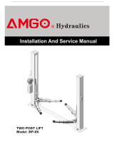
PORTABLE MID-RISED MODEL MR06
●Manual safety lock: mechanical safety locks release, No need air source.
●High speed: From 0-1090mm (43”) in just 21 seconds
●Portable design: It is easy to move the whole lift with the power unit stand
●Adjustable rubber pad included
Fig.1
MODEL MR06 SPECIFICATIONS
Model
Lifting
Capacity
Raised
Height
Lifting
Time
Overall
Length
Platform
Width
Lowered
Height
Motor
MR06
6,000 lbs
43”
26S
74 1/4’’
66 1/4”
5”
1.0HP

2
II. INSTALLATION REQUIREMENT
A. TOOLS REQUIRED
Screw Set
English Spanner (12″)
Wrench sets:(13#、15#、17#、19#)
B. POWER SUPPLY
The electrical source must be 1.0HP minimum. The source cable size must be
2.5mm² and in good condition of contacting with floor.
Fig. 2
Pliers
Grease gun
Hook spanner (40~42mm)

3
III. INSTALLATION STEPS
A. Check the parts before assembly, make sure all the parts are completed.
1. Packaged lift, Parts box, Power Unit and Power Unit Stand.
Move the parts aside, open the outer packing and check the parts according to the
shipment parts list (See Fig. 3).
2. Open the parts box, check the parts according to the part list (See Fig. 4).
Fig. 3
Fig. 4
43
48
33

4
3. Check the parts of the parts bag according to the parts bag list (See Fig. 5).
B. Install the brake
Fig.5
Remove the cover first,
then put the brake in and
tighten the screws
Fig.6
48A
49

5
Then Install hydraulic power unit and fitting (See Fig. 7)
Fig. 7
30
48C

6
C. Install oil hose (See Fig. 8)
Fig. 8
38
38

7
D. Install safety device and cable
1. Put the safety device parts as Fig.9
Item
Part#
Description
QTY
Item
Part#
Description
QTY
1
11640150
Safety stop
1
4
1061K104
Split pinφ3*30
1
2
81400438
Hex bolt M5*10
1
5
10640155
Springφ23*φ27*2
1
3
10510053
Washer
1
6
11640154
Safety pin
1
The safety stop needs to be 10mm high, and
then install wire cable
Fig. 9
Fig. 10
Put the small wire rope into the hole on the screw and then
tighten
6
4
5
2
3
1
48B

8
E. Tighten supporting arm
1. Raise the lift up to 1000mm and lock the safety device, then tighten the self-lock nut.
Make sure the supporting arms not move left/right (See Fig. 11)
Fig. 11
Tighten the self-lock nut
19A
19D
19B
19C
24
50

9
Push Button
F Install electric system
Connect the power source on the data plate of Motor
Note: 1. For the safety of operators, the power wiring must contact the floor well.
2. Pay attention to the direction of rotations when using three phase motors.
Single phase motor (See Fig. 12)
1. Connecting the two power supply wires (fire wire Land zero wire N) to terminals of
AC contactor marked L1, L3. The ground wire is connected to the ground wire
terminal.
Fig. 12
Power Supply
Power Wires

10
IV. EXPLODED VIEW
Model MR06
Fig. 13
9A
19
18
44
45
46
47

11
PARTS LIST FOR MODEL MR06
Item
Part#
Description
QTY.
Note
1
11640001
Platform
1
2
11640002A
Stackable Adapter Bracket
4
3
11209052B
Stackable Adapter (2.5”)
4
3A
11209051B
Stackable Adapter (1.5”)
4
4
10201046A
Rubber pad assy.
4
4A
10420138
Socket bolt M6*16
4
4B
10209134
Rubber pad
4
4C
11680030C
Supporting pad
4
5
10209009
Cup Head Bolt
16
6
10680004
Rubber Pad
4
7
10640003
Supporting pad
4
8
11640023A
Limit pin
4
9
11640004
Supporting arm
4
10
10640005
Washer
10
11
10640109
Washer
4
11A
10620022
Self-locking Nut
6
12
10640116
Cylinder
2
13
10206032
Snap Ring
12
14
11640057
Pin for Cylinder Connecting
2
14A
11640012
Pin
2
15
11640006A
Pin for Cylinder
2
16
11640017B
Outer Scissor
1
17
11640009
Inner Scissor Pin
2
18
11640130
Safety Bar Set
2
19
19A
11640134
Slide limit block
4
19B
11640135
Slide stop
4
19C
11640136
Safety Pin
4
19D
10640127
Spring
8
20
10203004A
Bronze Bush
8
21
10420023A
Washer
2
22
10420132A
Bronze Bush
4
23
11640022
Roller
2
24
10630107
Split Pin
10
25
11640016B
Inner Scissor
1
26
10610003A
Slider
2
27
10209060
Fitting 1/4JIC(M)*1/4JIC(M)*1/4NPT(M)
1
28
10640114-01
Oil Hose 1/4*215
1
29
10420097
900Fitting 1/4JIC(M)*1/4NPT(M)
1
30
071103
Power Unit
1
31
10209003
Hex Bolt
4

12
Item
Part#
Description
QTY.
Note
32
10209005
Self Locking Nut
4
33
10640138
Power Unit Stand
1
34
10206006
Washer 12
2
35
10201005
Split Pin
2
36
1003275021
White Roller
2
38
1003015002
Oil Hose Assy (include spring)
1
39
10201046A
Rubber Pad Assy.
4
40
10420138
M6*16 Socket Bolt
4
41
10209134
Rubber Pad
4
42
11680030C
Support Frame
4
43
10640500A
Part Box
1
44
11640150
Safety Guard
1
45
11640154
Safety Guard Pin φ22*74
1
46
11640153
Self Locking Suport Tube
1
47
11640699
Self Locking Support Shaft
φ45*493
1
48
10640141
Brake Handle Assy (with cable)
1
48A
10640115
Brake handle
1
48B
10640156
Safety Cable φ1.5*4345mm
1
48C
10640121
Brake wire pipe φ5*φ2*4060mm
1
49
10640126
Brake handle rubber cover
1
50
10640133
Safety Cable φ2.5*810mm
4

13
1. CYLINDER (10640116)
PARTS FOR HYDRAULIC CYLINDER
Item
Part#
Description
QTY.
Note
12-1
11640657
Bore Weldment
2
12-2
11640031A
Piston Rod
2
12-3
10201034
Bleeding Plug
2
12-4
11203083
Head Cap
2
12-5
10209078
Dust Ring
2
12-6
10201032
O - Ring
2
12-7
10203084
O - Ring
2
12-8
11203079
Piston
2
12-9
10206069
O-Ring
2
12-10
10203082
O-Ring
2
12-11
10410087
Y-Ring
2
12-12
10410086
Support Ring
2
12-13
10206071
Nut
2
12-14
10620064
Greasing Fitting
4
Fig.14

14
2. MANUAL POWER UNIT (071103)
Parts for Manual power unit
Item
Part#
Description
QTY.
Note
1
81400180
Rubber pad
2
2
81400250
Start capacitor
1
3
81400200
Run capacitor
1
4
10420148
Cup head bolt with washer
4
5
81400066
Cover for capacitor
2
6
81400363
Motor connecting shaft
1
7
80101013
Manifold block
1
8
10209149
Lock washer
4
9
81400276
Iron plug
1
10
81400259
Red rubber plug
1
11
85090142
Socket bolt
4
12
81400312
Gear pump
1
13
10209034
Washer
2
14
81400295
Socket bolt
2
15
81400365
O-ring
1
16
10209152
Belt
1
17
85090167
Magnet
1
110V/60HZ/1 phase
Fig.15

15
Item
Part#
Description
QTY.
Note
18
81400290
Filter mesh
1
19
81400412
Motor
1
20
10420070
Button switch
1
21
81400559
AC contactor
1
22
81400287
Cover of motor terminal box
1
23
71111211
AMGO label
1
24
81400560
Throttle valve
1
25
81400266
Release valve
1
26
81400284
Iron plug
1
27
81400452
Hair pin
1
28
81400451
Handle for release valve
1
29
10209020
Plastic ball for arm lock
1
30
81400421
Release valve nut
1
31
81400422
Release valve shim
1
32
81400449
Valve seat(Low)
1
33
81400567
Release valve
1
34
81400566
Check valve
1
35
81400375
Oil suction pipe
1
36
81400376
Oil return pipe
1
37
81400364
Hose clamp (stainless steel)
1
38
81400263
Oil tank cap
1
39
81400320
Oil tank
1
Manual Power unit 110V 60Hz single phase (See.Fig16)
Fig.16
Relief valve
Throttle valve
Release valve
Oil outlet
Oil return port
Check valve
Protective ring
Handle for release
valve
Oil outlet

16
V. OPERATION INSTRUCTIONS
1. Install the oil hose between oil cylinder and power unit, connect with the power
supply wire well. The machine can be ready to use.
2. When lifting vehicle, be sure the center of gravity of vehicle must be in the middle
of lift, select the suitable adapters , pull the small cable of the yellow support arms
to open the lock ,and move the arms to find the support point. (See Fig.18,19)
Make sure the safety lock must be in engaged when lifting (See Fig. 20).
3. Lower the lift: Press the button “UP”, until the safety lock is in released position
clench the brake handle(See Fig.21,22), lower the lift by pushing lowering handle.
Fig. 17 Fig.18
Fig.19
Fig.20
Fig.21
Clench the brake
handle to release
Safety engaged
Safety released
Pull cable to move supporting arm
Relax cable to fasten supporting arm

17
4. Move the lift with the power unit stand (See Fig. 22)
VI. MAINTENANCE SCHEDULE
Monthly:
1. Lubricate all moving parts with lubricant (See Fig.23).
2. Check all connectors, bolts and pins to insure proper mounting.
3. Make a visual inspection of all hydraulic hoses/lines for possible wear or leakage.
Fig. 23
Fig. 22

18
Every six months:
1. Make a visual inspection of all moving parts for possible wear, interference or
damage.
2. Check all fastener and re-torque.
Cylinder Maintenance and Maintenance:
In order to extend the life of the cylinder, please follow the following requirements.
1. Recommended N46 anti-wear hydraulic oil;
2, Replace the oil regularlly. Replace the first time 3 months after installation,the
replace yearly.
3, Take at least a full stroke run everyday to bleed out the possible exit air. This
operation would effectively avoid the air or water that cause cylinder corrosion and seal
kit damage.
4, Protect the outer surface of the cylinder piston rod to prevent bumps and scratches,
clean up the position of the cylinder dustpower and the debris on the piston rod in time.
/