Seneca Z-KEY User manual

Type
User manual

Seneca Z-KEY is a compact and versatile device designed to provide secure and reliable communication solutions in industrial environments. With its robust design and advanced features, the Z-KEY offers a range of possibilities for data transmission, remote monitoring, and control applications. Here are some key capabilities of the Z-KEY:

  • Data Transmission: The Z-KEY supports various communication protocols, including Profinet, RS485, and Ethernet, enabling seamless data exchange with PLCs, sensors, and other devices.

  • Remote Monitoring: Access real-time data and monitor system status remotely using the integrated web server. This allows for proactive monitoring and troubleshooting, reducing downtime and improving efficiency.

MI00369-8-EN INSTALLATION MANUAL 1/4
DOCUMENTATION
Z-KEY-P
DOCUMENTATION
Z-KEY
INSTALLATION MANUAL
Z-KEY
Z-KEY-P
SENECA s.r.l.; Via Austria, 26 – 35127 – PADOVA – ITALY; Tel. +39.049.8705359 - Fax +39.049.8706287
WARNING: The full content of this manual must be read before any operation. The module must only be used by
qualied electricians. Specic documentation is available via QR-CODE shown on page 1.
Electrical and electronic waste disposal (applicable in the European Union and other countries with recycling).
The symbol on the product or its packaging shows the product must be surrendered to a collection centre
authorized to recycle electrical and electronic waste.
The module must be repaired and damaged parts replaced by the Manufacturer. The product is sensitive to
electrostatic discharges. Take appropriate measures during any operation.
PRELIMINARY WARNINGS
The word WARNING preceded by the symbol indicates conditions or actions that put the user's safety at risk.
The word ATTENTION preceded by the symbol indicates conditions or actions that might damage the
instrument or the connected equipment. The warranty shall become null and void in the event of improper use or
tampering with the module or devices supplied by the manufacturer as necessary for its correct operation, and if
the instructions contained in this manual are not followed.
CONTACT INFORMATION
Technical support [email protected] Product information [email protected]
This document is the property of SENECA srl. Copies and reproduction are prohibited unless authorised.
The content of this document corresponds to the described products and technologies.
Stated data may be modied or supplemented for technical and/or sales purposes.
MI00369-8-EN INSTALLATION MANUAL 2/4
MODULE LAYOUT
LED STATUS LED meaning
PWR ON The device is powered correctly
SD / COM
Z-KEY version only Flashing Accessing the microSD card
SD / COM
Z-KEY-P version only
Flashing Pronet communication active
Off No Pronet communication
TX1 Flashing Data transmission on port #1 RS485
RX1 Flashing Data receipt on port #1 RS485
TX2 Flashing Data transmission on port #2 RS485/RS232
RX2 Flashing Data reception on port #2 RS485/RS232
ETH ACT Green Flashing Packet transmission on Ethernet port
ETH LNK Yellow ON Ethernet connection present
SIGNALS VIA LED ON FRONT PANEL
17.5 mm 111 mm
Dimensions: 17.5 x 102.5 x 111 mm, Weight: 100 g; Enclosure: PA6, black
102.5 mm
MI00369-8-EN INSTALLATION MANUAL 3/4
TECHNICAL SPECIFICATIONS
STANDARDS
EN61000-6-4 Electromagnetic emissions, industrial environment.
EN61000-6-2 Electromagnetic immunity, industrial environment.
EN60950-1 Security in information processing equipment
Additional notes: a 1 A delayed fuse must be installed near the module, in series with the
power supply connection.
INSULATION
ENVIRONMENTAL
CONDITIONS
Temperature: -25 °C – + 65 °C
Humidity: 30%– 90% non condensing.
Altitude: Up to 2000 m above sea level
Storage temperature: -30 °C – + 85 °C
Protection rating: IP20 (Not evaluated by UL)
ASSEMBLY IEC EN60715, 35mm DIN rail in vertical position.
CONNECTIONS
3-way removable screw terminals, pitch 5 mm
Rear connector IDC10 for DIN bar 46277
RJ45 front connector
SMA antenna connector
side micro USB port
microSD card slot
POWER SUPPLY Voltage: 11 – 40 Vdc; 19 – 28 Vac 50 – 60 Hz
Absorption: Max. 1,5W
COMMUNICATION
PORTS
RS242 or RS485 switchable on terminal 10 - 11 - 12
Maximum Baud rate 115 k, maximum cable length RS232 < 3m
RS485 IDC10 rear connector: Maximum Baud rate 115 k.
RJ45 front Ethernet connector: 100 Mbit/s, maximum distance 100 m
FACTORY IP ADDRESS
The default module IP address is static: 192.168.90.101
WEB SERVER
To access the maintenance Web Server with 192.168.90.101 factory IP address:
Default user: admin, Default password: admin, http://192.168.90.101
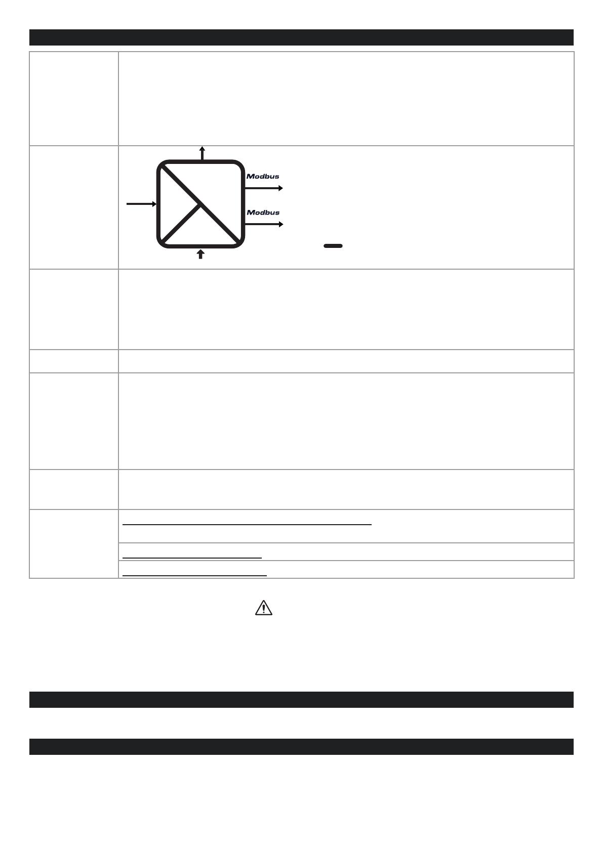
Power
Supply
1500 Vac
11..40 Vdc / 19..28 Vac (IDC10)
ETH
USB
Comm.
Comm. RS485
RS485/232
(IDC10)
The device may only be powered by a power supply unit with a limited energy electric circuit max.
40Vdc / 28Vac Max output in accordance with CAN/CSA-C22.2 No. 61010-1-12 / UL Std. No. 61010-1 (3rd Edi-
tion) chapter 6.3.1/6.3.2 and 9.4 or class 2 according to CSA 223/UL 1310.
ATTENTION
MI00369-8-EN INSTALLATION MANUAL 4/4
INSTALLATION REGULATIONS
The module has been designed for vertical installation on a DIN 46277 rail. For optimal operation and long life,
adequate ventilation must be provided. Avoid positioning ducting or other objects that obstruct the ventilation slots.
Avoid mounting modules over heat-generating equipment. Installation in the bottom part of the electrical panel is
recommended.
SETTING THE DIP-SWITCHES
RS232/RS485 SETTING: RS232 or RS485 conguration on terminals 10-11-12 (serial port 2)
SW2
1 ON RS232 ACTIVATION
0 OFF RS485 ACTIVATION
SETTINGS OF FACTORY PARAMETERS
This procedure returns the IP to the factory one (192.168.90.101) and the Web Server/
FTP server access credentials to user: admin and password: admin.
1. Turn the module off and set all eight SW1 DIP-switches to ON.
2. Turn on the module and wait 10 seconds.
3. Turn the module off and set all eight SW1 DIP-switches to OFF.
KEY
1 ON
0 OFF
These are open-type devices and intended for installation in an end enclosure / panel offering mechanical pro-
tection and protection against spread of re.
ATTENTION
IDC10 CONNECTOR
RS485 GND
RS485 A
RS485 B
Power Supply AC / +
Power Supply AC / -
IDC 10
1
The illustration shows the meanings of the various IDC10
connector pins if signals are to be sent via them directly.
ELECTRICAL CONNECTIONS
CAUTION
To meet the electromagnetic immunity requirements:
- use shielded signal cables;
- connect the shield to a preferential instrumentation earth system;
- separate shielded cables from other cables used for power installations (transformers, inverters, motors, etc...).
10
11
12
GND
A (+)
B (-)
10
11
12
GND
RX
TX
1
2
3
Tens. aus.
Vac/Vdc
Vac/Vdc
POWER SUPPLY SERIAL PORT 2: RS485
SW2 = OFF
SERIAL PORT 2: RS232
SW2 = ON
Use only copper or copper-clad aluminium or AL-CU or CU-AL conductors
ATTENTION
  • Page 1 1
  • Page 2 2
  • Page 3 3
  • Page 4 4

Seneca Z-KEY User manual

Type
User manual

Seneca Z-KEY is a compact and versatile device designed to provide secure and reliable communication solutions in industrial environments. With its robust design and advanced features, the Z-KEY offers a range of possibilities for data transmission, remote monitoring, and control applications. Here are some key capabilities of the Z-KEY:

  • Data Transmission: The Z-KEY supports various communication protocols, including Profinet, RS485, and Ethernet, enabling seamless data exchange with PLCs, sensors, and other devices.

  • Remote Monitoring: Access real-time data and monitor system status remotely using the integrated web server. This allows for proactive monitoring and troubleshooting, reducing downtime and improving efficiency.

Ask a question and I''ll find the answer in the document

Finding information in a document is now easier with AI