Page is loading ...

Eaton’s Cooper Controls Business
203 Cooper Circle
Peachtree City, Georgia 30269
www.coopercontrol.com
Installation Instructions
Model # VNLW-P-1001-MV-N-W
Model # VNLW-P-1001-MV-N-V
Model # VNLW-P-1001-MV-N-LA
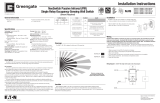
NeoSwitch Passive Infrared (PIR) Single Relay
Vacancy Sensing Wall Switch with Night Light
(Neutral Required)
• Readallinstructionsonbothsidesofthis
sheetfirst
• InstallinaccordancewithALLlocalcodes
• Forindooruseonly
General Information
Technology:PassiveInfrared(PIR)
Electrical Ratings:
120VAC:
• Incandescent/Tungsten–Max.load:6.7amps,
800W,50/60Hz
• Fluorescent/Ballast–Max.load:10amps,1200W,
50/60Hz
MotorLoad:¼HP@125VAC
277VAC:
• Fluorescent/Ballast–Max.load:9.8amps,
2700W,50/60Hz
Ballast Compatibility:Compatiblewithmagneticand
electronicballasts
No Minimum Load Requirement
Time Delays:Self-Adjusting,15seconds/test,1,5,15,
20,30minutes,1hour,2hours
Coverage:Majormotion–1000sq.ft.
Minormotion–300sq.ft.
Operating Environment:
• Temperature:32°F–104°F(0°C–40°C)
• RelativeHumidity:20%to90%Non-condensing
Housing:Durable,injectionmoldedhousing.
PolycarbonateresincomplieswithUL94VO.
Size:
• MountingPlate/StrapDimensions:
4.195"Hx1.732"W(106.553mmx44mm)
• ProductHousingDimensions:2.618"Hx1.752"
Wx1.9"D(66.5mmx44.5mmx48.26mm)
LED Indicators:RedLEDindicatesPIRdetection;
AmberLEDnightlight.
Specifications
Description
ThePassiveInfrared(PIR)SingleRelayVacancySensingWallSwitchwithNightLightisalightingcontrolandWall
Switchall-in-onethatisusedforenergysavingsandconvenience.
PIR Technology
ThePassiveInfrared(PIR)SingleRelayVacancySensingWallSwitchwithNightLightusesPassiveInfrared(PIR)
sensortechnologiestomonitoraroomforoccupancy.
TheVNLW-P-1001-MV-Nallowsthecontrolofoneloadwithonevacancysensorswitch.
ThelightsareturnedONbypressingtheuniversallyrecognizedlighticonPushbutton.ThelightsstayONaslong
asthesensordetectsmotionintheroom.Whentheroomisvacated,thelightsturnOFFautomaticallyafterapreset
TimeDelayinterval.
A30secondgraceperiodisaddedafterthelightsshutOFFtogivetheoccupanttimetomoveagainincasethe
lightsshutOFF.Thispreventstheoccupantfromhavingtowalk-uptopressthePushbuttontoreactivatethesensor.
ThenightlightactivateswhensensorturnslightsOFF.Thisfeaturecanbedisabled,seeDIPSwitchSettings.
Thesensorincludesself-adaptivetechnologythatcontinuallyadjuststoconditionsbyadjustingsensitivityand
TimeDelayinReal-time.ByadjustingsensitivityandTimeDelayautomatically,thesensorismaximizingthepotential
energysavingsthatareavailableintheparticularapplication.
Location
WheninstallingtheVNLW-P-1001-MV-Ninanewjunctionbox,choosetheswitchlocationcarefullytoprovide
optimumcoverageoftheoccupiedarea.WhenreplacinganexistingWallSwitch,bearinmindthattheremustbeaclear
Line-of-sightbetweenthesensorandtheareatobecovered.AvoidpointingtheVNLW-P-1001-MV-Ndirectlyintothe
hallwaywhereitmaydetectpassers-by.
Installation
TheVNLW-P-1001-MV-Ncanbeinstalledinanystandardsingle
gangbox.Itmaybeinstalledinthesamemannerasanordinary
WallSwitch.
• WiretheVNLW-P-1001-MV-Nasdescribedinthewiringsection.
• MounttheVNLW-P-1001-MV-Ninthejunctionbox.
Wiring
CAUTION: Before installing or performing any service on a Greengate system, the power MUST be turned OFF
at the branch circuit breaker. According to NEC 240-83(d), if the branch circuit breaker is used as the main
switch for a fluorescent lighting circuit, the circuit breaker should be marked “SWD.” All installations should be
in compliance with the National Electric Code and all state and local codes.
NOTE REGARDING COMPACT FLUORESCENT LAMPS: The life of some compact fluorescent lamps (CFLs) is
shortened by frequent automatic or manual switching. Check with CFL and ballast manufacturer to determine the
effects of cycling.
1.MakesurepoweristurnedOFFatthebranchcircuitbreaker.
2.Wireunitsasshowninwiringdiagramsperapplicablevoltagerequirements.
3.MountunittoWallBox.
4.TurnpowerbackONatthebranchcircuitbreakerandwait2minutesfortheunittostabilize.
5.Makenecessaryadjustments.(SeeCheckoutandAdjustmentssection)
6.InstallWallSwitchplate.
LOAD
120/277 VAC
BLACK
BLUE
NEUTRAL
GROUND
GREEN
WHITE
Wiring Diagram 1: 120/277 VAC single level single circuit wiring diagram
,
36
20
,
Maximum coverage area may
vary somewhat according to room
shape and the presence of obstacles.
8
,
Minor Motion, IR
Major Motion, IR
Coverage
TheVNLW-P-1001-MV-Nisdesignedforofficesupto300squarefeet.
P/N 9850-000353-01
LOAD 1
BLACK
BLUE
NEUTRAL
GROUND
GREEN
WHITE
120/277 VAC
BLACK
BLUE
GROUND
GREEN
WHITE
TRAVELER
WIRES
THREE-WAY WIRING DIAGRAM:
LIGHTS WILL TURN OFF, WHEN UNIT THAT WAS TURNED
ON LAST AND/OR DETECTED MOTION LAST TIMES-OUT.
Wiring Diagram 2: 120/277 VAC single level single circuit three-way wiring diagram
CAUTION: If a room is wired for two circuits using two separate hot leads, it is very important to connect only one circuit per
relay. Both circuits must be fed from the same phase.

Eaton’s Cooper Controls Business
203 Cooper Circle
Peachtree City, Georgia 30269
www.coopercontrol.com
Printed in Malaysia
Time Delay Adjustments
PeoplewhoremainverystillforlongperiodsoftimemayneedalongerTimeDelaythanthedefaultsettingof10
minutes.Aslongastheself-adjustingfeatureisenabled,theswitchwillrespondtoeachpairofFalse-offswithnonormal
OFFinbetweenbyalternatelymakingslightadjustmentstoeitherTimeDelay(by2minuteincrements)orsensitivity,so
thereshouldbenoneedformanualadjustment.Ifmanualadjustmentisdesired,refertoTimeDelaysettingsinDIP
Switchlegend.
ResetsensorTimeDelaytofactorysettingsbymovingDIPSwitches1,2,and3down.(IfDIPSwitches1,2,and3are
alreadydown,toggleDIPSwitch1outofitscurrentposition,wait3seconds,andthenbacktoitsoriginalposition)
Night Light
UnitisshippedwithNightLightfeaturedenabled.WhensensorturnsthelightsOFF,NightLightisactivated.Todisablethis
featuremoveDIPSwitch7up.
Override
TheOverridesettingallowsthesensortooperateasaserviceswitchintheunlikelyeventoffailure.
1. MoveDIPSwitch8up.
2.ThePushbuttoncanbeusedtomanuallyturnlightsONorOFF.
PIR Sensitivity
1. PressthePushbuttontoactivatesensor.
2
. Standindifferentareasoftheroomandwaveyour
hands.
3. IftheRedLEDdoesnotturnON,checkforany
obstructions.
4. Standstillthreetofourfeetawayfromsensorforfive
seconds.LEDshouldnotturnON.
5. IfRedLEDturnsONwithoutmotionorisconstantly
ONadjustPIRsensitivityto50%bymovingDIP
Switch5up.
Field-of-view outside the space
1. AdjustPIRsensitivityto50%bymovingDIPSwitch
5up.
2. Usenon-reflectivetapestripstocovertheportionsof
thesensorlensthatviewoutsidethespace.
Warranties and Limitation of Liability
DIP Switch Settings Troubleshooting
Pleaserefertowww.coopercontrol.comundertheLegalsectionforourtermsandconditions.
Checkout and Adjustment
1 Minute
Auto*
*Self-Adjusts to
10 min. user mode
Time Delay
DIP Switch
Not Used
PIR Sensitivity OverrideNight Light
Not Used
Default =
15 Minutes
20 Minutes
30 Minutes
5 Minutes
12
DIP Switch Legend
643
5
Full
50%
8
7
Enable
Disable
Disable
Enable
1 Hour
2 Hours
12345678
AdjustmentsshouldbemadewiththeHVACsystemonsothattheinstallerwillbeabletodetecttheeffectof
airflowontheoperationoftheVNLW-P-1001-MV-N.Useonlyinsulatedtoolstomakeadjustments.
Immediatelyafterapplyingpowertothelightingcircuit,waitapproximatelytwominutesfortheswitchtopowerup
andstabilize.
Self-Adjust
Sensorisshippedinself-adjustmode.ThisappliestoTimeDelayandPIRsensitivity.Inpreparationforthe
InstallerTest,theTimeDelayissetto15seconds,afterthesensorisinstalled,poweredONandhasstabilizedthe
unitwillTime-out15secondsafterthelastmotiondetected.Coverageandsensitivitycanbeconfirmedbywatching
theRed(PIR)indicatorLEDonthefrontofthesensor,whilemovingaroundtheroom.
1.WalkaroundtheroomandmonitorLED.
2.Standindifferentpartsoftheroomandwaveyourhands.LEDshouldonlyturnONforonesecondwitheach
motion.(IfLEDdoesnotturnON,gotoInstallerAdjustments–SensitivityAdjustmentSection)
3.Standstillthreetofourfeetawayfromthesensorforfiveseconds.LEDshouldnotturnON.(IfLEDturnsON,
gotoInstallerAdjustments–SensitivityAdjustmentSection)
4
. Walkoutsidetheroomandwait30secondsforthelightstoturnOFF.(IflightsdonotturnOFFgotoInstaller
AdjustmentsSection)
5.Re-entertheroomandmanuallyactivatethesensor.(IflightsdonotturnONgotoTroubleshootingSection)
6.AtthispointyoucanexittheroomandletthesensorTime-out.WhenthesensorTimes-outandisinactivefor
fiveminutes,theunitwillgotoa10minuteTimeDelayusermodesetting.
Note:
ToplaceintoTestMode,toggleDIPSwitch8outofitscurrentposition,wait3seconds,andthenbackintoitsoriginalposition.
ON/OFF Button
PIR Lens
DIP Switches
Red (PIR) LED
Lens glows amber
when night light is
activated
1, 2, and 3
12
3 45678
7 and 8
12
3 456 78
Installer Adjustments
Issue Possible Causes Suggestions
Lights
Will Not
Turn ON
automatically
SensorisinManualONmode
PressPushbutton.IfAutoMode
isdesiredchangeActivationModetoAuto.
SensorwasturnedOFFmanually.IftheSensor
wasturnedOFFmanuallybeforetheTimeDelay
expired,lightswillremainOFFfortheremainder
oftheTimeDelay.
CheckEcoMeterLED,ifLEDisONthisis
anindicationthatthelightswereturnedOFFmanually.
PressthePushbuttontoturnthelightsbackON.
Powerinterruption Checkincomingvoltageand/orwiring.
Lights
Will Not
Turn ON
manually
Powerinterruption Checkincomingvoltageand/orwiring.
If lights will still not turn ON, set sensor to override mode and call Technical Services at 1-800-553-3879
Lights
Will Not
Turn OFF
automatically
Override
MakesuresensorisnotinOverrideMode.
CheckDIPSwitch8tomakesureitisdown.
SelfAdjust
IfsensorisinSelf-AdjustMode.Itmaybe
possiblefortheunittohaveincreasedtheTimeDelayto
a30minutedelay.Ifthelightsdonot
turnOFFafter30minutesfollownextstep.
2hourDelay
MaximumTimeDelayis2hours.CheckDIPSwitches
toverifyDIPSwitchsettings.IflightsdonotturnOFF
atthesetTimeDelay,checknextstep.
PIRactivatedbyheatsourceotherthanoccupant MoveDIPSwitch5up.
Lights
Will Not
Turn OFF
manually
Call
TechnicalServices
If lights will still not turn OFF, call Technical Services at 1-800-553-3879
/


