Page is loading ...

17111
04/19/07 BPL
CONTROL ARM BUSHING INSTALLATION FOR SET # 3-3161
2001 Energy Suspension. All rights reserved. 2001 Energy Suspension. All rights reserved.
CC
May not be reproduced, in any form, or by any means,
without the written consent of Energy Suspension.
May not be reproduced, in any form, or by any means,
without the written consent of Energy Suspension.
1131 VIA CALLEJON, SAN CLEMENTE, CA 92673
R
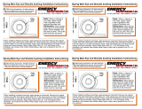
NOTE: TABS ON ORIGINAL SHELL MUST
BE STRAIGHTENED BEFORE REMOVAL.
LOWER CONTROL ARM BUSHING INSTALLATION
For the ease of installation, disassemble the new bushing assembly. Install
shells into both eyes of the control arm. Then stake shell in three places. (As
shown in illustration on LEFT) For best results use a blunt instrument approx.
1/4” wide.
Re-grease I.D Of shells. Re-grease O.D and I.D of bushings. Reinstall bushing
into one shell. Reinstall center sleeve. Install the cross shaft through opposite
shell and through assembled bushing center sleeve. Install washer and nut on
that end of cross shaft. Repeat bushing installation on the other bushing. It will
be necessary to use a piece of tubing or a screwdriver to push center sleeve
into bushing far enough to install the washer and start the nut on the cross
shaft.
UPPER CONTROL ARM BUSHING INSTALLATION
There are no tabs on the upper shells. Follow the same procedure as for the
lower control arm bushing installation, with one exception. After one shell is
installed, the cross shaft must be put into position, then install second shell.
(Most upper shafts will not go through the empty shell)
Check your control arm and make sure it is not bent.
The arm should measure 16-15/16” minimum - 17”
maximum. Outside edge to outside at inboard side. 16 15/16”
/