Page is loading ...

Installation instructions
For set # 3.3101
17444
7/DEC/10 BRH
Updated 8/JAN/03 BRH
Updated 23/JAN/04 BRH
Updated 14/JAN/05 BRH
2005 Energy Suspension. All rights reserved.2005 Energy Suspension. All rights reserved.
CC
May not be reproduced, in any form, or by any means,
without the written consent of Energy Suspension.
May not be reproduced, in any form, or by any means,
without the written consent of Energy Suspension.
1131 VIA CALLEJON, SAN CLEMENTE, CA 92673
R
It is recommended that if you are unfamiliar with this type of work that you refer to a
qualified service center specializing in this type of work. It is also recommended that
if you choose to do this work yourself that a factory service manual be obtained for
the proper procedures pertaining to removal, replacement and proper torque
specifications for your vehicle. This instruction set is intended as a guideline for the
safe installation of Energy Suspension’s polyurethane bushings, once you have
removed the factory components from your vehicle.
POLYURETHANE BUSHING INSTALLATION UPPER/LOWER
GENERAL NOTE: Due to the age and manufacturing practices back in
the late 60’s, we have included this specific instruction sheet. It shows the
specific dimensions of the cross shaft and outer width of the control arms
that these polyurethane bushings where designed for. (Pics 1,2) Please
note that our polyurethane bushings are designed with exact tolerances for
fitment. OEM rubber bushings stick out past the end of the sleeve because
as the bolts are tightened down the rubber squishes into place. Keep this in
mind as you are taking your measurements.
UPPER CONTROL ARM CROSS SHAFT & BUSHING
DIMENSIONS
REMOVAL: Before removing old bushing from upper control arm
measure the (outside of shell to outside of shell) distance of the metal
flanges of the shells with the end cap washers removed and record this
dimension for later use. (Pic 2) This is the “relaxed” state of the arm. This
should be the same measurement after the new metal shells are pressed
in. Note the locations of any washers on cross-shaft prior to removal. In
the event your control arm does not match the listed dimensions, more
then likely you have mis-matched parts. NOTE: Some vehicles have their
shells tack welded to the arm, some do not. IF your shells are tack welded,
you must grind the welds in order to remove the shell from the arm.
INSTALLATION: To keep from bending the flanges of the arm during
installation of the new shells, use a piece of angle iron or channel cut to the
size of the inside width of the flanges. These flanges must remain parallel
to each other, otherwise the new bushings will bind on the cross-shaft. (Pic
3) Now before installing the shells, the cross-shaft MUST BE in place,
you cannot slide the shaft thru once the shells are installed!! Also, note
any washers and locations that were currently installed on cross
shaft. These washers must be reused. Once the cross-shaft is in place,
install the shells into the arm. NOTE: If your original shells were tack
welded to the arm, you must now tack weld the new shells to the arm in the
correct position. Grease I.D. of shell. Grease bushing and install in the
shell. Grease sleeve and install in bushing. TECH NOTE: Depending on
the condition, usage, and age of your cross shaft fasteners, it is
recommended that you replace them with grade 8 or higher hardware.
Stretched bolts are a major cause of them coming loose. Use red lock tight
thread fastener adhesive on fasteners. Re-torque hardware to factory
specifications.
LOWER CONTROL ARM
REMOVAL: Before removing old bushing from lower control arm measure
the (outside of shell to outside of shell) distance and record this dimension
for later use. Measure the inside width of both flanges. (Pic 4) You will
need to find something to put between the flanges before pressing out the
old bushings. This is to keep from bending and distorting the control arms.
Distorting the arms will stretch the metal and oval the eyes. The
eyes/flanges of the control arm need to remain parallel and inline to each
other for proper fit upon installation. Use either metal channel, tubing, or
thick wall PVC tubing for spacers, it’s easiest to work with the PVC. (Pic 4)
INSTALLATION: Now install just the shell into the arm. Grease I.D. of
shell. Grease bushing and install in shell. Grease sleeve and install in
bushing. Re-torque to hardware to factory specifications.
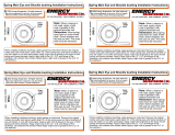
Upper cross shaft
If you need to replace old hardware, use grade 8
bolts and lock washers with red thread locker to
prevent any chance of them backing out.
Ø.671
8.375”
This set was made for a cross shaft with
these dimensions.
1
Upper Control Arm
With the end cap washers removed,
measure the outside width of shell to
shell before pressing out old bushings.
At this relaxed state the measurement
is approximately 11” ± 1/16”
2
Upper Control Arm
9-11/16”
inside
width of
flanges.
The upper arm needs
support between the
flanges when pressing
the new shells in. The
inside width of flanges
is 9-11/16” ± 1/16”.
Support tube
over shell
Spacer tube
Shell
3
Lower Control Arm
A spacer must be used to keep the flanges
parallel when pressing out the old bushings and
pressing in the new shells.
Prior to removing O.E.
rubber bushing, measure
the inside width of flanges
for size of spacer.
4
/