Ridetech StreetGRIP Suspension System for 1970-1981 Camaro & Firebird Installation guide

Type
Installation guide

Ridetech StreetGRIP Suspension System for 1970-1981 Camaro & Firebird gives you excellent ride and handling with dual rate coil springs, Delrin control arm bushings, larger Delrin-lined sway bars, and a taller upper ball joint for your classic F-Body. This kit is designed to work together as a system to improve your car's performance and handling. With its easy installation and lifetime enjoyment, you'll be able to enjoy the benefits of this system for years to come.

Ridetech StreetGRIP Suspension System for 1970-1981 Camaro & Firebird gives you excellent ride and handling with dual rate coil springs, Delrin control arm bushings, larger Delrin-lined sway bars, and a taller upper ball joint for your classic F-Body. This kit is designed to work together as a system to improve your car's performance and handling. With its easy installation and lifetime enjoyment, you'll be able to enjoy the benefits of this system for years to come.

1812-482-2932
Installation
Instructions
Recommended Tools
www.ridetech.com
Table of contents
Page 2............. Major Components and Hardware List
Page 3............. Getting Started
Page 4-12........ Delrin Bushings
Page 13-14...... Tall Upper Ball Joint
Page 15........... Front Dual Rate CoilSpring
Page 16-18...... Front Sway Bar
Page 19-23...... Composite Leaf Springs & Delrin Bushings
Page 23-26...... Front and Rear HQ Series Shocks
Part # 11175010 - 1970-1981 GM F-Body StreetGrip
1970-1981 GM F-Body Street Grip
Installation Instructions
Front Components
11179590 Delrin Control Arm Bushings
90000913 Tall Upper Ball Joint
11172350 Front Dual Rate CoilSprings
22159847 Front HQ Series Shocks
11179120 Front Sway Bar
Rear Components
11174799 Composite Leaf Springs
11175399 Delrin Leaf Spring Bushings
22199847 Rear HQ Series Shocks
The majority of the StreetGrip components will be installed together. For example,
the Front CoilSprings, Ball Joint, Control Arm Bushings and Shocks will be installed in
conjunction with each other. On the rear, the CoilSprings and Shocks will be installed in
conjunction with each other. The Sway Bars will, typically, be installed after the rest of
the components are installed.
REV6 2/20/23
2
www.ridetech.com
Installation
Instructions
Major Components .....In the box
Part # Description QTY
56480700/56538800 Front CoilSprings 2
90002907 Rear Leaf Springs w/ Delrin Bushings & Inner Sleeves Installed 2
90002498 Upper Leaf Spring Clamp Plate 2
90002499 Lower Leaf Spring Clamping Plate 2
90000913 Tall Upper Ball Joint 2
90000896 Lower Ball Joint
90002517 Delrin Bushing Outer Shell - Upper Control Arm 4
11179590 Delrin Control Arm Bushing Kit 1
Front & Rear Shocks
986-10-043 5.25” Stroke Stud Top Shock - Front 2
70011139 5/8” ID Shock Bushing (Installed in Shock) - Front & Rear 4
90002068 Wide T-bar (Installed in Shock) - Front & Rear 4
70011140 Stud Top Bushing - Front 8
70011141 Stud Top Bushing Washer - Front 8
99372006 3/8”-24 Jam Nut - Front 8
986-10-050 8.35” Stroke Trunnion Top Shock - Rear 2
11179120 Front Swaybar Kit 1
90002496 Leaf Spring Shackle Plates 4
70012428 Frame Shackle Bushing 4
90000526 Frame Shackle Inner Bushing Sleeve 2
99501006 1/2”-13 x 3 1/2” Hex Bolt - Lower Control Arm 4
99501035 1/2”-13 x 5” Hex Bolt - Leaf Spring Bushings 6
99502009 1/2”-13 Nylok Nut - Lower Control Arm & Leaf Spring Bushings 10
99561010 9/16”-12 x 3 1/2” Hex Bolt - Lower Control Arm 4
99562006 9/16”-12 Nylok Nut - Lower Control Arm 4
99371050 3/8”-16 x 1 1/2” Conical Bolt - Front Leaf Mount 6
99372009 3/8”-16 U-Nut - Front Leaf Mount 6
99373005 3/8” Split Lock Washer - Upper Control Arm Bolts 4
3812-482-2932
Installation
Instructions
Getting Started......... Getting Started.........
Congratulations on your purchase of the Ridetech StreetGrip Kit. This system has been designed to give
your Car excellent ride and handling along with a lifetime of enjoyment. Some of the key features of this
Kit: Dual Rate CoilSprings, Delrin Control Arm Bushings, Larger Sway Bars with Delrin Liners and a Taller
Upper Ball Joint.
The majority of the StreetGrip Components will be installed together. For example, the Front
CoilSprings, Ball Joint, Control Arm Bushings and Shocks will be installed in conjunction with
each other. On the rear, the CoilSprings and Shocks will be installed in conjunction with each
other. The Sway Bars will, typically, be installed after the rest of the components are installed.
Front Suspension
Rear Suspension
The rear components that will be installed are; rear Composite Leaf Springs, Delrin Leaf Spring
Bushings, and rear HQ Series Shocks. The Composite Leaf Springs and Delrin Leaf Spring Bushings
will be installed at the same time. The Delrin Leaf Spring Bushings are preinstalled in the Leaf
Springs.
The front components that will need to be installed are: Control Arm Bushings, Upper Ball Joints,
Shocks, and CoilSprings. The Sway Bar can be installed anytime after the rest of the front
suspension is complete.
If you have never done this type of work before, we recommend getting a Factory Service Manual
for proper procedures of disassembly and reassembly of the components for your car.
Hardware Kit ..........#99010062
The StreetGrip Kit is supplied with a hardware kit. This hardware kit contains individual bags
for the different kits within the main kit. The bags are labeled to help determine the correct
hardware for the installation of the specific kits. The instructions will aid you in selecting the
correct hardware for each component. The bags included in this kit are:
Front Sway Bar Kit
Control Arm Kit
Leaf Spring Kit
Anytime you change suspension components, you should have the car alignment checked.
Suggested Alignment Specs:
Camber: Street: -.5 degrees
Caster: Street: +3.0 to + 5.0 degrees
Toe: Street: 1/16” to 1/8” toe in
Alignment Specs
4
www.ridetech.com
Installation
Instructions
Recommended Tools
www.ridetech.com
Table of contents
Page 5............. Included Components and Hardware List
Page 6............. Bushing & Sleeves Deminsions
Page 7............. 70-74 & 75-79 Upper Control Arm Bushings
Page 8............. 80-81 Upper Control Arm Bushings
Page 9............. 70-72 Lower Control Arm Bushings
Page 10............ 73-74 Lower Control Arm Bushings
Page 11............ 75-81 Lower Control Arm Bushings
Page 12............ Bushing Installation
Part # 11179590 - 1970-1981 F-Body Delrin Control Arm Bushings
1970-1981 F-Body Delrin Control Arm Bushings
Installation Instructions
IF YOUR CAR IS HAS AN OVAL BUSHING IN THE LOWER CONTROL ARM, IT WILL BE
NECESSARY TO PURCHASE CONTROL ARMS THAT UTILIZE 2 ROUND BUSHINGS.
Ridetech has a Bushing Removal/Installation tool to help simplify the procedure, #85000009.
REV1 9/1/20
5812-482-2932
Installation
Instructions
Major Components .....In the box
Part # Description QTY
70012383 Upper Control Arm Bushing Outer Shell 4
70012385 Lower Control Arm Bushing Outer Shell 2
70012386 Lower Control Arm Bushing Outer Shell 2
70012384 Upper Control Arm Bushing Outer Shell 4
70012387 Lower Control Arm Bushing Outer Shell 2
70012420 Delrin Upper Control Arm Bushing - Upper 4
70012421 Delrin Upper Control Arm Bushing - Upper 2
70012422 Delrin Upper Control Arm Bushing - Upper 2
70012423 Delrin Lower Control Arm Bushing - Lower 2
70012424 Delrin Lower Control Arm Bushing - Lower 2
70012425 Delrin Lower Control Arm Bushing - Lower 2
90002522 Upper Bushing Inner Sleeve 4
90002523 Upper Bushing Inner Sleeve 2
90000516 Lower Bushing Inner Sleeve 4
90000517 Lower Bushing Inner Sleeve 4
90002263 Red Loctite 1
Part # Description Usage QTY
99501006 1/2”-13 x 3 1/2” Hex Bolt Lower Control Arm to Frame 4
99502009 1/2”-13 Nylok Nut Lower Control Arm to Frame 4
99373005 3/8” Split Lockwasher Upper Control Arm Shaft Bolts 4
99561010 9/16”-12 x 3 1/2” Hex Bolt Lower Control Arm to Frame 4
99562006 9/16”-12 Nylok Nut Lower Control Arm to Frame 4
Getting Started.........
The Front Control Arms will need to be removed from the car. Refer to the Factory Service Manual for
disassembly procedure.
This F-Body Bushing Kit contains: 3 different size Upper Control Arm Bushing Assemblies and 3 different size
Lower Control Arm Bushing Assemblies. If your upper control arm has a Bushing with an outer sleeve that
has raised dimples in it to space the bushing out, the new shell doesn’t stick out, but does use a Bushing with
a THICKER flange. The Outside Diameter of the Bushing, in the area that goes into the Control Arm, is the
difference between the 3. Be sure to match the correct diameters with the correct locations. The lowers
can have either a 1/2” or 9/16” ID Inner Sleeve. Both are supplied in the kit. The Chart on the next page
will assist you in selecting the correct bushings to use. The chart has the deminsions of the shells, bushings
and inner sleeves, along with the year ranges they fit. Pages 4-7 contain scale drawings of the bushings and
sleeves. Use these pages to help you determine the correct size bushings and quantities for your installation.
MAKE SURE YOU ARE USING THE CORRECT SECTION FOR YOUR CAR’S YEAR.
6
www.ridetech.com
Installation
Instructions
Bushing & Sleeve Dimensions
OUTER BUSHING SHELLS
QTY Part # A B C YEAR FITMENT & QTY
USED
UPPER INNER SLEEVES
4 90002522 .818 .688 1.800 70-74 (4), 75-79 (2), 80-81(2)
2 90002523 .818 .688 2.109 75-79 (2), 80-81 (2)
LOWER INNER SLEEVES
4 90000516 .750 .500 2.375 70-74 (4)
4 90000517 .750 .562 2.375 75-81 (4)
BUSHING DIMENSIONS
QTY Part # A B C D E YEAR FITMENT & QTY
USED
UPPER BUSHINGS
4 70012420 1.720 .320 1.123 .808 1.610 70-74 (4), 75-79 (2)
2 70012421 1.720 .312 1.213 .808 1.710 80-81 (2)
2 70012422 1.920 .512 1.213 .808 1.690 75-79 (2), 80-81 (2)
LOWER BUSHINGS
2 70012423 2.330 .172 1.163 .740 1.730 70-72 (2), 73-74 (2)
2 70012424 2.330 .208 1.453 .740 1.850 70-72 (2), 73-74 (2),
75-79(2), 80-81 (2)
2 70012425 2.330 .180 1.706 .740 2.200 73-74 (2), 75-79 (2),
80-81 (2)
QTY Part # A B C YEAR FITMENT & QTY USED
UPPER OUTER SHELLS
4 70012383 1.230 1.313 1.700 70-74 (4), 75-79 (2)
4 70012384 1.230 1.406 1.800 75-79 (2), 80-81 (4)
LOWER OUTER SHELLS
2 70012385 2.100 1.359 1.800 70-72 (2), 73-74 (2)
2 70012386 2.100 1.656 2.000 70-72(2), 73-74 (2), 75-79(2),
80-81 (2)
2 70012387 2.100 1.891 2.200 73-74 (2),75-79 (2), 80-81 (2)
A
B
CUPPER
SHELL
A
B
CLOWER
SHELL
INNER SLEEVES
AB
C
INNER
SLEEVES
The 73-74 has 2 possibilities for the Front Bushing of the Lower Control
Arm. The 2 possibilities are in BOLD in the chart.
The 73-74 has 2 possibilities for the Front Bushing of the Lower Control
Arm. The 2 possibilities are in BOLD in the chart.
A
B
C
D
E
A
B
C
D
ELOWER
BUSHING
UPPER
BUSHING
7812-482-2932
Installation
Instructions
70-74 & 75-79 UPPER DELRIN BUSHINGS
1.313O
1.70O
1.23
.320 1.72
.808O
1.61
O
1.171
.818
O
.688
O1.800
1970-1974 UPPER CONTROL ARM BUSHINGS
4 X 70012383 4 X 70012420 4 X 90002522
1975-1979 UPPER CONTROL ARM BUSHINGS
1.313O
1.70O
1.23
.320 1.72
.808O
1.61
O
1.171
.818
O
.688
O1.800
2 X 70012383 2 X 70012420 2 X 90002522
1.406O
1.80
O
1.23 .5121.92
.808O
1.69O
1.261O
2.109
.688
O
.818O
2 X 70012384 2 X 70012422 2 X 90002523
8
www.ridetech.com
Installation
Instructions
80-81 UPPER DELRIN BUSHINGS
1980-1981 UPPER CONTROL ARM BUSHINGS
2 X 70012421
4 X 70012384
2 X 70012422
.818
O
.688
O1.800
2 X 90002522
2.109
.688
O
.818O
2 X 90002523
.312
1.72
.808O
1.71
O
1.261O
.5121.92
.808O
1.69O
1.261O
1.406O
1.80
O
1.23
9812-482-2932
Installation
Instructions
70-72 LOWER DELRIN BUSHINGS
.172 2.330
.740
O
1.730
O
1.273O
.208 2.300
.740
O
1.526
O
1.828
1.359
O
1.80
O
2.10
1.656
O
2.00
O
2.10 2.375
.750
O
.500
O
1970-1972 LOWER CONTROL ARM BUSHINGS
2 X 70012385 2 X 70012423
2 X 70012386 2 X 70012424
4 X 90000516
10
www.ridetech.com
Installation
Instructions
73-74 LOWER DELRIN BUSHINGS
.172 2.330
.740
O
1.730
O
1.273O
.208 2.300
.740
O
1.526
O
1.828
1.359
O
1.80
O
2.10
1.656
O
2.00
O
2.10
2.375
.750
O
.500
O
2 X 70012385 2 X 70012423
2 X 70012386 2 X 70012424
4 X 90000516
O
2.20O
2.10
2 X 70012387 2 X 70012425
OR
.180 2.330
.740O
2.200O
1.780
1973-1974 LOWER CONTROL ARM BUSHINGS
73-74 can have one of 2 size bushings for the front control arm bushing!
11 812-482-2932
Installation
Instructions
75-81 LOWER DELRIN BUSHINGS
.208 2.300
.740
O
1.526
O
1.828
1.656
O
2.00
O
2.10
2 X 70012386 2 X 70012424
4 X 90000517
O
2.20O
2.10
2 X 70012387 2 X 70012425
.180 2.330
.740O
2.200O
1.780
1975-1981 LOWER CONTROL ARM BUSHINGS
2.375
.750
O
.562
O
Delrin Bushing Installation
There are several different ways that the Bushings can be removed from the Control Arms. If you have an
Air Chisel, a Wide Flat Bit works well. If you don’t have access to an Air Chisel, they can be removed by
first, Drilling out the rubber with a Hand Drill and Drill Bit. With the Rubber removed, distort the Bushing
Shell with a Hammer and Chisel and Knock it out. No matter the process used, the main objective is to
NOT distort the Control Arm.
WE RECOMMEND MARKING DRIVER AND PASSENGER CONTROL ARMS AND CROSS SHAFTS.
ALSO, MARK THE ORIENTATION OF THE CROSS SHAFTS.
1. Measure the Outside Width of the Control Arms and write it down before starting Bushing Removal.
You will use this Dimension to check the Control Arms after the new Delrin Bushings are installed.
12
www.ridetech.com
Installation
Instructions
Delrin Bushing Installation
2. Disassemble the Bushing being installed.
If installing Bushings in the Upper Control
Arm, insert the Cross Shaft before installing
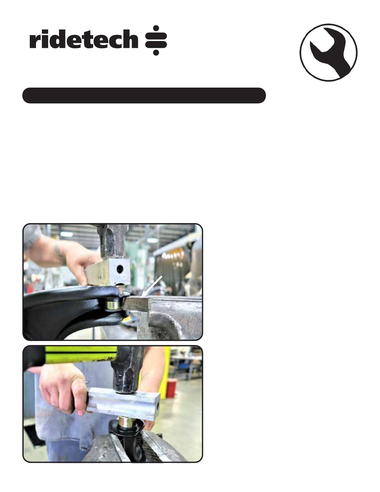
any Bushings. Support the Back Side of the
Flange the Bushing is being Installed in. Use a
STIFF piece of Metal clamped in a Bench Vise for
the Lower Control Arms (Figure 2). The
Upper Control Arm can be supported by either
the same piece of Metal or by the Bench Vise
with the Jaws opened wide enough to let the
Bushing Shell pass through (Figure 3).
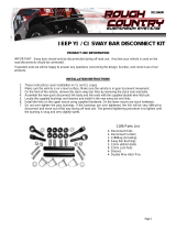
3. Use another Piece of Metal or Strong Wood
to Drive the Outer Shell into the Control Arm
until the Shell stops against the Control Arm.
4. Press the Delrin Bushing into the Bushing Shell
followed be the Inner Sleeve. DO NOT DRIVE IN
WITH HAMMER.
5. Reinstall the Outer Washer using the OEM
Bolt, but replace the Lockwasher with the
supplied Lockwasher. Tighten Hardware to
eliminate any gaps between the Bushings and
Cross Shaft.
6. Reattach Control Arms to Car. Use the OEM
Hardware to attach the Upper and the Supplied
1/2”-13 x 3 1/2” or 9/16”-12 x 3 1/2” Hex Bolts
and Nylok Nuts to Install the Lower Control Arms.
2. LOWER CONTROL ARM
The Cross Shaft must be put in place before installing the Bushing Shells in the Upper Control
Arm.
Just like Bushing Removal, there are several ways the Delrin Bushing Assemblies can be installed. No mat-
ter the method used, the Control Arm needs to be SUPPORTED to keep from distorting the Control Arm.
We recommend cutting spacers to go inside the Control Arms when using a Press to install the Bushings.
We have used several different methods to install the Bushing Assemblies, we are going to cover the one
that worked best for us. When installing the Bushings, the Outer Shell will be installed in the Arm by itself.
Next, Press in the Delrin Bushing, followed by the Inner Sleeve. WE DO NOT RECOMMEND INSTALLING
THE BUSHINGS COMPLETELY ASSEMBLED.
Note: The Delrin is self-lubricating, no lubricant is needed.
Ridetech has a Bushing Removal/Installation tool to help simplify the procedure, #85000009.
METAL
3. UPPER CONTROL ARM
BENCH VISE
13 812-482-2932
Installation
Instructions
www.ridetech.com
Recommended Tools
Table of contents
Page 14....... Included Components & Ball Joint Installation
Part # 90000913 - GM Tall Upper Ball Joint
GM Tall Upper Ball Joint
Installation Instructions
DUE TO THE SHANK OF THE BALL JOINT BEING LONGER, THE BALL JOINT BOOT IS DESIGNED
TO SEAL ON THE BALL JOINT SHANK. IT DOES NOT SEAL AGAINST THE SPINDLE.
14
www.ridetech.com
Installation
Instructions
Major Components .....In the box
Part # Description QTY
90000913 GM Tall Upper Ball Joint 2
Getting Started.........
The Tall Upper Ball Joint is used in the StreetGrip Kit to help correct the Camber Gain. The Camber Gain
on the OEM Suspension is incorrect and the Tall Ball Joint repositions the Upper Control to help improve
the Camber Gain.
The Upper Ball Joint will need to be disconnected from the Spindle. Refer to the Factory Service Manual
for Disassembly.
1.
2.
1. If your Ball Joints are Bolted to the Control
Arms, simply unbolt them. If your car has the
Original Ball Joints, they will be Riveted to the
Control Arms. The Rivets can be removed by
Grinding the Heads off and driving the out
with a Hammer and Punch.
2. Insert the Ball Joint into the Control Arm
from the top side of the Control Arm with
the Ball Joint Pin Sticking down. Attach it to
the Control Arm with the Hardware Supplied
with the Ball Joint. Torque the Hardware to 14
ftlbs. Engage the Ball Joint Pin into the Spindle
and install the Castle Nut Supplied. Torque
the Castle Nut to 60 ftlbs and tighten to align
Cotter Pin Hole. Install Cotter Pin through Hole
and Bend Pins to prevent falling out.
15 812-482-2932
Installation
Instructions
www.ridetech.com
Recommended Tools
Front dual-rate spring will allow the vehicle to transition small road irregularities via a soft spring rate.
When the vehicle compresses the spring far enough (through large bumps or cornering), it transitions to
the firmer spring rate to control the bump or body roll. We have worked closely with Hyperco to develop
custom dual rates to ensure the best ride possible.
The Front Control Arm Bushings and Upper Ball Joint should be installed before installing spring. The
Front Suspension should be assembled with the Lower Ball Joint disconnected from the Spindle.
1. Compress the CoilSpring with an Internal Spring Compressor with the CLOSE COILS TO THE BOTTOM.
2. With the OEM Spring Removed, insert the CoilSpring into the Pocket. SPECIAL ATTENTION NEEDS TO BE PLACED
ON THE LOCATION OF THE ENDS OF THE SPRINGS TO MAKE SURE THEY ARE CLOCKED CORRECTLY . The end of
the CoilSpring will nest into the receiver area of the Control Arm. If you line up the bottom, the top will be correct.
3. While holding the Spring in place, Slowly Jack the Lower Control Arm up until the Lower Ball Joint can be Engaged
into the Spindle. Install the Castle Nut and Torque to 65 ftlbs then tighten as needed to align cotter pin hole. Install
Cotter Pin. Once the Ball Joint is tight, remove the Spring Compressor.
1970-1981 GM F-Body Front CoilSprings
Installation Instructions
Part # 11172350 - 1970-1981 F-Body Front CoilSpring
CoilSpring # 56480700 Installation
REV1 2/20/23
16
www.ridetech.com
Installation
Instructions
Recommended Tools
www.ridetech.com
Table of contents
Page 17......... Included Components and Hardware List
Page 18......... SwayBar Installation
Part # 11179120 - 1970-1981 GM F-Body Front SwayBar
1970-1981 GM F-Body Front SwayBar
Installation Instructions
Hardware Torque Specifications
5/16”-16................. 17 ftlbs
3/8”-16................... 30 ftlbs
REV2 1/24/22
17 812-482-2932
Major Components .....In the box
Part # Description QTY
90001226 Front Sway Bar 1
90002936 End Link Kit 1
90002513 Bushing Strap 2
70015015 Lined Sway Bar Bushing 2
90001254 Bushing Mount Adapter 2
Getting Started.........
Note: This sway bar kit utilizes a anti-friction lining in the sway bar bushing. The lining allows the sway
bar to move freely and quietly in the bushing. No lubrication is required.
Note: The threaded holes in the frame can be either 5/16”-18 or 3/8”-16. Hardware is supplied for both.
1. Jack the vehicle up to a safe working height and support with jack stands. Make sure the jack stands
are stable before working under the car.
2. Remove the stock sway bar.
3. After removing the stock sway bar, determine what size hardware the frame will require.
HARDWARE KIT......99010083
QTY Part Number Description
ADAPTER PLATE
2 99371032 3/8”-16 x 1 1/4” Flat Head
2 99311025 5/16”-18 x 1 1/4” Flat Head
2 99371005 3/8”-16 x 1 1/4” Hex Bolt
2 99311011 5/16”-18 x 1 1/4” Hex Bolt
2 99373002 3/8” Flat Washer
2 99313001 5/16” SAE Flat Washer
2 99373006 3/8” Split Lock Washer
2 99313003 5/16” Split Lock Washer
1 90002263 Red Loctite
QTY Part Number Description
BUSHING STRAP
4 99371065 3/8”-16 x 3/4” Hex Bolt
4 99373002 3/8” Flat Washer
4 99373006 3/8” Split Lock Washer
4. Open the sway bar bushing at the split and
slip it OVER the sway bar. Do this for both
bushings.
4. 5.
6. Slip the Bushing Straps over the Sway Bar
Bushings.
18
www.ridetech.com
6.6.
7. Hold the Frame Plate up to the OEM holes, the
Counter Sunk hole will he positioned over the front
hole with the slot to the rear. Apply Red Loctite to the
Flat Head Bolt. The rear 1 1/4” long bolt uses a Split
Washer and Flat Washer. Torque Hardware.
7.
9. Install the End Links using Diagram 1 as a reference. Install both end links before tightening the end
link hardware. Tighten the end link barrel nut until it is flush with the end of the bolt, and then tighten
it 2 more complete rounds.
10. Torque the SwayBar mounting hardware to 30 ftlbs.
9
8. Slide the SwayBar into position on the car with the
SwayBar arms above the tie rods. Install a 3/8” Lock
Washer & 3/8” Flat Washer on the 3/8”x 3/4” Hex
Bolts. Do NOT Complete tighten the Hardware, it will
be left partially loose until the End Links are installed.
8.
FRONT
FLAT HEAD
SOCKET CAP
SCREW
Diagram 1
Control Arm
6. This kit contains an adpater plate to attach the sway
bar to the frame. Depending on the year of the car, the
hardware size can vary. Before continuing to the next step,
you will need to determine the bolt size required for your
installation. The threaded holes in the frame can be either
5/16”-18 or 3/8”-16. Hardware is supplied for both.
OEM
MOUNTING
HOLES
19 812-482-2932
Installation
Instructions
www.ridetech.com
THESE COMPOSITE LEAF SPRINGS WILL ACCEPT OEM LEAF SPRING BUSHINGS. THE RIDETECH
STREETGRIP KIT HAS THE DELRIN LEAF SPRING BUSHINGS (11165399) PREINSTALLED FOR
MAXIMUM PERFORMANCE.
IT IS VERY IMPORTANT THAT NOTHING COMES IN CONTACT WITH
THE COMPOSITE LEAF SPRINGS.
Recommended Tools
Table of contents
Page 20........... Included Components and Hardware List
Page 20-23...... Leaf Spring Installation
Part # 11174799 - 1970-1981 F-Body Composite Leaf Springs
1970-1981 F-Body Composite Leaf Springs
Installation Instructions
20
www.ridetech.com
Installation
Instructions
Major Components .....In the box
Part # Description QTY
90002907 Leaf Spring Blade Assembly w/70012426, 70012427, & 90000526 installed 2
90002498 Lower Leaf Spring Clamping Plates 2
90002499 Upper Leaf Spring Clamping Plate 2
70012428 Delrin Rear Shackle Frame Bushing 4
90000526 Inner Bushing Sleeve 2
90002496 Shackle Plate 4
99371050 3/8”-16 x 1 1/2” Conical Bolt 6
99372009 3/8”-16 U-Nut 6
Getting Started.........
IT IS VERY IMPORTANT THAT NOTHING COMES IN CONTACT WITH THE LEAF SPRING.
1. Jack the car up and support it by the frame rails. You will need to raise and lower the rear differential with
a jack to ease installation. With the car supported by the frame, put the jack underneath the rear end housing
and raise the jack up just enough to support the differential. Disconnect the bottom of the shock and remove
the rear leaf springs. Retain the OEM hardware. The OEM frame bushings will need to be removed and all
debris removed from the holes to ease installation of the bushings.
2. The Shackle Plates and Hardware can be used to push the rear bushings into the frame location. Start the
bushings into the frame and insert a 1/2”-13 bolt into a shackle plate. Insert the bolt/shackle plate into the
bushing and install a second shackle plate on the bolt sticking through the bushing. Install a 1/2”-13 nut and
tighten until the bushings bottom out on the frame. Remove the shackle plates and install the inner sleeve.
3. 3. Bolt the LARGE BUSHING END of the
Composite Leaf Spring into the OEM front leaf
spring mount using a 1/2”-13 x 5” Hex Bolt
and 1/2”-13 Nylok Nut. The Bolt must be in-
stalled with the threads pointing to the OUT-
SIDE of the car. Diagram #4 is the correct.
NOTE: Front spring pocket must be re-
moved from car before installing new
springs. New Hardware is supplied in kit.
HEX NUT
99501035 1/2”-13 x 5” Hex Bolt 6
99502009 1/2”-13 Nylok Nut 6
Hardware Bag - Leaf Spring Kit
  • Page 1 1
  • Page 2 2
  • Page 3 3
  • Page 4 4
  • Page 5 5
  • Page 6 6
  • Page 7 7
  • Page 8 8
  • Page 9 9
  • Page 10 10
  • Page 11 11
  • Page 12 12
  • Page 13 13
  • Page 14 14
  • Page 15 15
  • Page 16 16
  • Page 17 17
  • Page 18 18
  • Page 19 19
  • Page 20 20
  • Page 21 21
  • Page 22 22
  • Page 23 23
  • Page 24 24
  • Page 25 25
  • Page 26 26

Ridetech StreetGRIP Suspension System for 1970-1981 Camaro & Firebird Installation guide

Type
Installation guide

Ridetech StreetGRIP Suspension System for 1970-1981 Camaro & Firebird gives you excellent ride and handling with dual rate coil springs, Delrin control arm bushings, larger Delrin-lined sway bars, and a taller upper ball joint for your classic F-Body. This kit is designed to work together as a system to improve your car's performance and handling. With its easy installation and lifetime enjoyment, you'll be able to enjoy the benefits of this system for years to come.

Ask a question and I''ll find the answer in the document

Finding information in a document is now easier with AI