Page is loading ...

Model SCS-104INT Line Card
Description
The SCS-104INT provides four digital dialer (DD) lines and a network
connection for communication to DMP panels. Each card includes one
shielded eight-pin modular connector (J1) for the Ethernet network
connection. This allows the SCS-1R Receiver to accept alarm and
system messages over a network from DMP panels. Each card also
includes a non-shielded eight-pin modular connector (J3) that supports
up to four digital dialer lines, when connected to a standard RJ61 jack.
An optional PC software application, SCS-CTM Check-in Table Manager,
is available to backup the SCS-104INT records of all supervised network
accounts for up to 32 different SCS-104INT line cards. The SCS-CTM
program is compatible with SCS-104INT Version 100 or higher. For
complete operation information, refer to the SCS-CTM User’s Guide
(LT-0940). Contact DMP Customer Service to purchase a copy of the SCS-
CTM Check-in Table Manager software.
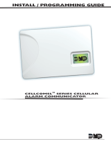
Installing the SCS-104INT
Install the SCS-104INT in any one of the SCS-1R
positions with the card puller in the up position.
Connect the 10-position line card cable from the
SCS-150 processor card. The line card number
is determined by the processor card cable it is
connected to.
THE LIGHT BROWN (PIN 1) WIRE OF THE FLAT CABLE
CONNECTOR MUST FACE UP ON THE LINE CARD.
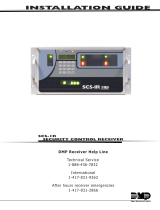
Connecting the Phone Lines
Connect the phone line cable from the
line card to the customer supplied RJ61
jacks. Use a standard 103J voice grade
(analog) line. Cables can be fed through
the slot in the receiver back plate.
Maximum line impedance is 100 Ohms.
Connecting the Network
Connect an IP network cable between
the J1 Ethernet connector on the front of
the line card and the network LAN/WAN
connection. Maximum line impedance is
100 Ohms. The SCS-104INT automatically
communicates UDP or TCP with DMP
panels and automatically communicates with encrypted panels using 128-bit or 256-bit AES Encryption.
Note: 256-bit encrypted messages sent to the SCS-1R receiver from an XR550E International Control Panel Version 104
or higher software will only communicate with SCS-104INT Line Cards with Version 102 or higher software.
Phone Line Monitor
The SCS-104INT monitors incoming phone line voltage. During a loss of phone line voltage, the SCS-104INT sends a
Warning: Phone Line Trouble message (System Message 153) to the host automation or LCD display.
Power Monitor LED
The green LED labeled PWR turns on when the power supply on the line card is working properly.
SCS-104INT Line Card
Red
Black
J8
Ethernet J1
Phone
Line J3
Power
DTR
Line 1
Line 2
Line 3
Line 4
Line Card Connector
SCS-150INT Receiver
Processor Card
Rack-Mounting
holes
SCS-104INT Line Cards
SCS-150INT Network
Connection
INSTALLATION GUIDE

800-641-4282
INTRUSION • FIRE • ACCESS • NETWORKS
www.dmp.com 2500 North Partnership Boulevard
Designed, Engineered and
Assembled in U.S.A. Springeld, Missouri 65803-8877
LT-1207INT © 2016 Digital Monitoring Products, Inc.
16214
EN 61000-3-3 Limitation of Voltage Fluctuations & Flicker
in Low-Voltage Supply Systems for Equip.
with Rated Current Less Than or Equal to
16A per Phase & Not Subject to Conditional
Connection
EN 61000-6-4 Generic Standards - Emission Standard for
Industrial Environments
ETSI ES 203 021-1 Access and Terminals (AT); Harmonized basic
V2.1.1 (2005-08) attachment requirements for Terminals for
connection to analogue interfaces of the
ETSI ES 203 021-2 Telephone Networks
V2.1.1 (2006-01)
ETSI ES 203 021-3
V2.1.1 (2006-01)
SCS-104INT LED Indicators
The SCS-104INT provides eight LEDs on the card. The table below describes the LED operation.
LED Description
Solid Flashing Off
POWER Power On N/A Power Off
DTR Data Terminal Ready N/A Processor is nearly full
LINE 1 Connected (off hook) Ringing Idle
LINE 2 Connected (off hook) Ringing Idle
LINE 3 Connected (off hook) Ringing Idle
LINE 4 Connected (off hook) Ringing Idle
LINK Indicates a valid Network connection
Indicates a valid Network connection
No Connection
LINK SPEED Connected at 100 Base-T N/A Connected at 10 Base-T
SCS-104INT Programming
The SCS-104INT is programmed through the SCS-150 Receiver Processor Board using a Membrane keypad or Browser
programming. For more information see the SCS-1R Installation Guide (LT-1037INT).
SCS-104INT Software Update
Updating the software for SCS-104INT Receiver Line Cards can be done using Remote Link Version 1.61 or higher.
Use the following steps to perform the SCS-104INT update:
1. Remove the SCS-104INT Line Card from the SCS-1R
Receiver.
2. Connect a Model 399 Programming Cable to the PROG
header (J8) on the line card and to a computer with
Remote Link.
3. Place a shorting clip across the 2 pins of the LOAD (J18)
header.
4. Reinstall the SCS-104INT Line Card into the SCS-1R
Receiver to power up line card.
5. Open Remote Link and select System > Remote Update
from the drop-down menu.
6. In the Remote Update window, use the browse button
to nd the SCS104.RU software update le on your
computer's hard drive. Remote Link automatically recognizes the update for the SCS-104INT and allows you to select
the COM port where the line card is connected.
7. Select Update. After the update is complete, remove the SCS-104INT from the receiver and disconnect the 399 cable
and remove the shorting clip from the LOAD header. Reinstall the Line Card to begin normal operation.
Note: Position 1 on dip switches (S1) must be up (on) to enable International operation.
International Certications
Intertek (ETL)
Security Grade 3
Environmental Class: II
EN 50130-4 EMC Product Family Standard:
Immunity Requirements for
Components of Fire, Intruder
and Social Alarm Systems
EN 50130-5 Environmental Standards
EN 50131-1:2006+A1 Intrusion and hold-up systems
EN 50136-1 Alarm Transmission Systems and
Equipment
EN 50136-2:2013 Supervised Premises Transceiver
EN 50136-3 Receiving Centre Transceiver
EN 61000-3-2 Limits - Limits for Harmonic
Current Emissions (Equip. Input
Current Up To and Including 16A
per Phase) A1 & A2 July 1, 2009
/