Page is loading ...

INSTALLATION GUIDE
SCS-105 SDLC Single Line Service Receiver
Features
• Multiplex or digital dialer operation
• Supports up to 128 multiplex accounts
• Supports up to 65,535 digital dialer accounts
• Built-in processor watchdog
• Highly visible communication status LED indicators
• Output to Remote Link™, System Link™, or host computer
• Audible line monitor with volume control
• 2 or 4-wire multiplex operation
Description
The SCS-105 Single Line Service Receiver provides a control interface between a host computer and one or more DMP
panels. The SCS-105 allows users with DMP Remote Link™ or System Link™ software to remotely program and perform
control functions on control panels without using a DMP SCS-1R Security Control Receiver. The SCS-105 comes preset
for standard 2-wire digital dialer operation and can easily be congured to work with 2-wire or 4-wire multiplex
systems.
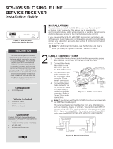
LT OL CD RD TD ST
RESET
VOLUME
MODEL SCS-105
Single Line
Service Receiver
Figure 1: Front Faceplate
Installation
The best place to install the SCS-105 is near your Remote Link™
or System Link™ computer. This allows you to monitor the
communication status LEDs while receiving or sending transmissions,
and provides easy access to the line monitor volume control.
Cable Connections
Connect the 4-wire phone cable from the appropriate phone jack
into the TELCO port on the rear of the SCS-105.
Connect the 4-wire data cable to the rear HOST port on the SCS-105
receiver. Connect the 25-pin male connector to the convertor cable
using the 25-pin female connector. Finally connect the 9-pin male
connector on the convertor cable to the serial port on the back of
the computer. Refer to Figure 2 for cable connectors.
Note: If you do not wish for the SCS-105 to
pickup incoming calls, call DMP Technical
Support at 1-888-4DMPTEC (1-888-436-7832) or
417-831-9362 between 7 AM to 7 PM Central time
for assistance, or e-mail [email protected].
The serial port selected must be free from
any other devices such as modems, mouse, or
printers. You cannot use COM 1 if you are using
COM 3 for another device. Also, you cannot use
COM 2 if you are using COM 4 for another device.
These COM ports have the same interrupt and
cannot be used together.
4-wire connector to
HOST port on SCS-105
9-pin male connector
25-pin female connector
25-pin male
connector
Convertor
cable
Figure 2: Cable Connectors
HOST
TELCO
TELEPHONE
12VDC
Incoming
Phoneline
To Optional
Telephone
AC/DC Power
Converter
RS-232 to Remote Link, System
Link, or host computer
Figure 3: Rear Connections

Digital Monitoring Products SCS-105 Installation Guide
2
Adding a Telephone
You can also connect a standard telephone to the rear TELEPHONE port of the SCS-105 to be able to call and talk to
a subscriber at the premises prior to any remote operations.
Digital Dialer Mode
The SCS-105 receiver comes congured for 2-wire digital dialer operation and no hardware adjustments are
necessary.
Multiplex Mode
To use the SCS-105 in multiplex mode with multiplex subscriber accounts, you must make some jumper adjustments
on the inside of the receiver.
J3
J6
J2
J5
950-0020
950-0020
Figure 4: Jumper Locations
To congure the SCS-105 for multiplex mode:
1. Remove the two front panel screws
2. Gently slide the circuit board assembly out of the case and place on a non-static surface.
3. Set the jumpers J2 and J5 to MPX.
4. If installing the SCS-105 in a 4-wire multiplex system, set the jumpers J3 and J6 to 4W.
5. Once the jumpers have been set, slide the SCS-105 circuit board assembly back into the case and install the
two front panel screws.
Digital dialer mode must be set for 2-wire only: When changing the SCS-105 from multiplex to digital dialer, make
sure jumpers J3 and J6 are set to 2W.
Power Up
Once you have congured the SCS-105 for the appropriate communication mode and connected the necessary
cables, you are ready to apply power. Remove the twist tie from the AC adaptor cord and insert the plug into the
rear 12VDC jack. Plug the AC adaptor into a nearby unswitched 120VAC outlet.
At power up, the SCS-105 conducts an initialization routine for about ve seconds, after which the green status LED
begins ashing at a rate of once each second. This indicates the receiver is operating normally.
Status LEDs
The SCS-105 provides six status LEDs that allow you to monitor communication between the receiver and the
subscriber’s panel. A description of each LED follows:
LED
Description
Display Denition
LT Line Trouble
Indicates improper phone line voltage or faulty connections. If this LED is lit and you
are experiencing trouble with a panel connection, check the phone line voltages.
OL On Line Indicates the SCS-105 is in an off-hook condition.
CD Carrier Detect Indicates the receiver detects the carrier tone from the panel.
RD Receive Data Indicates the receiver is receiving data from the panel.
TD Transmit Data Indicates the receiver is transmitting data to the panel.
ST Status Flashes when the receiver is operating normally. See Reset Button on page 3.

SCS-105 Installation Guide Digital Monitoring Products
3
Volume Control
You can adjust the volume control to listen to data transmissions between the SCS-105 and DMP panels. For normal
listening levels, set the volume control at about one sixth of a turn clockwise. Turning the volume control fully
counterclockwise silences the SCS-105.
Reset Button
During normal operation, the green status (ST) LED ashes about once every second. If the status LED either comes
on steady or goes out completely the SCS-105 needs to be reset. Follow the steps below to reset the SCS-105
receiver:
1. Place the head of a small slotted screwdriver against the reset button.
2. Lightly press the reset button and hold for about two seconds before releasing.
3. Wait about ve seconds for the SCS-105 initialization routine to end.
Initialization
During initialization, the SCS-105 tests its outputs, built in speaker, and internal circuits. At the end of initialization,
the green LED begins to ash indicating normal operation.
If the green LED does not ash after initialization, remove all cables connected to the SCS-105 except the AC cable
and repeat the reset procedure.
If the SCS-105 still does not function correctly call DMP Technical Support at 1-888-4DMPTEC (1-888-436-7832) or
417-831-9362 between 7 AM to 7 AM Central time for assistance, or e-mail [email protected].
Using the SCS-105 with Remote Link™ and System Link™ Software
If you are using the SCS-105 with DMP Remote Link or System Link software, you must make a few conguration
adjustments to the software before contacting any subscriber accounts. Refer to your Remote Link™ User’s Guide
(LT-0565) or System Link™ User’s Guide (LT-0570) for additional information.
Status LED During Programming
During the conguration of the SCS-105, the ST (Status) LED ashes at a faster than normal rate to indicate
programming of the receiver’s EEPROM memory. Do not remove the receiver’s power supply or reset the receiver
during the programming.
Baud Rate Setting
When using the SCS-105 with Remote Link or System Link, the Baud Rate in the software must be set to 9600 baud.
You can set the baud rate in Remote Link and System Link by selecting System > Congure > Remote Link (or
System Link) > Receiver tab. In the Baud Rate eld, select 9600 from the drop-down menu.
Receiver Key Programming
The SCS-105 is shipped with a blank default receiver key. The receiver key allows you to perform remote connect
operations as the service receiver. You should change the default key to one that is unique to this SCS-105 to restrict
unauthorized remote programming of your subscriber accounts. Refer to the Remote Link™ User’s Guide (LT-0565) or
System Link™ User’s Guide (LT-0570) for additional information.
Answering Machine Bypass Function
If you are contacting a panel that has answering machine bypass capability, the SCS-105 turns on a carrier tone ve
seconds after it nishes dialing the account phone number. The carrier tone is on for approximately 90 seconds
during which the subscriber’s panel will pick up the phone line and allow communication with the Remote Link™ or
System Link™ computer. Requires SCS-105 rmware version 207 or higher.

800-641-4282
INTRUSION • FIRE • ACCESS • NETWORKS
www.dmp.com 2500 North Partnership Boulevard
Designed, Engineered and
Assembled in U.S.A.
Springeld, Missouri 65803-8877
LT-0153 © 2017 Digital Monitoring Products, Inc.
17103
Troubleshooting
Symptom Cause Solution
Receiver does not operate
when connected to Remote
Link or System Link computer.
COM port conict on computer
Make sure the other devices are not on the
same interrupts or IRQs.
Baud rate is not properly set
Congure the Baud rate in Remote Link or
system Link to 9600 Baud.
Bad cable connection
Check connections and the continuity of the
conductors.
Bad data switcher Bypass the data switch.
AC adaptor damaged
Always unplug AC adapter from AC outlet before
removing the plug from the end of the receiver.
Incorrect Windows COM driver
Install correct COM driver from your Windows
install disk.
Cannot connect with panel.
Jumper settings not correctly set Open receiver case and check jumper settings.
Incorrect Account number
Double-check that the account number is
correct.
Panel not programmed properly
In the panel Remote Options programming,
be sure that the Alarm Receiver or Service
Receiver is set to YES.
Telephone attached to
TELEPHONE port does not
work.
Receiver is on-line with a panel Wait until the panel is nished communicating.
Receiver is unplugged
Be sure that all connections are good.
Check the telco line connections and the AC
connection.
Specications
Operating Voltage 12VDC supplied by AC
adaptor
Operating Current 200mA maximum
RS-232 Output 9600 baud
Case Construction Extruded aluminum with
plastic ends
Dimensions 10.4” L x 5.5” W x 1.6” H
Weight 2 lbs.
Compatibility
The SCS-105 is compatible with all DMP Panels.
Accessories
Remote Link Panel Programming Software
System Link End-User Panel Management Software
Command Center Visual Command and Control Software
Alarm Monitoring Alarm Monitoring Software
395 SCS-105 Data Cable
/