Page is loading ...

InstallatIon GuIde
iCOM™ Network Alarm Router &
iCOM-E™ Encrypted Network Alarm Router
Description
The iCOM™ Network Alarm Router and iCOM-E™ Encrypted Network Alarm Router allow DMP Command Processor™
Panels to communicate over an Ethernet or a full-time Internet connection to a DMP SCS-1R Receiver. The iCOM/
iCOM-E are compatible with XR500 panels.
Operating as an interface between the panel and the network, the iCOM or iCOM-E installs inside the panel enclosure
and communicates through a 462N Network Interface Card or connects directly to the panel using the nine-pin serial
connector on J21 as shown in Figure 2.
These instructions apply to both the standard iCOM™ and the iCOM-E™. Please note the specic programming
options for the iCOM-E™ version only and the specic installation steps for the iCOM/iCOM-E and XR500 panel.
iCOM-E™ Description
For High Security applications where the Advanced Encryption Standard (AES) Rijndael Encryption Algorithm is
required or desired, use the iCOM-E™ Encrypted Network Alarm Router. The iCOM-E™ is NIST certied.
Note: The iCOM-E is not compatible with the XR500N, XR500E, or XR2500F panels.
Components
The following components are included:
• iCOM Network Alarm Router OR iCOM-E Encrypted Network Alarm Router
• 2-wire Power Cable
• DMP Model 356-2 Serial Cable
• 4-wire Keypad Programming Cable (to program the iCOM or iCOM-E)
What Else is Needed
Additional equipment needed to install, program, and use the iCOM or iCOM-E:
• DMP 32-character LCD keypad OR a computer with available serial communications port
• Hyperterminal communication (terminal emulation) software or Telnet (if using a computer to program the
iCOM or iCOM-E)
• DMP Model 396 Programming Cable (if using a computer to program the iCOM or iCOM-E)
• Ethernet or full-time Internet connection
• DMP XR500 Command Processor™ Panel and 397 panel-to-iCOM cable
• 461 Interface Adaptor Card for XR500 panels without an available expansion slot
Wiring Notes for XR500 Panels
1. The network cable connected to the iCOM or iCOM-E J4 Network Connector cannot directly leave the building
where the iCOM or iCOM-E is installed. You must connect the cable to another network device, such as a router
or gateway, before establishing an external connection.
2. If you extend the power cable, you must use crimp connectors.
3. Program the iCOM/iCOM-E before plugging the 397 cable into the iCOM/iCOM-E from the RS-232 port, J21.
4. If you are programming the iCOM or iCOM-E with a computer, do not connect 2-wire Power Cable. See
Preparing to Program the iCOM or iCOM-E with a Computer later in this document.

Digital Monitoring Products iCOM™/iCOM-E™ Installation Guide
2
Wiring the iCOM/iCOM-E and 462N Card
See the Wiring Notes above before completing these connection steps.
1. After properly installing the iCOM or iCOM-E in the enclosure, connect the Ethernet cable from your network to
the iCOM or iCOM-E Network Connector (J4).
2. After programming, connect the supplied Model 356-2 Serial Cable to the 462N card J7 connector.
3. Attach the 356-2 cable from the 462N card to the iCOM or iCOM-E J3 Serial Connector.
4. Connect the 2-wire Power Cable to J2 Power Connector.
5. Connect the power cable red wire to terminal 7 on the panel.
6. Connect the power cable black wire to terminal 10 on the panel.
Conguring the 462N Card
To congure the 462N, adjust the jumper settings on the 462N
as shown in Figure 1. Refer to the 462N Network Interface Card
Installation Sheet (LT-0209) for installation and setup instructions.
Note: The XR500 panel does not require the 462N Card, but can
use the 462N card in some installations. For standard XR500
installation, refer to the XR500 panel wiring on the next page.
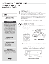
Wiring the iCOM/iCOM-E and XR500 Panel
See the Wiring Notes on the previous page before completing these
steps.
1. After properly installing the iCOM or iCOM-E in the enclosure, connect the Ethernet cable from your network to
the iCOM or iCOM-E to J4 Network Connector.
2. Install a jumper on the top pair of headers next to the letter "R" on J23.
3. Reset the panel using the J16 jumper to activate RS-232 operation.
4. Connect a Model 397 Serial Cable to J21 RS-232 nine-pin connector on the XR500 panel.
5. Connect the 2-wire Power Cable to J2 Power Connector.
6. Connect the power cable red wire to terminal 7 on the panel.
7. Connect the power cable black wire to terminal 10 on the panel.
AC
1234 5 6 7 8 10 11 12 13 14 15 16 17 18 199 20212223242526 2728
+B BELL GND SMK GNDRED YEL GRNBLK Z1 Z2 Z3 Z4 Z5 Z6 Z7 Z8 Z9+ Z9- Z10+ Z10-AC -B GND GND GNDGND
J23
J21
RS-232
XR500
Command Processor™
Panel
R
L
X
J3: Serial
J4: Network
J1: To Keypad for
Programming
J2: To Panel
for Power
Serial Cable
iCOM/
iCOM-E
Black
Red
Power limiting
wiring routing
J6: Expansion
Connector
Figure 2: iCOM™/ iCOM-E™ and XR500 Installation and Power Wiring
Programming for Network Communication
You must program the XR500 for network communication.
1. Reset the panel using the J16 jumper.
2. From the keypad, enter 6653 and press COMMAND.
3. Press the COMMAND key until you reach the Communication programming section. For Communication Type,
Select NET for Network communication.
RXD = NO
TXD = NO
Baud Rate = 9600
J3 = FORCE
J6 = HST
YES NO YES NO
RXD TXD
FORCE CTS DNET HST
EXT
9600
4800
2400
1200
300
J3
J6
J2 J5
J1 J4
Figure 1: 462N Jumper Settings

iCOM™/iCOM-E™ Installation Guide Digital Monitoring Products
3
iCOM or iCOM-E LED Indicators
Refer to Figure 4 for each LED location.
Serial Communication LEDs
Transmit: A ashing green LED indicates the unit
is transmitting serial data to the panel.
Receive: A ashing yellow LED indicates the unit
is receiving its serial data from the panel.
Network LEDs
Error 1 & 2: For DMP internal use only.
Activity: A yellow ashing LED indicates activity
on the network.
Link: A steady on green LED indicates the
communication link to the network is okay.
Preparing to Program the iCOM or iCOM-E
You may program the iCOM or iCOM-E with a DMP 32-character LCD keypad or a computer running Hyperterminal
communication software.
Preparing to Program the iCOM or iCOM-E with a Keypad
To program the iCOM or iCOM-E with a DMP 32-character keypad, set the CURRENT KEYPAD ADDRESS to 1 (one) and
select SUP for the KEYPAD MODE. These options are programmed in the Keypad Options menu. Refer to the keypad
installation sheet for more information. After programming these two settings, follow the steps below.
1. Disconnect the 2-wire Power Cable from the iCOM or iCOM-E J2 Power Connector. See Figures 2 and 3.
2. Disconnect the 356-2 serial cable from the J3 Serial Connector.
3. Connect a DMP 32-character LCD keypad to the J1 Programming Connector.
4. Reconnect the power cable to the J2 Power Connector.
5. The keypad displays iCOM PROGRAMMER or iCOM-E PROGRAMMER. Press the COMMAND key to enter
programming mode.
While programming the iCOM or iCOM-E with a keypad, press the COMMAND key to advance to the next programming
option. To begin entering programming information press any top row Select key. You can return to the previous
programming option by pressing the Back Arrow key.
Note: IP addresses and port numbers may need to be assigned by the network administrator. When entering an IP,
Gateway, or Subnet Mask address be sure to enter all 12 digits and leave out the periods. For example, IP address
192.168.000.250 is entered as 192168000250.
Programming the iCOM or iCOM-E with a Keypad
LOCAL IP ADDRESS
192.168.000.250
Local IP Address
This is the iCOM or iCOM-E IP address. The Local IP Address must be unique and cannot be
duplicated on other iCOM™ Network Alarm Routers or iCOM-E™ Encrypted Network Alarm
Routers. When DHCP is set to YES the DHCP server IP address displays for reference. No
change to the IP address can be made. Default value is 192.168.000.250.
Note: Prior to entering a static IP Address, DHCP must rst be set to No. See the DHCP
Mode Enabled prompt for additional information.
GATEWAY ADDRESS
000.000.000.000
Gateway Address
The Gateway IP Address is needed to exit your local network. When DHCP is set to YES
this prompt does not display. Default value is 000.000.000.000.
SUBNET MASK
255.255.255.000
Subnet Mask
Enter the local subnet mask assigned to the iCOM or iCOM-E. When DHCP is set to YES this
prompt does not display. Default value is 255.255.255.000.
RMT IP ADDRESS
000.000.000.000
Remote IP Address
The Remote IP Address is the receiver or computer network address where the iCOM or
iCOM-E is to transmit messages. When Panel Mode is set to NO this prompt does not
display. Default value is 000.000.000.000.
J3
J4
J1
J2
Standoffs
Serial LEDs
Network LEDs
Receive
Transmit
Power
Error 1
Error 2
Acrivity
Link
Keypad Panel
Serial
Network
RJ-45 8-pin
modular jacks
To Keypad for
Programming
To Panel or
SCS-101 J8
for Power
Black
Red
Black
Red
iCOM/iCOM-E
Figure 4: iCOM™/iCOM-E PCB

Digital Monitoring Products iCOM™/iCOM-E™ Installation Guide
4
TCP COMM ENABLED
YES NO
TCP Comm Enabled
This setting tells the iCOM or iCOM-E whether you are using TCP communications. Default
value is NO.
LOCAL/RMT PORT
2001
Local/Rmt Port
Local/Remote identies the port used to communicate messages to and from the panel.
Valid range is 1 to 65,535. Default value is 2001.
TELNET PORT
9999
Telnet Port
Use this port to connect to the iCOM or iCOM-E to perform Telnet programming. Default
value is 9999.
RS232 BAUD RATE
9600
RS232 Baud Rate
This value identies the rate at which data is exchanged between the computer serial
port and the iCOM or iCOM-E RJ45 connector. To change the baud rate, enter the new
value. Valid baud rates are: 300, 1200, 2400, 4800, 9600, and 19200. Default value is
9600.
PANEL MODE
YES NO
Panel Mode Enabled
This congures the iCOM or iCOM-E for installation on an XR500 panel. When connecting
to a panel NO is not used. Default value is YES.
DHCP MODE
YES NO
DHCP Mode Enabled
Note: This option appears only if Panel Enabled Mode is set to YES. If Panel Enabled Mode
is changed to NO then DHCP Mode must be reset to NO and the iCOM or iCOM-E must use
the Local IP Address number.
If the iCOM or iCOM-E has a dynamic IP address press the Select key below YES. When set
to YES the iCOM or iCOM-E must operate in DHCP MODE. When the DHCP MODE option is
set to NO, the iCOM or iCOM-E must use the IP address entered in Local IP Address. The
default value is YES.
Note: When DHCP Mode is set to Yes, any static IP Address entered at the Local IP
Address prompt is replaced by a dynamic IP Address when programming is nished. To
immediately refresh the connected router ARP cache after programming, power down
and power up the iCOM or iCOM-E.
TELNET ENABLED
YES NO
Telnet Enabled (iCOM-E only)
If you select Yes for Telnet Enabled, telnet programming is allowed. Selecting No for
Telnet Enabled does not allow telnet programming. Any future programming must be
completed locally if Telnet Enabled is NO. By default, telnet programming is enabled.
Note: If NO is selected for TELNET ENABLED, the PASSWORD ENABLED and TELNET
PASSWORD prompts do not appear.
PASSWORD ENABLED
YES NO
Password Enabled
To require a password for iCOM or iCOM-E programming via telnet, press the Select key
under YES. To allow iCOM or iCOM-E programming without a password, press the Select
key under NO. The default value is YES.
Note: For Fire Protective Signaling use, this option must be programmed YES.
TELNET PASSWORD
-
Telnet Password
This option only displays if Password Enabled is set to YES. The default password is NEW.
Enter a password with up to 8 alphanumeric characters. The password displays on the
keypad as it is entered for programming, so be certain that no unauthorized individuals
are able to view the display as you enter characters.

iCOM™/iCOM-E™ Installation Guide Digital Monitoring Products
5
PASSPHRASE
-
Passphrase (iCOM-E only)
In order to communicate using encryption, all iCOM-E units reporting to the SCS-1R
receiver must have the same Passphrase. The SCS-101 installed in the receiver must also
be programmed with the same Passphrase. To clear the Passphrase press any Select Key
and then press the COMMAND key.
To enable encryption type an 8 to 16-character Passphrase using alphanumeric characters.
If you leave the Passphrase blank, the iCOM-E communicates with other iCOM-E units, but
the data is not encrypted. The Passphrase is blank by default.
Note: DO NOT LOSE THE PASSPHRASE. A lost or forgotten Passphrase requires
that every iCOM-E unit reporting in to the same SCS-101 at the receiver be
individually reprogrammed with a new Passphrase.
STOP PROGRAMMER
Stop Programmer
This option provides a way to exit programming mode when you are programming the
iCOM or iCOM-E. When STOP PROGRAMMER appears on the keypad press any Select key
to end programming.
REMOVE KEYPAD
Remove Keypad
REMOVE KEYPAD displays after you press any Select key to end programming.
Preparing to Program the iCOM or iCOM-E with a Computer
To program the iCOM or iCOM-E with a computer, connect the 396 Programming Cable from the iCOM or iCOM-E
Serial Connector (J3) to an unused COM port on your computer. Refer to Figure 4 for connector locations.
The instructions below are specically written for programming your iCOM or iCOM-E using Hyperterminal, which is
available on most computer Windows operating systems.
1. Connect the Model 396 Programming Cable from the iCOM or iCOM-E J3 Serial Connector to a COM port on your
computer. Do NOT connect the 2-wire Power Cable to the iCOM or iCOM-E at this time.
2. Click Start > Programs > Accessories > Communications > Hyperterminal.
3. Double-click Hypertrm.exe.
4. Type a name for your connection, such as iCOM or iCOM-E, then click OK.
5. From the “Connect Using” drop-down menu select Direct to COM 1, or the COM port you are using to connect
the iCOM or iCOM-E router, then click OK.
6. In the COM Properties window, select the following settings:
• Bits per second: 9600
• Data Bits: 8
• Parity: None
• Stop Bits: 1
• Flow Control: None
7. Click OK in the COM Properties window.
Note: You must complete step 9 within 15 seconds after completing step 8 (applying power to the iCOM/iCOM-E).
8. Connect the 2-wire Power Cable to the iCOM or iCOM-E J2 Power Connector.
9. Within 15 seconds of connecting the power cable, type xxx and press the Enter key.
Note: If you were unable to type xxx in lower case and press Enter within 15 seconds after connecting power to the
iCOM or iCOM-E, disconnect the power from the iCOM or iCOM-E. Wait a few seconds and repeat steps 8 and 9.
After you type xxx in lower case and press Enter, a screen similar to Figure 5 below displays.
The IP addresses and other values shown may vary from what you see on your screen.
Note: IP addresses and port numbers may need to be assigned by the network administrator. When entering an IP,
Gateway, or Subnet Mask address be sure to use the standard xxx.xxx.xxx.xxx format then press Enter.
To congure each setting, type the line number or letter for that setting, press Enter, and the screen prompts you
for the setting you need to enter.

Digital Monitoring Products iCOM™/iCOM-E™ Installation Guide
6
Programming the iCOM or iCOM-E with a Computer
The programming options are the same
whether you are programming with a computer
or a keypad. Specic instructions are provided
for programming the iCOM or iCOM-E with
either a computer running Hyperterminal or a
keypad.
Local IP Address
This is the iCOM or iCOM-E IP address. To
set the Local IP Address type 1 and press
Enter to display Enter Local IP Address. The
Local IP Address must be unique and cannot
be duplicated on other iCOM or iCOM-E™
Network Alarm Routers. Type the address and
press Enter. The default Local IP Address is
192.168.000.250.
Note: Prior to entering a static IP Address,
DHCP must rst be set to No. See DHCP
Mode Enabled for additional information.
Gateway Address
You need the Gateway IP Address to exit your
local network. This IP address is not included
in your subnet. To congure your Gateway Address type 2 and press Enter to display Enter Gateway Address. Type
the address and press Enter. The default is 000.000.000.000.
Subnet Mask
To congure your Subnet Mask type 3 and press Enter to display Enter Subnet Mask. Type the address and press
Enter. The default is 255.255.255.000.
Remote IP Address
The Remote IP Address is the receiver or computer network address where the iCOM or iCOM-E is to transmit
messages. To congure your Remote IP Address, type 4 and press Enter to display Enter Remote IP Address. Type
the address and press Enter. The default is 000.000.000.000.
Enable TCP Comms
The Enable TCP Communications tells the iCOM or iCOM-E whether you are using TCP communications. To congure
this setting type 5 and press Enter to display TCP Comms (Y or N). The default is N.
Local/Rmt Port
Local/ Remote identies the port used to communicate messages to and from the panel. If a setting change is
required, type 6 and press Enter to display Local/Rmt Port #. Type the new setting and press Enter. The default is
2001. Valid range is 1 to 65,535.
Telnet Port
Use this port to connect to the iCOM or iCOM-E to perform Telnet programming. The default Telnet Port setting is
9999. If a setting change is required, type 7 and press Enter to display Enter Telnet Port #. Type the new setting
and press Enter.
RS232 Baud Rate
The Baud Rate identies the rate at which data is exchanged between the computer serial port and the iCOM or
iCOM-E RJ45 connector. The default setting for the RS-232 Baud Rate is 9600. Leave this setting at 9600 when
installing the iCOM or iCOM-E on a panel. If problems appear that might be related to communications, try adjusting
this setting to a lower rate, such as 2400, to see if a lower baud rate helps improve communications. Valid baud
rates are: 300, 1200, 2400, 4800, 9600, and 19200.
To change this setting, type 8 and press Enter to display Enter RS232 Baud Rate. Type in the new baud rate and
press Enter. If you change the baud rate on the iCOM or iCOM-E, change the baud rate on the 462N card to match
the iCOM or iCOM-E baud rate. See Figure 1 for jumper settings to adjust the baud rate.
**Digital Monitoring Products Ethernet Bridge**
.............. iCOM
Firmware Version: 103 10/01/03
Ethernet Address: 0 90 C2 80 15 10
*************Programmable Parameters***********
1. Local IP Address.........192.168.000.250
2. Gateway Address..........000.000.000.000
3. Subnet Mask..............255.255.255.000
4. Remote IP Address........000.000.000.000
5. Enable TCP Comms.........N
6. Local/Remote Port........2001
7. Telnet Port..............9999
8. RS232 Baud Rate..........9600
9. Panel Mode Enabled.......Y
A. Password Enabled.........Y
B. DHCP Mode Enabled........Y
C. Telnet Enabled...........Y
D. Passphrase...............
S. SAVE AND EXIT
X. EXIT WITHOUT SAVE
***********************************************
Enter Command ( 1 to 9, A to D, S, X ) and Enter. >
Note: Options C and D are only available with the iCOM-E.
Figure 5: Computer Programming Screen

iCOM™/iCOM-E™ Installation Guide Digital Monitoring Products
7
Panel Mode Enabled
This setting tells the iCOM or iCOM-E whether it is installed on a panel. The default value is Yes, which congures
the iCOM or iCOM-E for installation on an XR500 panel.
To congure this setting type 9 and press Enter to display Enable Panel Mode (Y or N). To congure the iCOM or
iCOM-E for use in a panel, type Y and press Enter. When connecting to a panel N is not used. The default is Y.
Password Enabled
This setting selects whether or not a password is required before making any programming changes to the iCOM or
iCOM-E through a Telnet connection. The default is Y.
To adjust this setting type A and press Enter. Type Y for the iCOM to require a password, or type N to allow iCOM or
iCOM-E programming without a password. When No is selected, type xxx in lower case and press Enter.
Note: For Fire Protective Signaling use, this option must be programmed Yes.
Password
If you selected Yes for Password Enabled, Password appears as the next item in the programming menu. Enter an
alphanumeric password up to 8 characters long. Enter the password as all caps. The default password is NEW.
DHCP Mode Enabled
This setting congures the iCOM or iCOM-E to enter DHCP mode and allow the use of a dynamic IP address.
To adjust this setting type B and press Enter to display Enable DHCP Mode (YES or No). Select No for the iCOM
or iCOM-E to require a static IP address. Select Yes to enable the iCOM or iCOM-E to use dynamic IP addresses by
entering DHCP mode. The default is Y.
Note: When DHCP Mode is set to Yes, any static IP Address entered at the Local IP Address prompt is replaced
by a dynamic IP Address when you Save and Exit. To immediately refresh the connected router ARP cache after
Save and Exit, power down and power up the iCOM or iCOM-E.
Telnet Enabled (iCOM-E only)
If you select Yes for Telnet Enabled, telnet programming is allowed. Selecting No for Telnet Enabled disables
telnet programming. Any future programming must be completed locally if Telnet Enabled is No. By default, telnet
programming is enabled. To adjust this setting type C and press Enter.
Passphrase (iCOM-E only)
In order to communicate using encryption, all iCOM-E units reporting to the SCS-1R receiver must have the same
Passphrase. The SCS-101 installed in the receiver must also be programmed with the same Passphrase.
To enable encryption and enter the Passphrase, type D and press Enter to display Enter Passphrase. Type an 8 to 16-
character Passphrase using alphanumeric characters. If you leave the Passphrase blank, the iCOM-E communicates
with other iCOM-E units, but the data is not encrypted. The Passphrase is blank by default.
Note: DO NOT LOSE THE PASSPHRASE. A lost or forgotten Passphrase requires that every iCOM-E unit
reporting to the SCS-101 at the receiver be individually reprogrammed with a new Passphrase.
Save and Exit
To save your programming changes and exit the programming mode, type S and press Enter. Programming changes
do not take affect until you Save and Exit.
Exit Without Saving
To exit programming mode without saving changes type X and press Enter.
Completing the Installation
After you nish programming the iCOM or iCOM-E, disconnect the keypad from the iCOM or iCOM-E J1 Programming
Connector. Connect the 356-2 cable to the iCOM or iCOM-E J3 Serial Connector and the 462N card J7 connector.
The iCOM or iCOM-E now communicates as programmed.
Notes
• Supervision signals between premises alarm equipment and supervising station alarm receiver equipment shall
be managed by the supervising station alarm receiver equipment and not an intermediary network agent,
device, or service.
• Messages are transmitted via the User Datagram Protocol (UDP) or Transmission Control Protocol (TCP).
• Accommodates a minimum of 65,000 distinct account numbers.
• Device Network addressing must not make use of public Domain Name Servers (DNS).
• Each message sent between the premises and supervising station alarm receiver equipment is encrypted. The
iCOM-E™ is 128-bit encrypted.

LT-0587 1.01 © 2008 Digital Monitoring Products, Inc.
800-641-4282
www.dmp.com
Made in the USA
INTRUSION • FIRE • ACCESS • NETWORKS
2500 North Partnership Boulevard
Springfield, Missouri 65803-8877
8445
Specications
Operating Voltage 12 VDC Nominal
Current Draw 78.1mA
Dimensions 3" W x 5.5" H x 0.75" D
Product Compatibility
SCS-1R Receiver with SCS-101 Card installed
XR100/XR500 Command Processor Panels
Listings and Approvals
California State Fire Marshal (CSFM)
FCC Part 15
NIST AES Algorithm Certicate #66 for iCOM-E only. See
http://csrc.nist.gov/cryptval/aes/aesval.html
Underwriters Laboratories (UL) Listed
ANSI/UL 365 Police Connected Burglar
ANSI/ UL 609 Local Burglar
ANSI/ UL 1023 Household Burglar
ANSI/ UL 1076 Proprietary Burglar
ANSI/ UL 1610 Central Station Burglar
ANSI/ UL 1635 Digital Burglar
ANSI/ UL 985 Household Fire Warning
Standard Line Security
Encrypted Line Security
Note: The iCOM-E cannot be exported outside the United
States.
/