Product Category
3
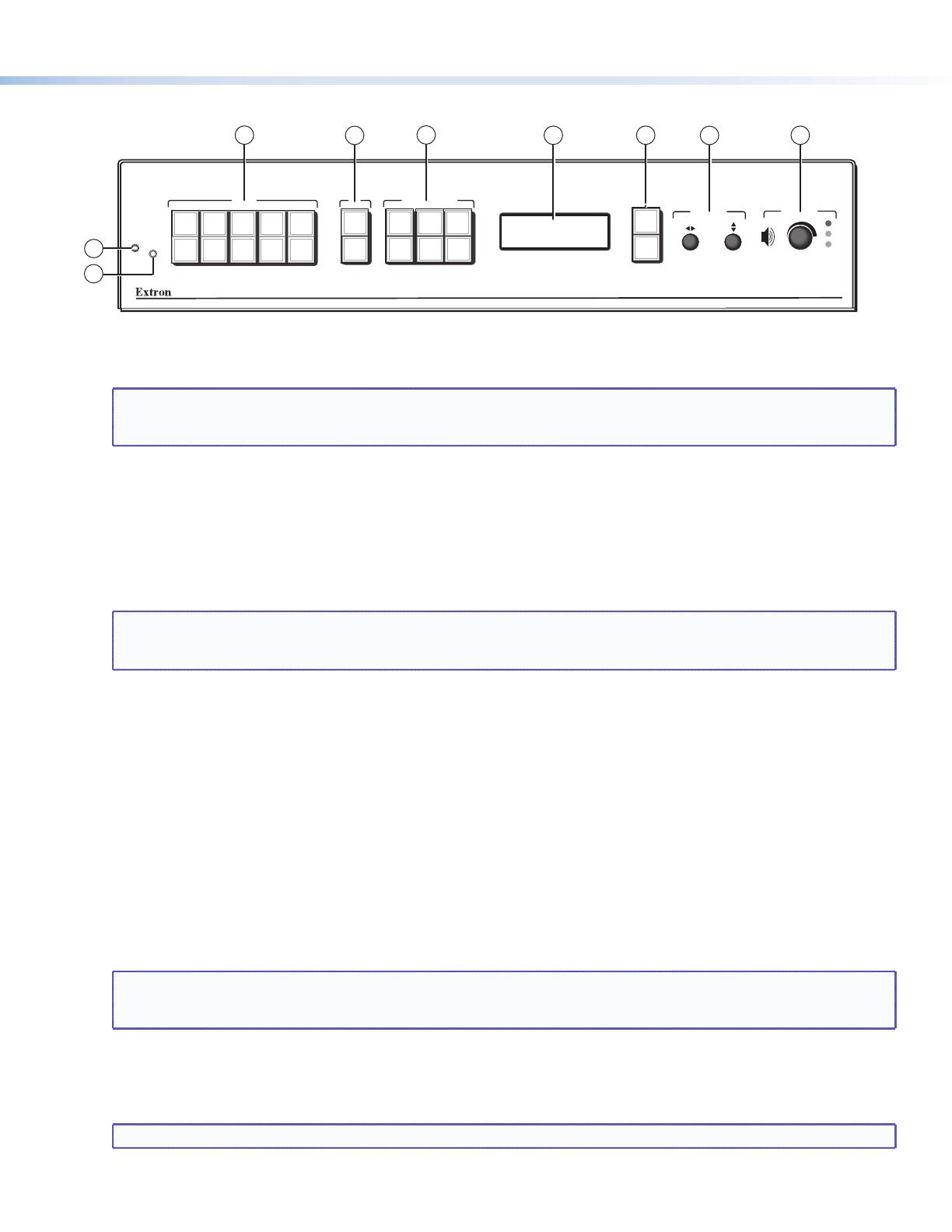
Front Panel Features
MENU
NEXT
DETAIL
ZOOM
/PAN
BRIGHT
/CONT
COLOR
/TINT
SIZE
POSITION
PIP
ON/OFF
PIP
SWAP
CONFIG
IR
MAX
MID
MIN
10
1234
6789
5
ADJUST
VOLUME
PICTURE CONTROLS
PIP
INPUTS
DVS 510
DIGITAL VIDEO SCALER
1
2
3
4
5
6
7
8
9
a Input Buttons — Press one of these buttons to select an input and switch it to the current output. The inputs support
the following signal types: inputs 1 and 2 — composite video; inputs 3 and 4 — S-video; inputs 5, 6, 7, and 9 —
RGB (RGBHV, RGBS, RGBcvS, or RGsB), YUVp/HDTV, and YUVi; and inputs 8 and 10 — DVI.
NOTES: • On the rear panel, inputs 7 and 8 share one of the DVI-I input connectors; inputs 9 and 10 share the
other.
• Pressing and holding the Input button for 3 seconds initiates an Auto-Image on that input.
b PIP (picture-in-picture) control buttons — Display a secondary image from a second source on the screen in front of
the main image, in a previously selected size and position. The default size of the PIP window is one-fourth of the screen
and it is positioned in the lower-right corner of the display.
z PIP On/Off button — Turns PIP mode on and off (toggles between showing and hiding the picture-in-picture on
the display). Lights green when the DVS 510 is in PIP mode.
z PIP Swap button — Toggles the primary (main or background) and secondary (PIP) pictures between the main
image and the PIP window.
NOTE: When the DVS is in PIP mode, one input must be low-resolution (inputs 1 through 4, and 5, 6, 7, and 9
when they are configured as component video YUVi or RGBcvS) and one must be high-resolution (inputs 5,
6, 7, and 9 when configured as RGB or YUVp/HDTV, and inputs 8 and 10).
c Picture control buttons — Adjust window and image size, position, brightness, contrast, color, tint, detail, zoom
(magnify or reduce), and pan. When one of these buttons is pressed, it lights amber.
d LCD screen — Displays messages, menu information, and menu or control button selections.
e Menu navigation buttons — Press Menu to access the DVS 510 menu system and to step through the menus. From
each menu, press Next to step through the submenus.
f Adjust knobs — Rotate these horizontal ([) and vertical ({) knobs to scroll through submenu and picture control
options and make adjustments.
g Volume knob and indicator LEDs — Rotate this knob to adjust the volume on the current input. The three LEDs light
incrementally, bottom to top, to indicate the current volume level:
z Min (green) indicates volume is above 1%. At 0% volume, this LED blinks.
z Mid (green) indicates volume above 49%.
z Max (red) indicates volume above 79%. At 100% volume, this LED blinks.
NOTES: • The volume level is also shown on the LCD screen as a bar graph.
• When an incremental Volume LED lights, the LEDs below it remain lit. For example, when the Max LED
lights, the Mid and Min LEDS are also lit.
h Config port — This RS-232 port on a 2.5 mm TRS connector is an RS-232 only alternative to the rear panel
RS-232/RS-422 port. Default protocol for this port is 9600 baud, 8 data bits,1 stop bit, no parity, and no flow control.
i IR sensor — Receives infrared (IR) signals from the IR 904 remote control.
NOTE: By default, the IR sensor is disabled.