
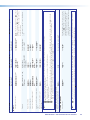
User Guide
DVS 304 Series
Scalers and Scan Converters
Video and RGB Scalers
68-1039-01 Rev. G
05 19

Safety Instructions
Safety Instructions • English
WARNING: This symbol, , when used on the product, is intended to
alert the user of the presence of uninsulated dangerous voltage within the
product’s enclosure that may present a risk of electric shock.
ATTENTION: This symbol, , when used on the product, is intended
to alert the user of important operating and maintenance (servicing)
instructions in the literature provided with the equipment.
For information on safety guidelines, regulatory compliances, EMI/EMF
compatibility, accessibility, and related topics, see the Extron Safety and
Regulatory Compliance Guide, part number 68-290-01, on the Extron
website, www.extron.com.
Sicherheitsanweisungen • Deutsch
WARNUNG: Dieses Symbol auf dem Produkt soll den Benutzer darauf
aufmerksam machen, dass im Inneren des Gehäuses dieses Produktes
gefährliche Spannungen herrschen, die nicht isoliert sind und die einen
elektrischen Schlag verursachen können.
VORSICHT: Dieses Symbol auf dem Produkt soll dem Benutzer in
der im Lieferumfang enthaltenen Dokumentation besonders wichtige
Hinweise zur Bedienung und Wartung (Instandhaltung) geben.
Weitere Informationen über die Sicherheitsrichtlinien, Produkthandhabung,
EMI/EMF-Kompatibilität, Zugänglichkeit und verwandte Themen finden Sie in
den Extron-Richtlinien für Sicherheit und Handhabung (Artikelnummer
68-290-01) auf der Extron-Website, www.extron.com.
Instrucciones de seguridad • Español
ADVERTENCIA: Este símbolo, , cuando se utiliza en el producto,
avisa al usuario de la presencia de voltaje peligroso sin aislar dentro del
producto, lo que puede representar un riesgo de descarga eléctrica.
ATENCIÓN: Este símbolo, , cuando se utiliza en el producto, avisa
al usuario de la presencia de importantes instrucciones de uso y
mantenimiento recogidas en la documentación proporcionada con el
equipo.
Para obtener información sobre directrices de seguridad, cumplimiento
de normativas, compatibilidad electromagnética, accesibilidad y temas
relacionados, consulte la Guía de cumplimiento de normativas y seguridad
de Extron, referencia 68-290-01, en el sitio Web de Extron, www.extron.com.
Instructions de sécurité • Français
AVERTISSEMENT : Ce pictogramme, , lorsqu’il est utilisé sur le
produit, signale à l’utilisateur la présence à l’intérieur du boîtier du
produit d’une tension électrique dangereuse susceptible de provoquer
un choc électrique.
ATTENTION : Ce pictogramme, , lorsqu’il est utilisé sur le produit,
signale à l’utilisateur des instructions d’utilisation ou de maintenance
importantes qui se trouvent dans la documentation fournie avec le
matériel.
Pour en savoir plus sur les règles de sécurité, la conformité à la
réglementation, la compatibilité EMI/EMF, l’accessibilité, et autres sujets
connexes, lisez les informations de sécurité et de conformité Extron, réf.
68-290-01, sur le site Extron, www.extron.com.
Istruzioni di sicurezza • Italiano
AVVERTENZA: Il simbolo, , se usato sul prodotto, serve ad
avvertire l’utente della presenza di tensione non isolata pericolosa
all’interno del contenitore del prodotto che può costituire un rischio di
scosse elettriche.
ATTENTZIONE: Il simbolo, , se usato sul prodotto, serve ad avvertire
l’utente della presenza di importanti istruzioni di funzionamento e
manutenzione nella documentazione fornita con l’apparecchio.
Per informazioni su parametri di sicurezza, conformità alle normative,
compatibilità EMI/EMF, accessibilità e argomenti simili, fare riferimento
alla Guida alla conformità normativa e di sicurezza di Extron, cod. articolo
68-290-01, sul sito web di Extron, www.extron.com.
Instrukcje bezpieczeństwa • Polska
OSTRZEŻENIE: Ten symbol, , gdy używany na produkt, ma na celu
poinformować użytkownika o obecności izolowanego i niebezpiecznego
napięcia wewnątrz obudowy produktu, który może stanowić zagrożenie
porażenia prądem elektrycznym.
UWAGI: Ten symbol, , gdy używany na produkt, jest przeznaczony do
ostrzegania użytkownika ważne operacyjne oraz instrukcje konserwacji
(obsługi) w literaturze, wyposażone w sprzęt.
Informacji na temat wytycznych w sprawie bezpieczeństwa, regulacji
wzajemnej zgodności, zgodność EMI/EMF, dostępności i Tematy pokrewne,
zobacz Extron bezpieczeństwa i regulacyjnego zgodności przewodnik, część
numer 68-290-01, na stronie internetowej Extron, www.extron.com.
安全说明 • 简体中文
警告: 产品上的这个标志意在警告用户该产品机壳内有暴露的危险 电压,
有触电危险。
注意: 产品上的这个标志意在提示用户设备随附的用户手册中有
重要的操作和维护(维修)说明。
关于我们产品的安全指南、遵循的规范、EMI/EMF 的兼容性、无障碍
使用的特性等相关内容,敬请访问 Extron 网站 , www.extron.com,参见
Extron 安全规范指南,产品编号 68-290-01。

안전 지침 • 한국어
경고: 이 기호 가 제품에 사용될 경우, 제품의 인클로저 내에 있는
접지되지 않은 위험한 전류로 인해 사용자가 감전될 위험이 있음을
경고합니다.
주의: 이 기호 가 제품에 사용될 경우, 장비와 함께 제공된 책자에 나와
있는 주요 운영 및 유지보수(정비) 지침을 경고합니다.
안전 가이드라인, 규제 준수, EMI/EMF 호환성, 접근성, 그리고 관련 항목에
대한 자세한 내용은 Extron 웹 사이트(www.extron.com)의 Extron
안전 및 규제 준수 안내서, 68-290-01 조항을 참조하십시오.
安全記事 • 繁體中文
警告: 若產品上使用此符號,是為了提醒使用者,產品機殼內存在著
可能會導致觸電之風險的未絕緣危險電壓。
注意 若產品上使用此符號,是為了提醒使用者,設備隨附的用戶手冊中有
重要的操作和維護(維修)説明。
有關安全性指導方針、法規遵守、EMI/EMF 相容性、存取範圍和相關主題的詳細資
訊,請瀏覽 Extron 網站:www.extron.com,然後參閱《Extron 安全性
與法規遵守手冊》,準則編號 68-290-01。
安全上のご注意 • 日本語
警告: この記号 が製品上に表示されている場合は、筐体内に絶縁されて
いない高電圧が流れ、感電の危険があることを示しています。
注意:この記号 が製品上に表示されている場合は、本機の取扱説明書に
記載されている重要な操作と保守(整備)の指示についてユーザーの注意
を喚起するものです。
安全上のご注意、法規厳守、EMI/EMF適合性、その他の関連項目に
つ い て は 、エ ク スト ロ ン の ウェ ブ サ イト www.extron.com よ り 『 Extron
Safety and Regulatory Compliance Guide』 ( P/N 68-290-01) をご覧ください。
Copyright
© 2011-2019 Extron Electronics. All rights reserved. www.extron.com
Trademarks
All trademarks mentioned in this guide are the properties of their respective owners.
The following registered trademarks (
®
), registered service marks (
SM
), and trademarks (
TM
) are the property of RGBSystems, Inc. or
ExtronElectronics (see the current list of trademarks on the Terms of Use page at www.extron.com):
Registered Trademarks
(
®
)
Extron, Cable Cubby, ControlScript, CrossPoint, DTP, eBUS, EDID Manager, EDID Minder, Flat Field, FlexOS, Glitch Free. Global
Configurator, GlobalScripter, GlobalViewer, Hideaway, HyperLane, IPIntercom, IPLink, KeyMinder, LinkLicense, LockIt, MediaLink,
MediaPort, NetPA, PlenumVault, PoleVault, PowerCage, PURE3, Quantum, Show Me, SoundField, SpeedMount, SpeedSwitch,
StudioStation, SystemINTEGRATOR, TeamWork, TouchLink, V-Lock, VideoLounge, VN-Matrix, VoiceLift, WallVault, WindoWall, XTP,
XTPSystems, and ZipClip
Registered Service Mark
(SM)
: S3 Service Support Solutions
Trademarks
(
™
)
AAP, AFL (Accu-RateFrameLock), ADSP(Advanced Digital Sync Processing), Auto-Image, AVEdge, CableCover, CDRS(ClassD
Ripple Suppression), Codec Connect, DDSP(Digital Display Sync Processing), DMI (DynamicMotionInterpolation), DriverConfigurator,
DSPConfigurator, DSVP(Digital Sync Validation Processing), eLink, EQIP, Everlast, FastBite, FOX, FOXBOX, IP Intercom HelpDesk,
MAAP, MicroDigital, Opti-Torque, PendantConnect, ProDSP, QS-FPC(QuickSwitch Front Panel Controller), RoomAgent, Scope-Trigger,
ShareLink, SIS, SimpleInstructionSet, Skew-Free, SpeedNav, Triple-Action Switching, True4K, Vector™ 4K , WebShare, XTRA, and
ZipCaddy

FCC Class A Notice
This equipment has been tested and found to comply with the limits for a Class A digital
device, pursuant to part15 of the FCC rules. The ClassA limits provide reasonable
protection against harmful interference when the equipment is operated in a commercial
environment. This equipment generates, uses, and can radiate radio frequency energy and,
if not installed and used in accordance with the instruction manual, may cause harmful
interference to radio communications. Operation of this equipment in a residential area is
likely to cause interference. This interference must be corrected at the expense of the user.
NOTES:
• This unit was tested with shielded I/O cables on the peripheral devices. Shielded
cables must be used to ensure compliance with FCC emissions limits.
• For more information on safety guidelines, regulatory compliances, EMI/EMF
compatibility, accessibility, and related topics, see the Extron Safety and
Regulatory Compliance Guide on the Extron website.
Battery Notice
This product contains a battery. Do not open the unit to replace the battery. If the
battery needs replacing, return the entire unit to Extron (for the correct address, see the
Extron Warranty section on the last page of this guide).
CAUTION: Risk of explosion. Do not replace the battery with an incorrect type. Dispose
of used batteries according to the instructions.
ATTENTION : Risque d’explosion. Ne pas remplacer la pile par le mauvais type de pile.
Débarrassez-vous des piles usagées selon le mode d’emploi.

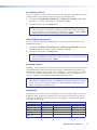
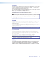
Conventions Used in this Guide
Notifications
The following notifications are used in this guide:
WARNING: Potential risk of severe injury or death.
AVERTISSEMENT : Risque potentiel de blessure grave ou de mort.
CAUTION: Risk of minor personal injury.
ATTENTION : Risque de blessuremineure.
ATTENTION:
• Risk of property damage.
• Risque de dommages matériels.
NOTE: A note draws attention to important information.
Software Commands
Commands are written in the fonts shown here:
^AR Merge Scene,,0p1 scene 1,1 ^B 51 ^W^C.0
[01] R 0004 00300 00400 00800 00600 [02] 35 [17] [03]
E X! *X1&* X2)* X2#* X2! CE}
NOTE: For commands and examples of computer or device responses used in this
guide, the character “0” (Extron Mono font Regular) is used for the number zero
and “O” is the capital letter “o.”
Computer responses and directory paths that do not have variables are written in the font
shown here:
Reply from 208.132.180.48: bytes=32 times=2ms TTL=32
C:\Program Files\Extron
Variables are written in slanted form as shown here:
ping xxx.xxx.xxx.xxx —t
SOH R Data STX Command ETB ETX
Selectable items, such as menu names, menu options, buttons, tabs, and field names are
written in the font shown here:
From the File menu, select New.
Click the OK button.
Specifications Availability
Product specifications are available on the Extron website, www.extron.com.
Extron Glossary of Terms
A glossary of terms is available at http://www.extron.com/technology/glossary.aspx.


Contents
Introduction ................................................1
DVS304 Series Description ................................. 1
DVS304 Models ............................................. 2
DVS304 DVI Models ....................................... 2
Features .............................................................. 2
Controlling the DVS304 Devices ......................... 3
Options and Accessories ..................................... 4
Cabling ....................................................... 5
Rear Panel Cabling .............................................. 5
Operation....................................................9
Front Panel Overview ........................................... 9
Menus, Configuration, and Adjustments ............ 10
Menu Navigation Using
Front Panel Controls ..................................... 10
Menu Overview .............................................. 10
Start Auto Image ........................................... 12
Input Configuration ........................................ 13
Picture Control ............................................... 14
Output Configuration ..................................... 14
Audio Configuration (Audio Models Only) ....... 16
Memory Preset .............................................. 16
IP Configuration ............................................ 18
Advanced Configuration ................................ 18
Exit Menu ...................................................... 23
Resetting an Input ......................................... 23
Resetting the Unit .......................................... 24
System Reset ................................................ 25
Front Panel Lockout (Executive Modes) ............. 25
Setting up the DVS to Work with
a Matrix Switcher .............................................. 26
Using the DVS and Matrix Switcher After the
DVS is Synchronized to
the Matrix Switcher ....................................... 28
Removing the Sync to Matrix Script ............... 28
Minimizing Synchronization Problems
Without Using the Sync to Matrix Feature ..... 29
SIS Communication and Control ................30
Host to Scaler Communications ........................ 30
Scaler-initiated Messages .............................. 31
Copyright Information .................................... 31
Password Information .................................... 31
Error Responses ............................................ 31
Error Response References ........................... 32
Command and Responses ................................ 32
Using the Command and Response Tables ... 32
Symbol Definitions ......................................... 33
Command and Response Table for
SIS Command .................................................. 37
Command and Response Table for
IP Control Port SIS Commands ........................ 46
Signal Processing
Products Control Program ......................... 54
Installing the Software ........................................ 54
Installation from the Website .......................... 54
Starting SPPCP ............................................. 55
Using SPPCP .................................................... 55
Orientation ..................................................... 55
SPPCP Menus ............................................... 56
Control Tab .................................................... 62
I/O Configuration Tab ..................................... 63
Advanced Settings Tab .................................. 64
Status Bar ..................................................... 64
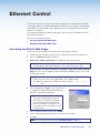
Ethernet Control........................................65
Accessing the Default Web Pages ..................... 65
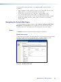
Navigating the Default Web Pages ..................... 66
Status ........................................................... 66
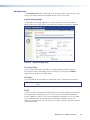
Configuration ................................................. 67
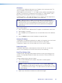
File Management ........................................... 72
Control .......................................................... 73
DVS 304 Series • Contents vii

Menu System ............................................75
Default Cycle Menu........................................ 75
Main Menu .................................................... 75
Start Auto Image Menu .................................. 76
Input Configuration Menu .............................. 76
Picture Control ............................................... 76
Output Configuration Menu............................ 77
Audio Configuration Menu ............................. 77
Memory Preset Menu .................................... 77
IP Configuration Menu ................................... 78
Advanced Configuration Menu ....................... 78
Exit Menu ...................................................... 78
Executive Mode Menu ................................... 79
Mounting ..................................................80
Tabletop Placement ........................................... 80
Rack Mounting .................................................. 80
UL Guidelines for Rack Mounted Devices ..... 80
Rack Mounting the DVS304 ......................... 81
Furniture Mounting ............................................ 81
DVS 304 Series • Contents viii

Introduction
This manual contains information about the Extron DVS304 Series of scalers with
instructions for experienced installers on how to install, configure, and operate the
equipment.
This section gives an overview of the DVS304 Series, incuding:
• DVS304 Series Description
• Features
• Controlling the DVS304 Devices
• Options and Accessories
In this manual the terms “DVS”, “digital video scaler”, and “scaler” are used
interchangeably and refer to any DVS304 Series model.
DVS304 Series Description
The DVS304 Series of digital video scalers is comprised of DVS304 and DVS304 DVI
models:
• DVS304, DVS304 D, DVS304 A, and DVS304 AD
• DVS304 DVI, DVS304 DVI D, DVS304 DVI A, and DVS304 DVI AD
They are available as half rack, non-audio models or full rack size models with balanced/
unbalanced audio.
• Half rack: DVS304, DVS304 D, DVS304 DVI, DVS304 DVI D
• Full rack: DVS304 A, DVS304 AD, DVS304 DVI A, and DVS304 AD:
All models are 4-input, 1-output, high performance RGB and video scalers, providing
scaling solutions for boardrooms, conference rooms, and home theaters, as well as rental
and staging applications. The DVS304 series scales from composite video, S-video,
component (Y, R-Y, B-Y) video, and RGB video to computer-video (RGBHV/RGBS/RGsB)
or HD component.
The four inputs of all DVS models accommodate composite video, S-video, component
video, and RGB. The fourth input is fully configurable to accept any available analog
video format from composite video to RGBHV. Additionally, with the exclusive Auto Input
Format Detection mode, the DVS304 devices automatically detect and then process the
incoming signal format to this input.
The DVS304 Series audio models offer four input audio switching for stereo unbalanced
or balanced sources, with gain and attenuation controls available for each input. All audio
connections are on captive screw connectors for ease of integration, and output volume
control eliminates the need for a separate audio preamplifier in many A/V systems.
DVS 304 Series • Introduction 1

DVS304 Models
On these models, two identical, scaled outputs are available on 15-pin HD and BNC
connectors. A total of 69 output scan rates are available from VGA (640x480) to UXGA
(1600x1200) resolution, as well as HDTV at 720p, 1080i, and 1080p/60 Hz.
NOTE: See the Resolutions and Refresh Rates on page15, for a
comprehensive list.
DVS304 DVI Models
The DVS304 DVI offers simultaneous digital and analog scaled outputs through the
DVI-I port. Simultaneous analog scaled output is also available on BNC connectors. A
total of 70 output scan rates are available from VGA (640x480) to WUXGA (1920x1200)
resolution, as well as HDTV at 720p, 1080i, and 1080p/60 Hz.
In addition the DVS304 DVI features EDID Minder, which enables automatic and
continuous management of the EDID information between the computer-video input
source and the display, ensuring that the source powers up properly and reliably outputs
content to the display.
Features
• Four inputs —
• Input 1 – One BNC connector accepts composite video.
• Input 2 – Three BNC connectors accept composite video, S-video, or component
video.
• Input 3 – A 4-pin mini-DIN connector accepts an S-video signal.
• Input 4 – A 15-pin HD connector accepts an RGB, component video, S-video, or
composite video signal.
• SDI video input (optional) – One BNC connector accepts SDI video. During setup,
the SDI input is assigned to input 1, 2, 3, or 4 (the default is none).
• RGB and video scaling — Provides a high performance scaling engine with the
capacity to scale standard definition video, high definition video, and computer-video
signals up or down in resolution.
• Picture control — Allows size, position, brightness, contrast, color, tint, detail, zoom
and pan adjustments for each input.
• Picture-In-Picture — Allows for a low resolution (YUVi, S-video, composite video,
and SDI) input and a high resolution (VGA and YUVp/HDTV) input to be displayed
simultaneously.
• Memory and input presets — Memory presets save sizing, positioning, and picture
control settings.
Input presets (on input 4 only) save input configuration, picture control, and OSD
(on-screen display) text.
• Auto-Image — Auto-Image automatically sizes, centers, and optimizes the image to
that of the scaled output rate, filling the window with the image.
• IP Link — IP Link-enabled products offer an integrated web server with high
performance architecture, global compatibility with industry standard Ethernet
communication protocols, multi-user support, and a web-based asset management
application specifically designed to work with products that include IP Link
technology.
DVS 304 Series • Introduction 2

• Buffered video outputs —
• DVS304 models – Five rear-panel BNC connectors and one VGA-type 15-pin HD
connector provide connections for RGB or Y, R-Y, B-Y output. Both outputs are
active at all times for simultaneous output.
• DVS304 DVI models – Five rear-panel BNC connectors and one DVI-I connector
provide analog and digital output (DVI-I) and analog output (BNC). All outputs are
active at all times for simultaneous output of RGB or Y, R-Y, B-Y. DVI-D output is
disabled for RGB pass-though.
• Device control — The scaler has four methods of control: by its front panel, via a
computer or other RS-232/Ethernet control device, using the optional IR 902 remote
control, or via the Signal Processing Products Control Program (SPPCP).
• Scaled outputs — The DVS304 models offer 69 output rates and the DVS304 DVI
models offer 70 output rates.
• RS-232 configuration — All DVS304 series units can be configured by using the
Extron control software for Windows
®
or by using a control system.
• Front panel security lockout (executive mode) — To prevent accidental changes
to the settings on the unit, the scaler provides front panel lockout of all controls
except input switching. A second executive mode completely disables all front panel
controls.
• 3:2 pull down detection for NTSC and 2:2 film detection for PAL video
sources — These patented, advanced film mode processing features help maximize
image detail and sharpness for video sources that originated from film. When film is
converted to NTSC video, the film frame rate has to be matched to the video frame
rate in a process called 3:2 pull down. “Jaggies” and other image artifacts can result if
conventional de-interlacing techniques are used on film-source video. The advanced
film mode processing on the digital video scaler recognizes signals that originated
from film. The scaler then applies video processing algorithms that optimize the
conversion of video that was made with the 3:2 pull down process. This results in
richly detailed images with sharply defined lines. A similar process is used for PAL
film-source video.
• Versatile mounting options — The non-audio models are 1U high, half rack wide
rack mountable devices. Alternatively, they can be placed on a table or other furniture.
Rubber feet are included.
The audio models are 1U high and full rack size and can be rack or desk mounted
using included rack or through-desk mounting brackets.
Controlling the DVS304 Devices
All DVS304 series devices can be controlled using one or more of the following methods:
• The front panel controls.
• A computer, a touch screen panel, or any other device that can send and receive
the serial communications through the RS-232 or Ethernet port. The Extron Simple
Instruction Set (SIS) is a set of simple keystroke commands that can be used with any
such devices.
• Extron Signal Processing Products Control Program (SPPCP) software for Windows
provides a graphical interface for controlling the scaler from a computer.
• The optional IR 902 remote control, replicating most of the front panel controls.
• Ethernet control via IP Link, enabling the scaler to be controlled and actively
monitored over a LAN, WAN, or the Internet.
DVS 304 Series • Introduction 3

Options and Accessories
The DVS304 series optional equipment includes:
• IR 902 remote control — The Extron IR 902 is an infrared remote control that
replicates most of the front panel controls of the digital video scaler (except the Menu
and Next buttons).
• SDI input card — Serial digital interface (SDI) input can be added to a DVS304
model by the installation of an SDI input card.
DVS 304 Series • Introduction 4

Cabling
This section describes how to connect cables to a DVS304 series device.
Rear Panel Cabling
The illustration below shows the all possible rear panel features of the audio and
non-audio models.
K
INPUTS OUTPUT
VID
1
4
2
3
Y
/VID
R-Y
H/
HV
R
/R-Y
V
G
/Y
RS-232
LAN
RESET
B
/B-Y
ACTLINK
RGB/R-Y, Y, B-Y
YC
SDI
B-Y
/C
RGB/R-Y,Y
N
P
U
T
,B-Y/YC/VID
I
T
P
U
T
O
U
50/60 Hz
2
1
3
4
LR
LR
LR
LR
LR
100-240V .3
N
P
U
T
A
U
T
P
U
I
AUDIO
O
T
VID
50/60 Hz
1
2
3
4
Y
/VID
R-Y
H/
HV
R
/R-Y
V
G
/Y
B
/B-Y
RS-232
LAN
RESET
ACTLINK
RGB/R-Y,Y,B-Y
YC
SDI
B-Y
/C
RGB/R-Y,Y,B-Y/YC/VID
100-240V .3A
I
N
P
U
T
O
U
T
P
U
T
INPUTS OUTPUT
RS-232
LAN
RESET
AC
TLINK
50/60 Hz
100-240V .3
2
1
3
4
LR
LR
LR
LR
LR
A
AUDIO
VID
1
2
4
3
Y
/VID
R-
H/
Y
HV
R
/R-Y
V
G
/Y
B
/B-Y
DVI-I
YC
SDI
B-Y
/C
RGB/R-
Y,Y,B-Y/YC/VID
I
P
U
T
N
O
T
P
U
T
U
4
Y
/VID
R
/R-Y
G
/Y
B
/B-Y
RS-232
LAN
RESET
SDI
B-Y
/C
RGB/R-
Y,Y,B-Y/YC/VID
100-240V .3A
I
N
P
U
T
O
U
T
P
U
T
VID
50/60 Hz
1
2
3
R-Y
H/
HV
V
ACTLINK
DVI-I
YC
DVS 304 D
DVS 304 DVI D
DVS 304 DVI AD
DVS 304 AD
(Optional)
(Optional)
(Optional)
(Optional)
A
BC
F
H
I
E
GJKL
AB
D
CF
G
D
EH
IJ
K
L
ADF
G
EH L
IJ JK
E
ADFG
H
L
I
A
Power input
G
Video input 3: S-video
B
Audio input
H
Video input 4: RGB/R-Y, Y, B-Y/YC/VID
C
Audio output
I
RGB (RGBHV, RGBS, RGsB) or
HD component (R-Y, Y, B-Y)
video BNC outputs
D
Video input 1: Composite video
J
Reset button and LED
E
Optional SDI input connector
K
LAN connector
F
Video input 2: Composite/S-video/
Component
L
Remote (RS-232/contact closure) port
Figure 1. DVS304 Devices Rear Panel Features
A
Power input — Connect the standard IEC power cord from a 100 to 240 VAC,
50 Hz or 60 Hz power source into this connector. The front panel control and input
selection buttons light in sequence during power-up.
1
DVS 304 Series • Cabling 5

B
Audio input — Plug in up to four, 3.5 mm, female, five-pole, captive screw
connectors for balanced/unbalanced variable audio input (see figure1 on
the previous page).
C
Audio output — Plug in one, 3.5 mm, female, five-pole captive screw
connector for balanced/unbalanced variable audio output. Wire the
connector as shown below.
L
MONO AUDIO
R
L
MONO AUDIO
R
Unbalanced Output
Balanced Output
Do not tin the wires!
Mono output 1-
Sleeve(s)
Mono output 1+
Mono output 2+
Mono output 2-
Sleeve(s)
Mono output 1
Mono output 2
NO GROUND.
NO GROUND.
Figure 2. Audio connector wiring
D
Video input 1: Composite video — Connect a composite video signal to this
female, BNC connector.
E
Optional SDI (serial digital interface) input connector — Connect an SDI signal
to this female BNC connector. During setup, the SDI input can be assigned to one of
the other unused inputs.
F
Video input 2: Composite/S-video/Component — Connect composite video,
S-video, and component video signals. Connect cables for the appropriate signal
type, as shown below.
Composite Video
2
Y
/VID
B-Y
/C
R-Y
2
R-Y
Y
/VID
B-Y
/C
C
omponent Video (Y, R-Y, B-Y)
2
B-Y
/C
S-video (YC)
Y
/VID
R-Y
Figure 3. Input 2 Connector Cabling
G
Video input 3: S-video — Connect an S-video signal to this 4-pin,
mini-DIN female connector.
H
Video input 4: RGB/R-Y, Y, B-Y/YC/VID — Connect RGBHV, RGBS,
RGsB, RGBcvS, YUVi, YUVp/HDTV, S-video and composite video
through this 15-pin HD connector (see pin configurations below).
NOTE: DVS304 DVI models feature EDID emulation on this 15-pin HD connector.
Signal Input 4 Configuration
Pin 1 Pin 2 Pin 3 Pin 13 Pin 14
RGBHV R G B H V
RGBS R G B S
RGBcvS R G B S
RGsB R Gs B
YUV R-Y Y B-Y
S-video Y C
Video Vid
Figure 4. Input 4 Pinout Table
2
3
4
SDI
1
VID
RGB/R-Y,Y,B-Y/YC/VID
4
3
YC
1
2
13
3
14
DVS 304 Series • Cabling 6

I
RGB (RGBHV, RGBS, RGsB) or HD component (R-Y, Y, B-Y) video BNC
outputs — Connect cables from a display device to these BNCs for a scaled or
pass-through RGB or a scaled component video output (see figure1 on page5).
The output can be scaled to 69 different output rates (see the Resolution table on
page15).
RGBHV
H/
HV
R
/R-Y
V
G
/Y
B
/B-Y
R
/R-Y
G
/Y
B
/B-Y
RGsB
H/
HV
V
R
/R-Y
V
G
/Y
RGBS\RGBcvS
H/
HV
B
/B-Y
B
/B-Y
Component Video (Y, R-Y,
B-Y)
R
/R-Y
G
/Y
H/
HV
V
Figure 5. RGB Cabling
(DVS304 models only) RGB or HD component (R-Y, Y, B-Y) 15-pin HD video
output — Connect an RGB video display or HD component video display to this HD
15-pin connector.
NOTE: Outputs are buffered and can be connected simultaneously to two
different displays. The sync and video formats will be the same for both outputs.
(DVS304 DVI models only) DVI (digital and analog) output —
Connect a suitable display device to this DVI-I connector for scaled
RBG or component video digital and analog outputs.
J
Reset button and LED — Using an Extron Tweeker, pointed stylus, or ballpoint pen,
press this recessed button for manual resets. The unit has four modes of reset (see
Resetting the Unit on page 24 for additional information). The green LED flashes to
show the reset mode indicators and that power is on.
K
LAN connector — Plug an RJ-45 jack into this socket to connect the unit to a
computer network. Use a patch cable to connect to a switch, hub, or router (see
figure 6, below, for wiring information).
LAN Activity LED — A blinking yellow LED indicates LAN activity.
Link LED — The green LED lights to indicate a good LAN connection.
12345678
RJ-45
Connector
Insert Twisted
Pair Wires
Pins:
Pin
1
2
3
4
5
6
7
8
Wire color
White-green
Green
White-orange
Blue
White-blue
Orange
White-brown
Brown
Wire color
T568A T568B
White-orange
Orange
White-green
Blue
White-blue
Green
White-brown
Brown
NOTE: If you are using Enhanced Skew-Free
AV cable, use the TIA/EIA T568A standard only.
Figure 6. Wiring the RJ-45 Connector
5
6
DVI-I
DVS 304 Series • Cabling 7

L
Remote (RS-232/contact closure) port — This 9-pin connector
provides for two-way RS-232 communication (see figure1 on page5).
See SIS Communication and Control starting on page30 for
information on how to install and use the control software and
SIS commands. The default protocol is 9600 baud, 1 stop bit,
no parity, and no flow control. The rear panel RS-232 9-pin D
female connector has the pin assignments according to the side image:
Pin RS-232 Function Description
1 Input 1 Contact closure
2 Tx Transmit data
3 Rx Receive data
4 Input 2 Contact closure
5 Ground Signal ground
6 Input 3 Contact closure
7 Input 4 Contact closure
8 - No connection
9 - Reserved
Figure 7. RS-232 Pin-out Table
The Remote connector also provides a way to select an input using a remote contact
closure device. Contact closure control uses pins on the RS-232 connector that are
not used by the RS-232 interface (see figure7).
To select a different input number using a contact closure device, short the pin for the
desired input number to logic ground (pin 5).
NOTE: If contact closure is not in use, pins 1, 4, 6, and 7 should have no
connection.
RS-232
5
9
1
6
7
DVS 304 Series • Cabling 8

Operation
This section of the manual discusses the operation of a DVS304 device, and is divided
into four sections:
• Front Panel Overview
• Menus, Configuration, and Adjustments
• Front Panel Lockout (Executive Modes)
• Setting up the DVS to Work with a Matrix Switcher
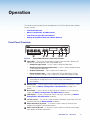
Front Panel Overview
1
DVS 304
DIGITAL VIDEO SCALER
ADJUST
IR
2 3 4 MENU NEXT
B
C
D E
F
A
G
Figure 8. Typical DVS304 Device Front Panel Features
A
Input LEDs — The LED of the selected input lights when pressed. A blinking LED
indicates an audio breakaway input (audio models only).
• Composite input button — Input 1 selects composite video input.
• Composite/YC/component input button — Input 2 selects composite video,
YC,or component video input.
• S-video input button — Input 3 selects the S-video input.
• Universal input button — Input 4 selects the RGB scaled (RGBHV, RGBS,
RGsB), RGB pass-through, YUVi, YUVp/HDTV, S-video and composite video.
NOTE: RGB pass-through signals (at native rate without additional processing)
are available on analog outputs only. The DVI output is disabled for
pass-through.
B
Menu button — Use this button to enter and move through the main menu system
for the scaler (see Menus, Configuration, and Adjustments on page10 for
details).
C
Next button — Use this button to step through the submenus in the scaler menu
system (see Menus, Configuration, and Adjustments for details).
D
LCD display — Displays configuration menus and status information (see Menus,
Configuration, and Adjustments for details).
E
Infrared sensor — This sensor is used to receive infrared (IR) signals from the IR 902
remote control (see the Extron website for details).
F
Adjust horizontal ([) knob — In the menu system, rotate this knob to scroll
through menu options and make adjustments.
G
Adjust vertical ({) knob — In the menu system, rotate this knob to scroll through
menu options and make adjustments.
8
DVS 304 Series • Operation 9

Menus, Configuration, and Adjustments
Scaler configuration and adjustments can be performed by using the embedded web
pages and the Windows-based control program (see SIS Communication and Control
starting on page30 for details) or by using the front panel controls and the menus
displayed on the LCD screen of the DVS unit. These menus are used primarily when the
scaler is first set up.
Menu Navigation Using Front Panel Controls
Menu button — Press the Menu button to activate menus and scroll through the eight
main menus.
Next button — Press the Next button to move between the submenus of a selected
main menu. Pressing the Next button during input configuration causes the current
number and format type of the input to be displayed on the LCD.
Adjust ([,{) knobs — In configuration mode, rotate the Adjust horizontal ([) knob
and Adjust vertical ({) knob to scroll through submenu options and to make adjustment
selections. Refer to the flowcharts in this chapter and to specific sections for explanations
on knob adjustments.
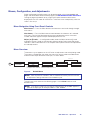
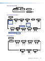
Menu Overview
The Default Cycle appears on the LCD when no adjustments are actively being made.
The screens cycle between the screen that shows the active number and video format
and the current output resolution of the input, as shown below:
DVS 304
xxx xx
2 sec.
INPUT 1
COMPOSITE
60-xxxx-xx
FW ver. 1.xx
2 sec.
2 sec.
OUTPUT
1024 x 768@60
Default Cycle
2 sec.
Power
on
EXTRON
ELECTRONICS
2 sec.
Displays specific model name
(for example DVS 304 DVI AD)
Displays specific model part
number (for example 60-1027-04)
Figure 9. Default Menus
NOTE: From any menu or submenu, after 20 seconds of inactivity the DVS will save
all adjustment settings and time-out to the default cycle.
The main menus are shown on the following pages. Use the Menu button to scroll
between them.
NOTE: If no signal is present on the currently selected input, NO SIGNAL appears in
place of the input type, for example, INPUT 4 NO SIGNAL.
9
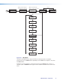
DVS 304 Series • Operation 10

START AUTO
IMAGE ON IN1
MENU
MENU
INPUT
CONFIG
MENU
PICTURE
CONTROL
MENU
OUTPUT
CONFIG
MENU
AUDIO
CONFIG
MENU
NEXT
MENU
MEMORY
PRESETS
INPUT 1
COMPOSITE
2 sec.
60-xxxx-0x
FW version 1.00
2 sec.
2 sec.
OUTPUT
1024 x 768@60
Default Cycle
2 sec.
IP
CONFIG
MENU
MENU
ADVANCED
CONFIG
MENU
TO EXIT MENU
PRESS NEXT
(Audio models only)
Power
on
EXTRON
ELECTRONICS
2 sec.
DVS 304
xxx xx
Displays specific model name
(for example DVS 304 DVI AD)
Displays specific model part
number (for example 60-1027-04)
Figure 10. Main Menu
To return to the default cycle, allow the DVS304 to time-out (after 20 seconds).
Alternatively, press the Menu button repeatedly until the Exit menu appears, then press
the Next button.
Submenus are accessed from a main menu by pressing the Next button. When in a
submenu, press the Menu button to go out of the submenu and back to the active main
menu.
10
DVS 304 Series • Operation 11

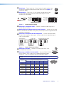
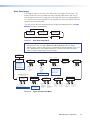
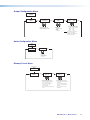
Start Auto Image
Auto image an input to “auto size” and “auto center” the image to fill the screen. The
processor measures the sync frequencies from incoming video sources and uses an
internal table to set the active image area, total image area, and the sampling frequency.
If an unknown input is connected to the unit, the processor measures and estimates the
resolution of the incoming video.
The DVS304 can be set to automatically auto-image newly detected inputs (see Auto
Memory on page21 for full details).
Default Cycle
INPUT 1
COMPOSITE
2 sec.
2 sec.
OUTPUT
1024 x 768@60
MENU
START AUTO
IMAGE ON IN1
PRESS NEXT
TO START
NEXT
NEXT
Figure 11. Start Auto Image Menu
NOTE: An input with a vertical refresh rate less than 40 Hz will have to be manually
centered and sized, using H/V Start and H/V Active under the Input
Config menu. When a rate with a low vertical refresh rate (for example 720p, 29.9
Hz) is applied and an auto image command is issued, the DVS refers to default
values instead of performing a true auto image.
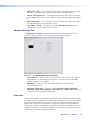
START AUTO
IMAGE ON IN1
INPUT
CONFIG
MENU
NEXT
INPUT 2
YUVi
INPUT 4
RGB SCALED
NEXT
ASPECT RATIO
4x3
TTLPIX PHASE
XXXX 08
NEXT
NEXT
NEXT
H START V
50 33
H ACTIVE V
XXX XXX
NEXT
FILM MODE
<OFF> ON
SDI INPUT
<
*
> 1 2 3 4
NEXT
NEXT
Displays only when applicable
Displays only when applicable Displays only when applicable
SDI DE-INTER
FIELD STNDRD
NEXT
Displays only when applicable
NEXT
DVS 304 DVI models only
Displays only on Input 4
NEXT
Select video format
• Composite
• S-video
• YUVi
• YUVp/HDTV
• YUV Auto
Assign SDI to Input #
• 1, 2, 3, 4, * (none)
Select video format
• Composite
• S-video
• RGBcvS
• YUVi
• YUVp/HDTV
• RGB scaled
• RGB pass*
• Auto detect
Aspect ratio options
• 4 x 3
• 16 x 9
For YUVp or RGB input only
Total pixels
Specify the width
in pixels of the
total image area
sampled.
Pixel phase
Adjust the pixel
sampling point for
a selected input.
Horizontal start
Select for the
left edge of the
active video.
Vertical start
Select for the
top edge of the
active video.
Horizontal active
pixels
Specify the width
in pixels of the
active image area
sampled.
Vertical active
lines
Specify the
height in lines of
the active image
area sampled.
Film mode
Tu rn On or Off for low
resolution devices.
SDI De-interlacing options:
• Field Standard
• Field Flip
VGA EDID
1024x768@60
EDID Emulation
Specify the resolution
and refresh rate.
NOTE:
Input 1 can only
accept composite video.
Input 3 can only accept
S-video. Only Inputs 2 and
4 can be configured for
different video types,
although an SDI input can
be assigned to any input.
NOTE: The SDI input signal
can be assigned to any
input. Once assigned to a
specic input, only an SDI
signal can be accepted on
that input. SDI can be
disabled by selecting the *.
NOTE: See table in the “Resolutions
and Refresh Rates” section, for EDID values.
NOTE: Not for use with
YUVp or RGB inputs.
NOTE:
* RGB pass through is only
available on analog outputs.
Figure 12. Figure Configuration Menu
11
12
DVS 304 Series • Operation 12
Page is loading ...
Page is loading ...
Page is loading ...
Page is loading ...
Page is loading ...
Page is loading ...
Page is loading ...
Page is loading ...
Page is loading ...
Page is loading ...
Page is loading ...
Page is loading ...
Page is loading ...
Page is loading ...
Page is loading ...
Page is loading ...
Page is loading ...
Page is loading ...
Page is loading ...
Page is loading ...
Page is loading ...
Page is loading ...
Page is loading ...
Page is loading ...
Page is loading ...
Page is loading ...
Page is loading ...
Page is loading ...
Page is loading ...
Page is loading ...
Page is loading ...
Page is loading ...
Page is loading ...
Page is loading ...
Page is loading ...
Page is loading ...
Page is loading ...
Page is loading ...
Page is loading ...
Page is loading ...
Page is loading ...
Page is loading ...
Page is loading ...
Page is loading ...
Page is loading ...
Page is loading ...
Page is loading ...
Page is loading ...
Page is loading ...
Page is loading ...
Page is loading ...
Page is loading ...
Page is loading ...
Page is loading ...
Page is loading ...
Page is loading ...
Page is loading ...
Page is loading ...
Page is loading ...
Page is loading ...
Page is loading ...
Page is loading ...
Page is loading ...
Page is loading ...
Page is loading ...
Page is loading ...
Page is loading ...
Page is loading ...
Page is loading ...
Page is loading ...
-
 1
1
-
 2
2
-
 3
3
-
 4
4
-
 5
5
-
 6
6
-
 7
7
-
 8
8
-
 9
9
-
 10
10
-
 11
11
-
 12
12
-
 13
13
-
 14
14
-
 15
15
-
 16
16
-
 17
17
-
 18
18
-
 19
19
-
 20
20
-
 21
21
-
 22
22
-
 23
23
-
 24
24
-
 25
25
-
 26
26
-
 27
27
-
 28
28
-
 29
29
-
 30
30
-
 31
31
-
 32
32
-
 33
33
-
 34
34
-
 35
35
-
 36
36
-
 37
37
-
 38
38
-
 39
39
-
 40
40
-
 41
41
-
 42
42
-
 43
43
-
 44
44
-
 45
45
-
 46
46
-
 47
47
-
 48
48
-
 49
49
-
 50
50
-
 51
51
-
 52
52
-
 53
53
-
 54
54
-
 55
55
-
 56
56
-
 57
57
-
 58
58
-
 59
59
-
 60
60
-
 61
61
-
 62
62
-
 63
63
-
 64
64
-
 65
65
-
 66
66
-
 67
67
-
 68
68
-
 69
69
-
 70
70
-
 71
71
-
 72
72
-
 73
73
-
 74
74
-
 75
75
-
 76
76
-
 77
77
-
 78
78
-
 79
79
-
 80
80
-
 81
81
-
 82
82
-
 83
83
-
 84
84
-
 85
85
-
 86
86
-
 87
87
-
 88
88
-
 89
89
-
 90
90


Extron DVS 304 User manual
- Type
- User manual
- This manual is also suitable for
Ask a question and I''ll find the answer in the document
Finding information in a document is now easier with AI
Related papers
-
Extron electronics DVS 304 User manual
-
Extron electronics DVS 510 SA User manual
-
Extron DVS 605 User manual
-
 Extron electronics 3G-AE 100 User manual
-
Extron IN1401 User manual
-
Extron PIP 444 User manual
-
 Extron electronics IR 901 User manual
-
Extron electronics DVS 406 User manual
-
-
Extron electronics MPX 423 A User manual


Other documents
-
Extron electronic DVS 304 AD User manual
-
 Extron electronics DVS 304 AD User manual
-
 Extron electronics 8 PLUS User manual
-
 Extron electronics Extron Electronics Switch DVS 510 SA User manual
-
 Extron electronics DVS 150 User manual
-
-
-
-
Gefen EXT-DVI-2-RGBSS User manual
-
DVDO VP30 User manual


