Page is loading ...

User Guide
DVS 605
HDCP-Compliant Scaler
(with Seamless Switching)
68-2110-01 Rev. B
05 13
SCALERS AND SIGNAL PROCESSORS
DVS 605
DVS 605 AD

Safety Instructions • English
WARNING: This symbol, , when used on the product, is intended
to alert the user of the presence of uninsulated dangerous voltage
within the product’s enclosure that may present a risk of electric
shock.
ATTENTION: This symbol, , when used on the product, is intended
to alert the user of important operating and maintenance (servicing)
instructions in the literature provided with the equipment.
For information on safety guidelines, regulatory compliances, EMI/EMF
compatibility, accessibility, and related topics, see the Extron Safety and
Regulatory Compliance Guide, part number 68-290-01, on the Extron
website, www.extron.com.
Instructions de sécurité • Français
avertissement: Ce pictogramme, , lorsqu’il est utilisé sur le
produit, signale à l’utilisateur la présence à l’intérieur du boîtier
du produit d’une tension électrique dangereuse susceptible de
provoquer un choc électrique.
ATTENTION: Ce pictogramme, , lorsqu’il est utilisé sur le produit,
signale à l’utilisateur des instructions d’utilisation ou de maintenance
importantes qui se trouvent dans la documentation fournie avec le
matériel.
Pour en savoir plus sur les règles de sécurité, la conformité à la
réglementation, la compatibilité EMI/EMF, l’accessibilité, et autres sujets
connexes, lisez les informations de sécurité et de conformité Extron,
réf. 68-290-01, sur le site Extron, www.extron.fr.
Sicherheitsanweisungen • Deutsch
WARNUNG: Dieses Symbol auf dem Produkt soll den
Benutzer darauf aufmerksam machen, dass im Inneren des
Gehäuses dieses Produktes gefährliche Spannungen herrschen,
die nicht isoliert sind und die einen elektrischen Schlag
verursachen können.
VORSICHT: Dieses Symbol auf dem Produkt soll dem Benutzer in
der im Lieferumfang enthaltenen Dokumentation besonders wichtige
Hinweise zur Bedienung und Wartung (Instandhaltung) geben.
Weitere Informationen über die Sicherheitsrichtlinien, Produkthandhabung,
EMI/EMF-Kompatibilität, Zugänglichkeit und verwandte Themen finden Sie
in den Extron-Richtlinien für Sicherheit und Handhabung (Artikelnummer
68-290-01) auf der Extron-Website, www.extron.de.
Instrucciones de seguridad • Español
ADVERTENCIA: Este símbolo, , cuando se utiliza en el producto,
avisa al usuario de la presencia de voltaje peligroso sin aislar dentro
del producto, lo que puede representar un riesgo de descarga
eléctrica.
ATENCIÓN: Este símbolo, , cuando se utiliza en el producto, avisa
al usuario de la presencia de importantes instrucciones de uso y
mantenimiento recogidas en la documentación proporcionada con
el equipo.
Para obtener información sobre directrices de seguridad, cumplimiento
de normativas, compatibilidad electromagnética, accesibilidad y
temas relacionados, consulte la Guía de cumplimiento de normativas
y seguridad de Extron, referencia 68-290-01, en el sitio Web de Extron,
www.extron.es.
Chinese Simplified(简体中文)
警告: 产品上的这个标志意在警告用户该产品机壳内有暴露的危险
电 压 ,有 触 电 危 险 。
注意: 产品上的这个标志意在提示用户设备随附的用户手册中有
重要的操作和维护(维修)说明。
关于我们产品的安全指南、遵循的规范、
EMI/EMF 的兼容性、无障碍
使用的特性等相关内容,敬请访问 Extron
网站 www.extron.cn,参见 Extron
安全规范指南,产品编号 68-290-01
。
Chinese Traditional(繁體中文)
警告: 若產品上使用此符號,是為了提醒使用者,產品機殼內存在著
可能會導致觸電之風險的未絕緣危險電壓。
注意 若產品上使用此符號,是為了提醒使用者。
有關安全性指導方針、法規遵守、EMI/EMF 相容性、存取範圍和相關主題的詳細
資訊,請瀏覽 Extron 網站:www.extron.cn,然後參閱《Extron 安全性與法規
遵守手冊》,準則編號 68-290-01。
Japanese
警告: この記号 が製品上に表示されている場合は、筐体内に絶縁されて
いない高電圧が流れ、感電の危険があることを示しています。
注意: この記号 が製品上に表示されている場合は、本機の取扱説明書に
記載されている重要な操作と保守(整備)の指示についてユーザーの
注意を喚起するものです。
安全上のご注意、法規厳守、EMI/EMF適合性、その他の関連項目に
つ い て は 、エ ク スト ロ ン の ウェブ サ イト www.extron.jpより
『Extron Safety and Regulatory Compliance Guide』 (P/N 68-290-01) をご覧ください 。
Korean
경고: 이 기호 , 가 제품에 사용될 경우, 제품의 인클로저 내에 있는 접지되지
않은 위험한 전류로 인해 사용자가 감전될 위험이 있음을 경고합니다.
주의: 이 기호 , 가 제품에 사용될 경우, 장비와 함께 제공된 책자에 나와
있는 주요 운영 및 유지보수(정비) 지침을 경고합니다.
안전 가이드라인, 규제 준수, EMI/EMF 호환성, 접근성, 그리고 관련
항목에 대한 자세한 내용은 Extron 웹 사이트(www.extron.co.kr)의
Extron 안전 및 규제 준수 안내서, 68-290-01 조항을 참조하십시오.
Safety Instructions

FCC Class A Notice
This equipment has been tested and found to comply with the limits for a Class A digital device,
pursuant to part15 of the FCC rules. The ClassA limits provide reasonable protection against harmful
interference when the equipment is operated in a commercial environment. This equipment generates,
uses, and can radiate radio frequency energy and, if not installed and used in accordance with the
instruction manual, may cause harmful interference to radio communications. Operation of this
equipment in a residential area is likely to cause interference; the user must correct the interference at
his own expense.
NOTE: For more information on safety guidelines, regulatory compliances, EMI/EMF
compatibility, accessibility, and related topics, see the “Extron Safety and Regulatory
Compliance Guide” on the Extron website.
Copyright
© 2013 Extron Electronics. All rights reserved.
Trademarks
All trademarks mentioned in this guide are the properties of their respective owners.
The following registered trademarks
(®)
, registered service marks
(SM)
, and trademarks
(TM)
are the property of
RGBSystems, Inc. or Extron Electronics:
Registered Trademarks
(®)
AVTrac, Cable Cubby, CrossPoint, eBUS, EDID Manager, EDID Minder, Extron, Flat Field, GlobalViewer, Hideaway, Inline, IPIntercom, IPLink,
Key Minder, LockIt, MediaLink, PoleVault, PowerCage, PURE3, Quantum, SoundField, SpeedSwitch, System Integrator, TeamWork, TouchLink,
V‑Lock, VersaTools, VN‑Matrix, VoiceLift, WallVault, WindoWall
Registered Service Mark
(SM)
: S3 Service Support Solutions
Trademarks
(
™
)
AAP, AFL (Accu‑Rate Frame Lock), ADSP (Advanced Digital Sync Processing), AIS (Advanced Instruction Set), Auto‑Image, CDRS (Class D
Ripple Suppression), DDSP (Digital Display Sync Processing), DMI (Dynamic Motion Interpolation), DriverConfigurator, DSPConfigurator, DSVP
(Digital Sync Validation Processing), FastBite, FOXBOX, IP Intercom HelpDesk, MAAP, MicroDigital, ProDSP, QS‑FPC (QuickSwitch Front Panel
Controller), Scope‑Trigger, SIS, Simple Instruction Set, Skew‑Free, SpeedMount, SpeedNav, Triple‑Action Switching, XTP, XTP Systems, XTRA,
ZipCaddy, ZipClip

Conventions Used in this Guide
Notifications
The following notifications are used in this guide:
DANGER: A danger indicates a situation that will result in death or severe injury.
WARNING: A warning indicates a situation that has the potential to result in death or
severe injury.
CAUTION: A caution indicates a situation that may result in minor injury.
ATTENTION: Attention indicates a situation that may damage or destroy the product or
associated equipment.
NOTE: A note draws attention to important information.
TIP: A tip provides a suggestion to make working with the application easier.
Software Commands
Commands are written in the fonts shown here:
^AR Merge Scene,,Op1 scene 1,1 ^B 51 ^W^C
[01] R 0004 00300 00400 00800 00600 [02] 35 [17] [03]
E X! *X1&* X2)* X2#* X2! CE}
NOTE: For commands and examples of computer or device responses mentioned
in this guide, the character “0” is used for the number zero and “O” represents the
capital letter “o.”
Computer responses and directory paths that do not have variables are written in the font
shown here:
Reply from 208.132.180.48: bytes=32 times=2ms TTL=32
C:\Program Files\Extron
Variables are written in slanted form as shown here:
ping xxx.xxx.xxx.xxx —t
SOH R Data STX Command ETB ETX
Selectable items, such as menu names, menu options, buttons, tabs, and field names are
written in the font shown here:
From the File menu, select New.
Click the OK button.
Specifications Availability
Product specifications are available on the Extron website, www.extron.com.

Contents
Introduction............................................................ 1
DVS 605 Series Description
................................ 1
Licensed Third‑party Software Used in the DVS
605 ................................................................... 2
Key Features
...................................................... 3
Video Inputs
................................................... 3
Video Outputs
................................................ 3
Audio
.............................................................. 4
General ........................................................... 4
Controlling the DVS 605
..................................... 6
Rear Panel Connections ..................................... 7
Rear Panel Cabling
............................................. 7
Operation .............................................................. 12
Front Panel Overview
........................................ 12
Powering Up
................................................... 13
The DVS 605 Menu System — Configuration and
Adjustments
.................................................... 13
Menu Navigation Using Front Panel Controls
13
Menu Overview ............................................. 14
User Presets
................................................. 16
Picture Control
.............................................. 16
Input Configuration
....................................... 17
Output Configuration
.................................... 18
Audio Configuration (All Models) ................... 22
Advanced Configuration
............................... 23
View Comm Settings
.................................... 26
Exit Menu
..................................................... 26
Front Panel Lockout (Executive Modes)
............ 27
Window vs. Image Size Position — An Overview 28
Picture‑in‑picture (PIP) Mode ............................ 29
Front Panel Activation ................................... 29
PIP Presets
.................................................. 30
Other DVS 605 Operating Features .................. 31
Screen Save ................................................. 31
Power Save
................................................. 31
Custom EDID/Custom Output Resolution ..... 31
The OSD Bug
............................................... 32
Hardwired IR Port ......................................... 32
Resetting the Unit ............................................. 33
SIS Communication and Control .................... 34
Host to Scaler Communications
....................... 34
Scaler‑initiated Messages ............................. 34
Copyright Information ................................... 34
Password Information ................................... 35
Error Responses ........................................... 35
Error Response References
.......................... 35
Commands and Responses
............................. 35
Using the Command and Response Tables .. 35
Symbol Definitions ........................................ 36
SIS Command and Response Table ................. 42
SIS Command and Response Table for IP
Control Port ................................................. 56
Using the Default Web Pages ......................... 61
Accessing the Default Web Pages .................... 61
Turning Off Compatibility Mode ..................... 62
Navigating the Default Web Pages .................... 62
Configuration Pages ......................................... 63
AV Controls Panel ........................................ 63
Input/Output Configuration Page — Input
Configuration Panel ..................................... 65
Input/Output Configuration Page — Output
Configuration Panel ..................................... 67
EDID Minder Page ........................................ 69
Image Settings Page..................................... 71
PIP Settings Page ......................................... 74
Audio Settings Page ..................................... 77
Preset Management Page ............................ 79
Device Settings Page .................................... 80
Hardware Pages ............................................... 83
Unit Information Page ................................... 83
Device Name Page ....................................... 84
Connection Settings Page ............................ 84
Firmware Loader Page .................................. 85
Executive/Power Mode Page ........................ 86
Date and Time Page ..................................... 87
Password Page
............................................ 88
DVS 605 • Contents v

Mounting ............................................................... 90
Mounting the DVS 605 ..................................... 90
Tabletop Placement ...................................... 90
UL Guidelines for Rack Mounted Devices .... 90
Rack Mounting ............................................. 91
Furniture Mounting........................................ 91
Warranty................................................................ 92
Contact Information ........................................... 92
DVS 605 • Contents vi

Introduction
This manual contains information about the Extron DVS 605 scalers with instructions for
experienced installers on how to install, configure, and operate the equipment.
In this manual the terms “DVS,” “digital video scaler,” and “scaler” are used
interchangeably and refer to any DVS 605 model.
DVS 605 Series Description
The DVS 605 series of digital video scalers is comprised of:
• DVS 605, standard model
• DVS 605 A, with audio switching
• DVS 605 D, with 3G/HD‑SDI output
• DVS 605 AD, with 3G/HD‑SDI output and audio switching
All models are full rack width, and are available with optional 3G/HD‑SDI outputs (DVS
605 D and DVS 605 AD) and balanced/unbalanced audio (DVS 605 A and DVS 605 AD).
All models are high performance video scalers that include three HDMI inputs, two
universal analog video inputs, and simultaneous HDMI and analog high resolution
outputs. The DVS 605 models accept a wide variety of video formats including HDMI with
HDCP, HDTV, RGB, and standard definition video. They feature advanced Extron video
signal processing with 1080i de‑interlacing, Deep Color processing, and true seamless
switching for professional‑quality presentations. The DVS 605 models offer flexible control
options including Ethernet, RS‑232, USB, hardwired IR, and contact closure.
The five inputs of all DVS 605 models accommodate a variety of sources. The analog
inputs can automatically detect and process RGB computer‑video, HDTV, component
video, S‑video, and composite video. The DVS 605 provides the capability to integrate
digital and analog video devices, with HDCP compliance to enable integration of Blu‑
Ray Disc players and cable or satellite HD receivers. Auto‑switching between inputs
streamlines system operation as well as integration with presentation switchers or matrix
switchers.
Output scan rates are available from VGA (640x480) to 1920x1200 resolution, as well as
HDTV at 720p, 1080i, 1080p/60 Hz, and 2k/60 Hz.
NOTE: See the Resolution and Refresh Rates table on page 18 for a complete
list.
The DVS 605 models feature EDID Minder and Key Minder. EDID Minder automatically
manages Extended Digital Identification Data (EDID) communications between the display
device and all the HDMI and VGA computer‑video input sources.
For HDMI signals with protected content, Key Minder authenticates and maintains
continuous HDCP encryption between input and output devices to ensure quick and
reliable switching in professional AV environments.
DVS 605 models with audio switching feature HDMI audio embedding and
de‑embedding. Any input audio signal can be embedded onto the HDMI output.
DVS 605 audio models can also extract embedded HDMI audio to analog and digital
S/PDIF outputs. The DVS 605 AD, with audio switching plus 3G‑SDI/HD‑SDI output, can
embed up to eight channels of audio onto the SDI output.
DVS 605 • Introduction 1

Licensed Third-party Software Used in the DVS 605
The DVS 605 uses various licensed third‑party software during operation. To view details
about third‑party packages and associated licensing, click the License Information
button on the Unit Information page of the Default web pages (see the Unit Information
Page on page 82). The DVS605 License Information
dialog box opens.
To view a copy of a listed package license, in the dialog
box, click the link in the License column for the relevant
package. This opens in a separate window a copy of the
package license.
Click Close to close the dialog box.
The table below lists the licensed third‑party software
used by the DVS 605.
NOTE: Licensed third‑party software used by the
DVS 605 is subject to change without notice.
Licensed Third-party Software Used in the DVS 605
Package License Package License
avahi GNU LGPL v2.1
libpng libpng license
bstrib BSD lighttpd BSD
busybox GNU GPL v2 Linux
GNU GPL v2
bzip2 BSD
lua MIT
cjson MIT
lua‑cjson MIT
expat BSD luafilesystem MIT
ExtJS4 Sencha Commercial License luasocket MIT
fcgi fcgi
luastruct MIT
freetype Free Type License mtd GNU GPL v2
gnupg-1.4.7 GNU LGPL v2.1
ncurses MIT
gpgme GNU LGPL openssh BSD
ifplugd GNU GPL openssl OpenSSL
jpeg libjpeg
PAM BSD
libassuan GNU LGPL
pcre BSD
libcgicc 3.2.3
GNU LGPL v2.1
psmisc GNU GPL v2
libcurl ICS qt
GNU LGPL v2.1
libdaemon
GNU GPL v2.1
socat
GNU GPL v2
libdnet BSD
spawn‑fcgi BSD
libgpg
GNU GPL v2.1
sqlite Public Domain
libcap BSD xinetd Custom
net‑snmp BSD
DVS 605 • Introduction 2

Key Features
Video Inputs
• Three HDMI and two universal analog video inputs — The two universal 15‑pin
HD inputs automatically detect incoming RGB, HD component video, YUVi, S‑video,
or composite video signals. The DVS 605 allows for seamless switching between
HDMI and analog video sources.
• Auto input format detection — For the universal analog video inputs, the DVS 605
detects the incoming signal format, automatically reconfiguring the scaler to provide
the appropriate decoding and signal processing.
• Auto-switching between inputs — The DVS 605 can automatically switch between
input sources. The unit can be set up to automatically switch to an active input, by
giving priority to the highest active input (51), or to the lowest active input (15).
This allows for simple, automated control of the DVS 605 when a control system is
not in use.
Auto Switch feature detects “active” video inputs by the presence of valid Horizontal
and Vertical sync inputs, and not by the presence of an input cable, or +5 VDC from
a source that is currently not outputting active video. Using simultaneous video input
detection on all inputs, the DVS 605 will switch to the active input depending on the
configured order of precedence (highlow vs. lowhigh).
With auto‑switching, the DVS 605 can accommodate additional inputs when
connected to the outputs of a larger presentation switcher, or can be used for
unmanaged switching, or as an upstream matrix switcher.
NOTE: When Auto Switch mode is active, PIP mode cannot be enabled. Similarly,
if PIP mode is currently active, Auto Switch mode cannot be enabled.
• True seamless switching — Seamless cut and dissolve transition effects are
available for inputs 1 to 4. Input 5 features glitch‑free switching with a fade through to
black.
Video Outputs
• 3G/HD-SDI output — Active only if the current resolution is set to 720p, 1080i,
1080p, or 2k 23.98/24/25 Hz. All video outputs (HDMI, VGA, SDI) share a common
output resolution and display the same content.
• Simultaneous scaled outputs for HDMI, HD-SDI, and analog RGB or HD
component video — HDMI and high resolution analog RGB or component video
outputs are available for driving two displays.
• Selectable output rates — Available output rates include computer video (640x480 )
up to 1920x1200, HDTV rates up to 1080p/60 Hz, and 2048x1080 (2k/60 Hz).
• Picture-in-picture (PIP) — For inputs 1 to 4, the DVS 605 provides unrestricted
two‑window display of standard definition and high resolution digital and analog video
sources. Multiple PIP presets are available, including side‑by‑side windows. The
main and PIP windows can be dynamically sized, positioned, and magnified. In audio
models, audio switching can be set to follow either the main or PIP window.
DVS 605 • Introduction 3

Audio
• Audio switching — The DVS 605 A and DVS 605 AD feature audio switching for five
analog stereo balanced or unbalanced inputs.
• Output volume control — DVS 605 audio models provide master volume control.
Fixed and variable line level outputs are available, and each output can be balanced
or unbalanced. Stereo input signals can be output as dual mono. The DVS 605 audio
models also include a S/PDIF digital audio output.
• Audio input gain and attenuation — Gain or attenuation can be adjusted for each
analog audio input to eliminate noticeable differences when switching between
sources.
• Audio breakaway — Provides the capability to break an analog audio signal away
from its corresponding video signal and route to the audio outputs, allowing the
analog audio channels to be operated as a separate switcher.
• Audio switching transitions — A transition technique can be applied during
switches that lowers the audio of the switched‑out source while simultaneously
bringing up the audio of the activated source. The duration of the audio crossfade
matches the duration of the video switching transition.
• Integrated audio delay — The DVS automatically delays all analog and digital audio
inputs to compensate for internal video processing delay. Occasionally additional
audio delay is required to account for other signal processors, scalers, or display
devices in a system. For these situations, the DVS 605 offers an additional 0‑255 ms
static global audio delay that can be set via SIS command or internal web pages to
eliminate audio “lip sync” issues.
• HDMI audio embedding and de-embedding — For DVS 605 models with audio,
analog input audio signals can be embedded onto the HDMI output signal.
The DVS 605 can also extract PCM embedded HDMI audio signals. Encoded
bitstream audio for Dolby
®
Digital or DTS
®
Digital Surround a can be passed to the
HDMI and S/PDIF outputs.
General
• HDCP compliance — features include data rates up to 6.75 Gbps, Deep Color, and
HD lossless audio formats.
• HDCP authentication and signal presence confirmation — The DVS 605 provides
real‑time verification via RS‑232 or Ethernet of the HDCP status for each digital video
input and output. This allows for signal and HDCP verification through USB, RS‑232,
or Ethernet, providing feedback to a system operator or helpdesk support staff.
• HDCP visual confirmation — This provides a green signal when encrypted content
is sent to a non‑compliant display, providing immediate visual confirmation that
protected content cannot be viewed on the display.
• Key Minder — This feature continuously verifies HDCP compliance for quick, reliable
switching. It authenticates and maintains continuous HDCP encryption between input
and output devices to ensure quick and reliable switching while enabling simultaneous
distribution of a single source signal to one or more displays.
• Advanced scaling engine — The DVS 605 features a high performance 30‑bit
scaling engine with the ability to scale high resolution computer‑video and HDTV as
well as standard definition video up or down in resolution.
• EDID Minder — This feature automatically manages EDID communication between
connected devices, ensuring all sources power up properly and reliably output
content for display.
DVS 605 • Introduction 4

• AFL - Accu-RATE Frame Lock — A patented technology exclusive to Extron that
eliminates image tearing caused by frame rate conversion.
• Image freeze control — A live image can be frozen using control via USB, RS‑232
serial, Ethernet, or IR control.
• Auto-Image setup — When activated, the unit automatically detects the resolution of
the incoming video signal and sets the total pixels, active pixels, and active lines, as
well as the horizontal and vertical starting points.
• Auto Input Memory — When activated, the DVS 605 automatically stores size,
position, and picture settings based on the incoming signal. When the same signal is
detected again, these image settings are automatically recalled from memory.
• On-screen display — The DVS 605 features an on‑screen display that displays
status information of the currently selected input.
• On-screen input labels — An on‑screen text label may be assigned to each input.
The label can be up to 16 characters and input via RS‑232 or Ethernet.
• Power screen saver mode and standby modes — The DVS 605 can be set to
automatically mute video and sync output to the display device when no active input
signal is detected. This allows the projector or flat‑panel display to automatically enter
into standby mode to save energy and enhance lamp or panel life.
• Picture controls — These include brightness, contrast, color, tint, and detail, as
well as horizontal and vertical positioning, and sizing. 16 user memory presets are
available for each input to store all image settings.
• Automatic 3:2 and 2:2 pulldown detection — The DVS 605 offers advanced film
mode processing techniques that help maximize image detail and sharpness for
NTSC, PAL, and HDTV 1080i sources that originated from film.
• Motion adaptive 1080i and SD de-interlacing — The DVS 605 provides high
performance de‑interlacing for 1080i and standard definition signals from sources
including cable or satellite set‑top boxes, delivering optimized image quality through
advanced motion compensation.
• Aspect ratio control — The aspect ratio of the video output can be controlled by
selecting a Fill mode, which provides a full screen output, or a Follow mode, which
preserves the original aspect ratio of the input signal.
• Quad standard video decoding — The DVS 605 uses a digital, 3D adaptive comb
filter to decode NTSC 3.58, NTSC 4.43, PAL, and SECAM signals for integration into
systems worldwide.
• Internal test patterns for calibration and setup — The DVS 605 offers 14 test
patterns; crop pattern, crosshatch, 16 bar grayscale, color bars, alternating pixels,
ramp, white field, 4 x 4 crosshatch, and four aspect ratio patterns – 1.33, 1.78, 1.85,
and 2.35.
• Optional 3G/HD-SDI output with genlock — This output complies with SMPTE
292M and 424M, and ITU digital video standards. Genlock allows synchronization to
an external reference signal for integration into broadcast and production applications.
• Front panel security lockout — This feature locks out all front panel functions
except for input selection; all functions however, are available through USB, RS‑232,
or Ethernet control.
• Hardwired IR connection — The DVS 605 features a rear panel hardwired IR port
for connection to Extron MediaLink Controllers, IP Link Control Processors, or IR
receivers for additional control flexibility.
• Ethernet monitoring and control — The DVS 605 can be controlled and proactively
monitored over a LAN, WAN, or the Internet. An intuitive web interface is included for
setup and control.
DVS 605 • Introduction 5

• RS-232 control port — Using serial commands, the DVS 605 can be controlled and
configured via the embedded web pages, or integrated into a control system. Extron
products use the SIS ‑ Simple Instruction Set command protocol, a set of basic ASCII
code commands that allow for quick and easy programming.
• Front panel USB configuration port — Enables easy configuration without having to
access the rear panel.
• Contact closure ports — These can be used for external control of source
switching.
• Rack-mountable — The DVS 605 has a 1U, full rack width metal enclosure.
• LockIt HDMI cable lacing brackets — These brackets are included and are used to
secure HDMI cables to the device.
• Internal universal power supply — The 100‑240 VAC, 50‑60 Hz, international
power supply provides worldwide power compatibility.
Controlling the DVS 605
All DVS 605 Series units can be controlled using one or more of the following methods:
• The front panel controls.
• A computer, a touch screen panel, or any other device that can send and receive
serial communications through the USB, RS‑232 or Ethernet port. The Extron Simple
Instruction Set (SIS) is a set of simple keystroke commands that can be used with any
such devices.
• Embedded web pages provide a web browser‑style interface for controlling the scaler
from a computer over a LAN network.
• Hardwired IR.
• Ethernet control via IP Link, enabling the scaler to be controlled and actively
monitored over a LAN, WAN, or the Internet.
DVS 605 • Introduction 6

Rear Panel
Connections
This section describes how to connect cables to a DVS 605 scaler.
Rear Panel Cabling
The illustration below shows all the possible rear panel features of the audio (DVS 605 A
and DVS 605 AD) and the non‑audio (DVS 605 and DVS 605 D) models.
RGB/R-Y, Y, B-Y
1
5
2
3
4
UNIVERSAL
AUX
HDMI
HDMI
GENLOCK
3G/HD - SDI
RS-232 IR
Tx Rx SGG
CONTACT
1 2345
LAN
RESET
INPUT OUTPUTS REMOTE
RGB/R-Y, Y, B-Y
1
5
2
3
4
UNIVERSAL
AUX
HDMI
HDMI
GENLOCK
3G/HD - SDI
RS-232 IR
Tx Rx SGG
CONTACT
12345
LAN
RESET
INPUT OUTPUTS REMOTE
L
1
R L
2
R L
3
R L
4
R L
5
R L
FIXED
R
L
VARIABLE
R
RGB/R-Y, Y, B-Y
1
5
2
3
4
UNIVERSAL
AUX
HDMI
HDMI
GENLOCK
3G/HD - SDI
RS-232 IR
Tx Rx SGG
CONTACT
12345
S/PDIF
FIXED
LAN
RESET
INPUT OUTPUTS REMOTE
AUDIO INPUTS AUDIO OUTPUTS
DVS 605
DVS 605 D
DVS 605 A
8
7
15
3
L
1
R L
2
R L
3
R L
4
R L
5
R L
FIXED
R
L
VARIABLE
R
RGB/R-Y, Y, B-Y
1
5
2
3
4
UNIVERSAL
AUX
HDMI
HDMI
GENLOCK
3G/HD - SDI
RS-232 IR
Tx Rx SGG
CONTACT
12345
S/PDIF
FIXED
LAN
RESET
INPUT OUTPUTS REMOTE
AUDIO INPUTS AUDIO OUTPUTS
DVS 605 AD
100-240 VAC ~ .7A MAX
50/60Hz
100-240 VAC ~ .7A MAX
50/60Hz
100-240 VAC ~ .7A MAX
50/60Hz
100-240 VAC ~ .7A MAX
50/60Hz
12
5
13
6
14
1
2
3
12
5
13
6
14
1
2
15
15
3
12
5
13
6
14
1
2
8
7
3
15
12
5
13
6
14
1
2
9 10
11
4
9 10
11
4
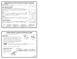
Figure 1. DVS 605 Rear Panel Features — All Models
Power and video input connections Output and control connections
a AC power connector
b Universal analog 15-pin VGA connectors
— inputs 1 and 2
c HDMI connectors — inputs 3-5
(Note: PIP is not available on input 5)
d Audio 5-pole captive screw connectors
— inputs 1- 5 (audio models only)
e
HDMI connector
f
RGB/R-Y,Y, B-Y component 15-pin VGA
connector
g 3G/HD-SDI connector (optional)
(SDI models only)
h Genlock connectors — input and loop
(SDI models only)
i Audio out (fixed), 5-pole captive
screw connector (audio models only)
j RCA audio (S/PDIF) out connector
(audio models only)
k Audio out (variable), 5-pole
captive screw connector
(audio models only)
l Reset button and LED
m RJ-45 LAN connector
n RS-232 and IR 5-pole captive
screw connector
o Contact closure 5-pole captive
screw connector (shares a ground
with RS-232)
DVS 605 • Rear Panel Connections 7

a Power input — Connect the standard IEC power cord from a 100 to 240 VAC,
50‑60 Hz power source into this connector. The front panel control and input
selection buttons light in sequence during power‑up.
b Inputs 1 and 2 — Connect suitable inputs to these two universal analog input ports
(15‑pin HD [VGA] connectors) for auto‑detection of RGB, HD component video, YUVi,
S‑video, or composite video signals.
These universal analog input ports can be configured to accept RGB (RGBHV, RGBs),
component video (bi‑ or tri‑level), S‑video, or composite video signals. The default
setting is for auto detect. The table below shows the pinouts for each format type on
the 15‑pin HD (VGA) connector. The 15‑pin HD supports EDID emulation.
Pinout Table for 15-pin HD Connector
Pin RGBHV RGBs Component S-video Composite
1 Red Red R-Y
2 Green Green Y Luma Video
3 Blue Blue B-Y Chroma
4 No
Connection
No
Connection
5 No
Connection
No
Connection
6 Red Return Red Return R-Y Return
7 Green Return Green Return Y Return L Return Video Return
8 Blue Return Blue Return B-Y Return C Return
9
10 Ground Ground
11 No
Connection
No
Connection
12 EDID/DDC EDID/DDC
13 H Sync C Sync
14 V Sync
15 EDID/DDC EDID/DDC
c Inputs 3 to 5 — Connect HDMI sources to these three HDMI connectors.
Audio from the HDMI inputs can be de‑embeded from the HDMI source. This allows
the user to choose to select audio either from the HDMI inputs or the analog audio
captive screw inputs. Once an audio source is selected, the unselected source is
disabled. The default selection is 2‑channel digital audio from the HDMI inputs.
Connect up to three digital HDMI and DVD‑D inputs to the HDMI connectors
c
.
Connect DVI‑D sources using an adapter cable and secure the connectors to the
DVS using the LockIt
™
bracket as follows:
1. Plug the HDMI cables into the panel connections.
2. Loosen the side HDMI connection mounting screw
from the panel enough to allow the LockIt
lacing bracket to be placed over it.
3. Place the LockIt lacing bracket onto the screw and
slide it up against the HDMI connector. Tighten the
screw to secure the bracket.
4. Loosely place the included tie wrap around the
HDMI connector and LockIt lacing bracket.
15
11
15
3
4
2
1
DVS 605 • Rear Panel Connections 8

5. While holding the connector securely against the lacing bracket, tighten the tie
wrap, then remove any excess length.
The LockIt bracket can also be used in a stacked formation, as shown below.
Side Mounted
Stacked
Figure 2. LockIt Bracket Mounting Options
d Audio inputs 1-5 (audio models only) — Connect audio sources to these 5‑pole
captive screw connectors. Wire the connector for line level, balanced or unbalanced,
analog stereo as shown below.
Balanced Stereo Input
Tip
Ring
Tip
Ring
Sleeves
LR
Unbalanced Stereo Input
Tip
Sleeve
Sleeve
Tip
LR
Figure 3. Audio Input Connector Wiring
NOTE: Control signal ground pins are labeled “G”. Audio ground pins are as .
The wiring and function are the same, whichever way your product is labeled.
e HDMI output — Connect an HDMI display device to this HDMI connector.
NOTE: All video outputs (HDMI, VGA, SDI) share a common output resolution and display
the same content.
f RGB or HD component (R-Y, Y, B-Y) 15-pin HD video output — Connect an RGB
video display or HD component video display to this HD 15‑pin connector.
NOTE: Simultaneous identical scaled outputs for HDMI and analog RGB or HD
component video are available.
g Optional 3G-SDI/HD-SDI output connector — Connect an SDI (serial digital
interface) display to this female BNC connector for SDI output. This complies with
SMPTE 292M and 424M and ITU video digital standards.
NOTE: 3G/HD‑SDI output is only active if the current resolution is set to 720p, 1080i,
1080p, or 2k 23.98/24/25 hz.
h Genlock connector and loop through (SDI models only) — Connect an external
reference signal for synchronization of the SDI output. The loop through can be used
to synchronize additional devices.
DVS 605 • Rear Panel Connections 9

i Audio output (fixed, audio models only) — Connect audio output devices to this
5‑pole, captive screw connector for line level, balanced or unbalanced, analog stereo.
Wire the connectors as shown below.
Balanced Audio Output
Tip
Ring
Tip
Ring
Sleeves
Unbalanced Audio Output
Tip
No Ground Here
No Ground Here
Tip
Sleeves
LR
LR
Do not tin the wires!
Figure 4. Audio Output Connector Wiring
j RCA audio output (S/PDIF, fixed, audio models only) — Plug in an S/PDIF audio
output device into this female RCA connector. This connector outputs digital S/PDIF
audio formats (2‑channel LPCM, Dolby Digital, or DTS).
k Audio output (variable, audio models only) — Connect audio output devices to this
5‑pole, captive screw connector for line level, balanced or unbalanced, analog stereo.
Wire the connectors as shown below.
Balanced Audio Output
Tip
Ring
Tip
Ring
Sleeves
Unbalanced Audio Output
Tip
No Ground Here
No Ground Here
Tip
Sleeves
LR
LR
Do not tin the wires!
Figure 5. Audio Output Connector Wiring
l Reset button and LED — Using an Extron Tweeker, pointed stylus, or ballpoint pen,
press this recessed button for manual resets. The unit has four modes of reset (see
“Resetting the Unit” on page 33 for additional information). The green LED flashes
to show the reset mode indications and that power is on.
m LAN connector — Plug an RJ‑45 jack into this socket to connect the unit to a
computer network. Use a patch cable to connect to a switch, hub, or router.
Wire the connector as shown below.
12345678
RJ-45 Connector
Insert Twisted
Pair Wires
Pins:
Pin
1
2
3
4
5
6
7
8
Wire color
White-green
Green
White-orange
Blue
White-blue
Orange
White-brown
Brown
Wire color
T568A T568B
White-orange
Orange
White-green
Blue
White-blue
Green
White-brown
Brown
Figure 6. RJ-45 LAN Connector Wiring
LAN Activity LED — A blinking yellow LED indicates LAN activity.
Link LED — The green LED lights to indicate a good LAN
connection.
LAN
Activity
Link
DVS 605 • Rear Panel Connections 10

n RS-232/IR port — For serial RS‑232 control, connect a host computer or control
system to the 5‑pole captive screw connector. This port is also a hard wired IR control
for use with an external IR controller.
The default RS‑232 protocol is 9600 baud, 1 stop bit, no parity, 8 data bits, no flow
control.
By default the IR port is disabled. When enbled, the IR port accepts 38 kHz to 1 MHz,
modulated signals at TTL level (0‑5 V)
o Remote contact closure port — For remote input selection of any of the five
inputs, connect a suitable contact closure control device to this 5‑pole captive screw
connector. The contact closure port and the RS‑232 port share a common ground.
DVS 605 • Rear Panel Connections 11

Operation
This section of the manual discusses the operation of a DVS 605 device.
Topics covered include:
• Front Panel Overview
• Powering Up
• The DVS 605 Menu System — Configuration and Adjustments
• Front Panel Lockout (Executive Modes)
• Window vs. Image Size Position — An Overview
• Picture-in-Picture (PIP) Mode
• Other DVS 605 Operating Features
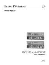
Front Panel Overview
DVS 605
DIGITAL VIDEO SCALER
CONFIG
1 2 3
4 5 PIP
AUTO
SWAP
MENU
NEXT
ADJUST
1
5
3
EXTRON
DVS 605
2
4
6
7
Figure 7. DVS 605 Front Panel Features
a Mini USB configuration port — Connect a control system or computer to this front
panel mini USB port for device configuration, control, and firmware upgrades.
b Input selection buttons and LEDs (1-5) —
Input LEDs — The LED of the selected input lights when the button is pressed. A
blinking LED indicates an audio breakaway input (audio models only).
Inputs 1 and 2 (universal input buttons) — Inputs 1 and 2 select Auto detect, RGB
scaled (RGBHV, RGBS, RGsB), Auto-YUV, RGBcvS, S-video, and composite video inputs.
Inputs 3, 4, and 5 (HDMI/DVI buttons) — Inputs 3, 4, and 5 select HDMI/DVI inputs
c Auto-Image button — Use this to start an Auto-Image function which automatically
sizes and centers an input signal.
d PIP (Picture-In-Picture) button and Swap image button — The PIP button enables
or disables the PIP mode. The Swap button allows the user to swap the two current
inputs displayed in the main and PIP windows.
e LCD display — Displays configuration menus and status information. See “The DVS
605 Menu System — Configuration and Adjustments” section on page 13 for
details.
f Menu navigation buttons (Menu and Next) —
Menu — Use this button to enter and move through the main menu system.
Next — Use this button to step through the submenus of the scaler menu system.
See the “The DVS 605 Menu System — Configuration and Adjustments” section
on the next page for details.
g Adjustment knobs (horizontal [and vertical {) — Using the menu system, rotate
either of these two knobs to scroll through the menu and to make any adjustments.
DVS 605 • Operation 12

Powering Up
When applying power to the DVS 605, the unit undergoes a start‑up self testing sequence
(see image below) and then the LCD displays the default display cycle.
Default Display Cycle
When in use but not in any menu mode, the LCD screen defaults to cycling through the
input/output configuration currently installed. The displayed content may vary, depending
on the input video signal type. See figure 8 for a typical default display cycle.
Figure 8. Typical Default Display Cycle
The default display cycle shows the scaler output rate and refresh rates for the currently
selected input.
The DVS 605 Menu System — Configuration and Adjustments
Scaler configuration and adjustments can be performed by using the embedded web
pages (see “Using Default Web Pages” starting on page 60 ), the Extron Simple
Instruction Set (SIS) of commands (see “SIS Communication and Control” starting on
page 34), or by using the front panel controls and the menus displayed on the DVS unit’s
LCD screen. These menus are used primarily when the scaler is first set up.
Menu Navigation Using Front Panel Controls
Menu button — Press the Menu button to activate menus and scroll through the eight
main menus.
Next button — Press the Next button to move between the submenus of a selected
main menu item.
Adjust ([,{) knobs — In configuration mode, rotate the Adjust horizontal ([) knob
and Adjust vertical ({) knob to scroll through submenu options and to make adjustment
selections. See the flowcharts in this chapter for explanations on knob adjustments.
DVS 605 • Operation 13

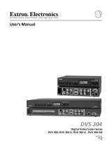
Menu Overview
After start‑up, and when no adjustments are actively being made, the “default cycle”
appears on the LCD. The screens cycle between the screen that shows the number and
video format of the active input and the current output resolution.
Pressing the Menu button once brings up the first of eight main (top level) menus, as
shown below. Each successive press of the Menu button goes to the next main menu.
Menu
Menu
Menu
Menu
Menu
Menu
USER
PRESETS
INPUT
CONFIG
PICTURE
CONTROL
OUTPUT
CONFIG
AUDIO
CONFIG
ADVANCED
CONFIG
VIEW COMM
SETTINGS
EXIT MENU?
PRESS NEXT
Menu
Menu
Menu
Menu
Next
Next
2
sec.
2
sec
.
Default Displa
y
Cy
cle
IN
R
G
BHV
#
1
640
x
480
IN
3
1.47 kH
z
#1 59.94 H
z
OU
TP
U
T
720p
@
6
0
2
sec.
Figure 9. Top Level Menus
A fourth default cycle menu appears only when genlock is enabled. See “Genlock/AFL
Mode”on page 20) for details.
NOTE: From any menu or submenu, after 20 seconds of inactivity the DVS will save
all adjustment settings and time‑out to the default cycle.
The flowchart shown on page 15 provides an overview of the complete menu system,
with configuration submenus and the options for each setting. In the flow charts the use
of “x”, (for example in (x) or Inx) indicates an input number.
Use the Menu button to scroll between top level menus and press Next to enter the
submenus.
NOTE: If no signal is present on the currently selected input, NO SIGNAL appears in
place of the input type. For example, INPUT 4 NO SIGNAL.
Details of each of the menus are on subsequent pages after the main flow chart.
DVS 605 • Operation 14
/