
412(A455)

CONTENTS
Product Features and Specifications .................................................... 1
Installation Requirement …………………………………………………………………………….. 3
Steps of Installation …........................................................................7
Exploded View .................................................................................36
Test Run ………..................................................................................40
Operation Instruction .......................................................................42
Maintenance ...................................................................................43
Trouble Shooting .............................................................................43
Four-Post Lift Parts List .............................................. .....................44

1
I. PRODUCT FEATURES AND SPECIFICATIONS
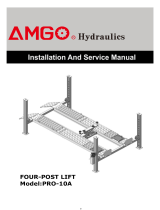
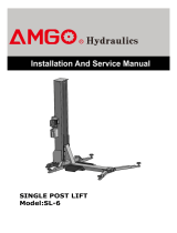
4-POST LIFT MODEL 412(A455) FEATURES
· Electro-air control operation system.
· Mechanical self-lock and air-drived safety release.
· Electrical hydraulic power system, cable-drived.
· Adjustable platform and adjustable safety lock ladders.
· Optional Jack: With hand pump/Air-operated hydraulic pump/Controlled by power unit.
Fig. 1
MODEL 412(A455) SPECIFICATIONS
II. INSTALLATION REQUIREMENT
Model
Lifting
Capacit
y
Lifting
Height
Lifting
Time
Overall Length
(Inc. Ramps)
Overall Length
(No Ramps)
Overall
Width
Width
Between
Columns
Gross
Weight
Motor
412(A455)
5.5T
1865mm
60S
6012mm
5100mm
3208mm
2852mm
1126Kg
4.0HP
12,000
lbs
73 1/2”
236 5/8”
200 3/4”
126 1/4”
112 1/4”
2420 lbs

2
A. TOOLS REQUIRED
Rotary Hammer Drill (Φ19)
Hammer
Level Bar
English Spanner (12")
Ratchet Spanner With Socket (28
#
)
Wrench set
Carpenter’s Chalk
Screw Sets
Tape Measure (7.5m)
Pliers
Socket Head Wrench (3
#
, 5
#
, 6
#
)
Lock Wrench
(10
#
, 12
#
, 13
#
, 14
#
, 17
#
, 19
#
, 24
#
, 30
#
)
B. SPECIFICATIONS OF CONCRETE (See Fig. 3)
Fig. 2

3
Specifications of concrete must be adhered to the specification as following.
Failure to do so may result in lift and/or vehicle falling.
1. Concrete must be thickness 100mm minimum and without reinforcing steel bars,
and must be dried completely before the installation.
2. Concrete must be in good condition and must be of test strength 3,000psi
(210kg/cm²) minimum.
3. Floors must be level and no cracks.
C. AIR SUPPLY
Air pressure requirement: 0.5Mpa~0.8Mpa, Air line size
¢
8
×¢
6 and
¢
6
×¢
4.
D. POWER SUPPLY
The electrical source must be 3KW minimum. The source cable size must be 2.5mm²
and in good condition of contacting with floor.
III. STEPS OF INSTALLATION
A. Location of Installation
Check and insure the installation location (concrete, layout, space size etc.) is
suitable for lift installation.
B. Check the parts before assembly
1. Packaged lift and Hydraulic Power Unit (See Fig. 4).
2. Open the outer packing carefully (See Fig. 5).
Fig. 4
Fig. 3
≥100mm

4
Shipment Parts List
3. Take off the drive-in ramps and columns (See Fig. 6).
4. Loose the screws of the upper package stand, take off the offside platform, take out
the parts inside the powerside platform, than remove the package stand.
5. Move aside the parts and check the parts according to the shipment parts list
(See Fig. 7).
6. Open the carton of parts and check the parts according to the parts box list
Control box
Powerside Platform
Drive-in Ramp
Offside Platform
Cross Beam
Column
Fig. 5
Fig. 6
Parts box
Fig. 7
69

5
(See Fig. 8).
7. Check the parts of the parts bag according to the parts bag list (See Fig. 9).
Fig. 9
Fig. 8

6
C. Use a carpenter’s chalk line to establish installation layout as per Table 1
Make sure the size is right and base is flat (see Fig. 10).
Note: Reserve space front and behind the installation site.
Table 1
MODEL
A
B
C
412/A455
5100mm
200 3/4”
3208mm
126 1/4”
6025mm
237 1/4”
Use a carpenter’s chalk line to
establish installation layout
Car in Direction
Fig. 10

7
D. Install cross beams (See Fig. 11, Fig. 12).
1
Fig. 11
2
3
3
Hole towards inside
Fig. 12

8
E. Fix the anchor bolts
1. Prepare the anchor bolts (See Fig. 13).
2. Using the prescribed rotary hammer drill, and drill all the anchor holes and install
the anchor bolts. Do not tighten the anchor bolts (See Fig. 14).
Note: Anchor bolts driven into the ground at least 90mm
F. Install the safety ladders
1. Take off the pulley safety cover and unscrew the four upper nuts of the safety ladders,
and then adjust the four lower nuts to be at the same position. Withdraw the
slack-cable safety lock of the cross-beam to insert the safety ladder in, raise the
safety ladder, and screw the upper nuts (See Fig. 15).
Nut
Lock washer
Washer
Fig. 13
Fig. 15
Fig. 14
Drilling
Expand
Clearing
Safety ladder is inserted between
limit pins of the cross-beam
5
Safety
Ladder
Limit Pin
Limit Pin
6
Safety ladder is
inserted between
limit pins
90mm

9
2. Install safety ladders (See Fig. 16).
G. Put the cross beams at the same height (See Fig. 17).
Safety ladder pass through
the hole of the top plate,
then tighten the two nuts
Fig. 16
Fig. 17
This height should be
the same for four
safety ladders
6
7
Lifting both cross beams to the
same height, it is recommended
to about 1 meter height
The four primary safety
locks are adjusted to be
locked to the safety
ladders at the same time

10
H. Install powerside platform.
1. Put the powerside platform upon the cross beams by fork lift or manual, offset the
cross beams to the outside till the pulleys of both platforms can set up into the cross
beams (See Fig.18), Install the powerside platform and screw up the bolts(See Fig.19).
Fig. 18
Offset the cross beam lean
outward when putting the
powerside platform on the
cross beams
Offset the cross beam
lean outward when
putting the powerside
platform on the cross
beams
Fig. 19
8
Fix platform and cross beam
together with hex bolt
M16*40

11
I. Assembly offside platform and slider block, check the plumbness of columns with
level, adjusting with the shims if not, and then tighten the anchor bolts (See Fig. 20).
Note: The tightening torque for the anchor bolt is 150N.m
Fig. 20
Using the Ratchet spanner with
socket to tighten the bolts
Install the slider block
on the cross beam
8
18
3-15
3-16
3-14

12
J. Install cables (See Fig. 21).
1. Pass through the cables from the platform to the columns according to the number of
the cables.
NO.
Cable
①
②
③
④
Length
(inc. connecting fitting)
3749mm
147 5/8”
10260mm
404”
5350mm
210 5/8”
8654mm
340 3/4”
Fig. 21
72
70
71
73
B
C
A
D
D
A
C
B

13
2. The cable pass through the cross beam to top plate of columns and be screwed with
cable nuts (See Fig. 22).
7
Cable pass through
between the big pulley
and tension pulley
Cable pass through top
plate and be screwed
with cable nuts.
Fig. 22
Install steel cable limit pin
Cable
60C
Pulley
60B
Installed drawing
cable
limit pin

14
3. Illustration for platform cables (See Fig. 23).
cable ①
cable ②
cable ④
cable ②
cable ③
cable ④
cable ②
Fig. 23
Hex Bolt M10*120
cable ④
19
Cable
○
4
Cable
○
2
Cable
○
2
Cable
○
1
Cable
○
4
Cable
○
3
Slide block

15
K. Install oil-water separator, air solenoid valve, control box and power unit
1
.
For Electric control air-operated four post lift (See Fig. 24).
Oil-water separator and
Air Solenoid Valve
Fig. 24
68
Air outlet
Air inlet
1
20
21
31
33
22
23
24
25
26
27
28
29
32
30
22
34
202
36
37
38

16
L. Install hydraulic system (See Fig. 25).
Note: Oil hoses and oil return pipe connected to oil cylinder must be passed above
the cable and cylinder inlet port must swing upward to avoid the oil hose and
oil return pipe scratched by cable.
d
c
b
a
retainer
Protective Ring
Fig. 25
86
63
78
80
79
a
b
c、d
74
86
75
81
82A
76
86
76
77
78
cylinder inlet
port swing upward

17
M. Install air-line system
1. Cut the air hose(
¢
6
×¢
4 ) between two clips on cross beam, and then connect to
T-fitting.( See Fig.26)
2.. Connecting front and rear cross beam using ¢6×¢4 black air line (See Fig. 27).
3. Connecting air solenoid valve using ¢6×¢4 black air line (See Fig. 27).
Front
Cross Beam
Air cylinder fitting
Air cylinder fitting
Air cylinder fitting
Air cylinder fitting of
powerside column
Connecting Air Solenoid
valve using ¢6×¢4
black air line.
F
ig. 27
Rear
Cross Beam
Powerside platform
83
Retainer
retainer
Fig.26
83
Cut the air hose between
two retainers and connect
to T-fitting
Rear
Cross Beam
Front
Cross Beam
Air cylinder fitting
Powerside platform
86A
84
85
86A
Protective
ring
Air cylinder fitting of
powerside column

18
4. Connecting oil-water separator and air solenoid valve using air line (See Fig. 28).
4. Connecting air inlet (air supply pressure 5kg/cm
2
- 8kg/cm
2
), adjusting the air
pressure of oil-water separator to 0.4 - 0.6MPa (See Fig. 29).
Fig. 29
Clockwise to increase the air
pressure
Counter-clockwise to reduce
the air pressure
Adjusting the air pressure to
0.4~0.6MPa
Connecting
air inlet
87
Connecting Oil-water
separator and Air solenoid
valve using black air line
¢8×¢6×180mm
Oil-water
separator
Air solenoid valve
air line ¢6×¢4
Fig. 28
Page is loading ...
Page is loading ...
Page is loading ...
Page is loading ...
Page is loading ...
Page is loading ...
Page is loading ...
Page is loading ...
Page is loading ...
Page is loading ...
Page is loading ...
Page is loading ...
Page is loading ...
Page is loading ...
Page is loading ...
Page is loading ...
Page is loading ...
Page is loading ...
Page is loading ...
Page is loading ...
Page is loading ...
Page is loading ...
Page is loading ...
Page is loading ...
Page is loading ...
Page is loading ...
Page is loading ...
-
 1
1
-
 2
2
-
 3
3
-
 4
4
-
 5
5
-
 6
6
-
 7
7
-
 8
8
-
 9
9
-
 10
10
-
 11
11
-
 12
12
-
 13
13
-
 14
14
-
 15
15
-
 16
16
-
 17
17
-
 18
18
-
 19
19
-
 20
20
-
 21
21
-
 22
22
-
 23
23
-
 24
24
-
 25
25
-
 26
26
-
 27
27
-
 28
28
-
 29
29
-
 30
30
-
 31
31
-
 32
32
-
 33
33
-
 34
34
-
 35
35
-
 36
36
-
 37
37
-
 38
38
-
 39
39
-
 40
40
-
 41
41
-
 42
42
-
 43
43
-
 44
44
-
 45
45
-
 46
46
-
 47
47


PEAK 412 Installation and Service Manual
- Type
- Installation and Service Manual
- This manual is also suitable for
Ask a question and I''ll find the answer in the document
Finding information in a document is now easier with AI
Related papers
-
PEAK AMGO A440 Installation and Service Manual
-
PEAK X400A Installation and Service Manual
-
-
-
-
PEAK AMGO PX12A Installation and Service Manual
-
Other documents
-
 AMGO PRO-10A Installation and Service Manual
-
 AMGO Hydraulics SL-6 Installation and Service Manual
-
Black Widow BW-1000A-SIDE User manual
-
BendPak XPR-7TR Owner's manual
-
 AMGO 209X Installation and Service Manual
-
Atlas 90HSC Installation & Operation Manual
-
LAUNCH TLT250AT(C) User manual
-
WEATHER GUARD SPJ-100 User manual
-
Werner 6004 User manual
-
Werner MTIAA-13 User manual


