Page is loading ...

S pumps, range 72 - 74 - 78
DIN 50/60 Hz
Service instructions
GRUNDFOS INSTRUCTIONS

English (GB)
2
English (GB) Service instructions
Original service instructions.
CONTENTS
Page
1. Symbols used in this document
1. Symbols used in this document
2
2. Servicing S pumps with explosion-proof motors
3
3. Safety
3
4. Identification
3
4.1 Nameplate
3
4.2 Type key
4
5. Handling the pump
6
5.1 Lifting the pump
6
5.2 Lifting points
6
5.3 Raising pump to upright position
6
6. Torques, lubricants and special liquids
7
6.1 Common torques
7
6.2 Special torques and lubricants
7
6.3 Quantities of grease in bearings
7
6.4 Special liquids
7
7. Service tools
8
7.1 Standard tools
8
7.2 Special tools
9
7.3 Tightness test tools
9
7.4 Lifting tools
9
8. Service
10
8.1 General information
10
8.2 Pump cleaning and visual inspection
10
8.3 Annual maintenance
10
8.4 Oil check and oil change
11
8.5 Inspection and adjustment of impeller clearance
12
9. Dismantling and assembly instructions
13
9.1 Checking and replacing the cable
13
9.2 Replacing the terminal board
14
9.3 Replacing the protection sensors
17
9.4 Dismantling range 72
19
9.5 Assembling range 72
21
9.6 Dismantling range 74
23
9.7 Assembling range 74
25
9.8 Dismantling range 78
29
9.9 Assembling range 78
30
10. Tightness tests
32
10.1 Tightness test of stator (submerged)
32
10.2 Tightness test of terminal box (cable side, submerged)
32
11. Drawings
33
11.1 Range 72
33
11.2 Range 74
42
11.3 Range 78
48
11.4 Position numbers and material specification
56
11.5 Sensor positions
58
11.6 Electrical connections
60
Warning
If these safety instructions are not observed,
it may result in personal injury.
Warning
These instructions must be observed for
explosion-proof pumps. It is advisable also to
follow these instructions for standard pumps.
Warning
If these instructions are not observed, it may lead
to electric shock with consequent risk of serious
personal injury or death.
Warning
The surface of the product may be so hot that
it may cause burns or personal injury.
Warning
The sound pressure level is so high that hearing
protection must be used.
Caution
If these safety instructions are not observed,
it may result in malfunction or damage to the
equipment.
Note
Notes or instructions that make the job easier
and ensure safe operation.

English (GB)
3
2. Servicing S pumps with explosion-proof
motors
S pumps, range 72 to 78 have the following explosion protection
classification:
Service work on Ex pumps must be carried out by Grundfos or a
workshop authorised by Grundfos. Violation of this requirement
will invalidate the Ex classification of the pump.
Overhauled and repaired explosion-proof pumps are provided
with a repair plate giving the following information:
• the repair symbol R
• name of registered trade mark of the repairing workshop
• workshop reference number relating to the repair
• date of overhaul or repair.
In case of subsequent repairs, the existing repair plate should be
replaced by a new, updated repair plate and earlier markings
must be recorded.
The repairing workshop must keep records of performed
overhauls and repairs together with records of all previous
overhauls, repairs and possible modifications. Copies of the
repairing workshop’s detailed records should be filed by the
owner or operator together with the original type certificate of the
explosion-proof motor in question.
3. Safety
For safety reasons, all work in pits must be supervised by a
person outside the pump pit.
Pits for submersible sewage and wastewater pumps contain
sewage and wastewater with toxic and/or disease-causing
substances. Therefore, all persons involved must wear
appropriate personal protective equipment and clothing, and all
work on and near the pump must be carried out under strict
observance of the hygienic regulations in force.
If Grundfos is requested to service the pump, Grundfos must be
contacted with details about the pumped liquid, etc., before the
pump is returned for service. Otherwise Grundfos can refuse to
accept the pump.
Possible costs of returning the pump are paid by the customer.
However, any application for service (no matter to whom it may
be made) must include details about the pumped liquid if the
pump has been used for liquids which are injurious to health or
toxic.
4. Identification
4.1 Nameplate
Fig. 1 Pump nameplate
All pumps can be identified by means of the nameplate on the
motor top cover, see fig. 1.
72
Direct drive, 50 or 60 Hz CE 1180 II2 G Ex bc d IIB T4
Frequency converter
drive
CE 1180 II2 G Ex bc d IIB T3
74, 78
Direct drive, 50 or 60 Hz Only on request
Frequency converter
drive
Only on request
Warning
Pump installation in pits must be carried out by
specially trained persons.
Work in or near pits must be carried out
according to local regulations.
Warning
Before attempting to lift the pump, make sure the
rated capacity of the lifting equipment (lifting
chain etc.) is adequate for the lifting work.
The rated capacity of the lifting equipment is
stated on the equipment nameplate. The weight
of the pump is stated on the pump nameplate.
Note
If a pump has been used for a liquid which is
injurious to health or toxic, the pump will be
classified as contaminated.
TM05 8220 2113
Pos. Description
1 Type designation
2 Product number
3 Serial number
4 Maximum head (m)
5 Number of phases
6 Voltage, delta connection
7 Voltage, star connection
8 Rated power input (kW)
9 Power factor (Cos φ)
10 Production code (YYWW)
11 Model
12 Maximum liquid temperature
13 Maximum flow rate (l/s)
14 Enclosure class according to IEC 60529
15 Frequency (Hz)
16 Rated speed
17 Current, delta connection
18 Current, star connection
19 Rated power output P2
20 Insulation class
21 Weight

English (GB)
4
4.2 Type key
All S pumps, range 72, 74 and 78, described in this product guide are identified by the type designation stated in the confirmation of order
and other documentation supplied with the pump.
Please note that the pump type described in this type key is not necessarily available in all variants.
Code Example S 2 .90 .250 .2250 .4 .72 S .C .496 .G .N .D .5 13 .Z
S
ST
Pump type:
Grundfos sewage and wastewater pump
Multi-channel impeller pump installed in a column pipe
2
3
4
Impeller type:
Two-channel
Three-channel
Four-channel
Pump passage:
Maximum solids size [mm]
250
[ ]
Pump discharge, S type:
Nominal diameter of pump discharge port [mm]
Pump discharge, ST-type:
Nominal diameter of column pipe [mm]
Output power, P2:
P2 = Code number from type designation/10 [kW]
4
6
8
10
12
14
Number of poles:
4-pole motor
6-pole motor
8-pole motor
10-pole motor
12-pole motor
14-pole motor
72
74
78
Pump range:
72
74
78
S
H
M
L
E
F
Pressure version:
Super-high
High
Medium
Low
Extra-low
Super low
S
C
D
H
Installation type:
Submerged installation without cooling jacket
Submerged installation with cooling jacket
Dry installation with cooling jacket
Dry horizontal installation with cooling jacket
Impeller diameter (average):
[mm]
G
Q
Material code for impeller, pump housing and stator housing:
Cast iron impeller, pump housing and stator housing
Cast iron pump with stainless steel impeller
N
Ex
Pump version:
Non-explosion-proof pump
Pump with explosion-proof motor
B
D
Sensor version:
S pump with built-in SM 113 module. PTC sensors are connected directly to IO 113 or other PTC relay.
S pump without built-in SM 113 module
5
6
Frequency:
50 Hz
60 Hz
11
13
18
58
1G
1H
1B
1D
Voltage and connection:
50 Hz 60 Hz
3 x 400 / 690 V Y/D 3 x 575 / (996) V Y/D
3 x 415 / 719 V Y/D
3 x 380-400 / 660-690 V Y/D
3 x 380 / 660 V Y/D 3 x 380 / 660 V Y/D
3 x 460 / (797) V Y/D
3 x 400-415 / 690-719 V Y/D
3 x 380-415 / 660-719 V Y/D
Z Custom-built products

English (GB)
5
Type key used for frame size 74 and 78 until 2010. May still be used for spare pumps manufactured later.
Code Example S 2 X 250 4 H 2 5 11 Z
S
Pump type:
Grundfos (or Sarlin) wastewater pump/sewage pump
2
3
4
A
N
Impeller type:
Two-channel
Three-channel
Four-channel
Axial Propeller
Multi-channel, small pump passage
[ ]
X
Pump version:
Standard pump
In conformity with the ATEX directive
100
Power:
Motor power in kW
2
4
6
8
10
12
14
Number of poles:
2-pole motor
4-pole motor
6-pole motor
8-pole motor
10-pole motor
12-pole motor
14-pole motor
[ ]
A
B
Pump generation:
First generation
Second generation
Third generation
[ ]
S
H
M
L
F
Pressure version:
No classification
Super high
High
Medium
Low
Super extra low
1
2
3
4
5
6
7
Installation type:
Submerged installation without cooling jacket
Submerged installation with cooling jacket
Dry installation with cooling jacket
Submerged installation, portable. Pump without cooling jacket.
Submerged installation, portable. Pump with cooling jacket.
Dry horizontal installation with base stand and bracket. Pump with cooling jacket
Submerged column installation
[ ]
A,B,C
Interchangeability:
No letter indicates full interchangeability of parts and use of the same spare parts catalogue.
The letters (A, B, C...) indicate interchangeability of parts between otherwise identical pumps.
1
[ ]
Number of phases:
Single-phase
Three-phase
5
6
Frequency:
50 Hz
60 Hz
06
10
11
12
13
14
15
Voltage and starting method:
50 Hz 60 Hz
660-690 V Y
288-500 V Y/D
400-690 V Y/D 460-(796) V Y/D
220-380 V Y/D
415-(719) V Y/D
500-(865) V Y/D
380-660 V Y/D
U
Special equipment:
Flanges sized according to ANSI specifications
D
C
Z
Non-standard parts:
Special diameter in impeller
Special length of cable
Combination of C and D or other special part
R
S
Q
Material code for impeller, pump and stator housing:
Stainless steel impeller, pump housing and stator housing, AISI 316 (DIN W.-Nr. 1.4408)
Stainless steel impeller and pump housing, AISI 316 (DIN W.-Nr. 1.4408)
Stainless steel impeller, AISI 316 (DIN W.-Nr. 1.4408)

English (GB)
6
5. Handling the pump
S pumps, range 78 weigh up to 7800 kg without accessories. It is
therefore very important to use the right lifting equipment.
The pump weight is stated on the pump nameplate. See section
4.1 Nameplate.
5.1 Lifting the pump
All lifting equipment must be rated for the purpose and checked
for damage before any attempt to lift the pump. The lifting
equipment rating must under no circumstances be exceeded.
See section 7.4 Lifting tools.
5.2 Lifting points
Fig. 2 Lifting points, range 72
Fig. 3 Lifting points, range 74 and 78
5.3 Raising pump to upright position
Fig. 4 Raising the pump to upright position, step 1
Fig. 5 Raising the pump to upright position, step 2
Fig. 6 Raising the pump to upright position, step 3
Warning
Never lift the pump by the power supply cables.
It may result in electric short-circuit and risk of
electric shock when the pump is connected to the
mains. The cables and cable entry may be
damaged, leading to loss of watertightness and
consequent severe damage to the motor.
TM03 4459 0208TM04 6068 4809
Warning
Make sure that the lifting brackets are tightened
before attempting to lift the pump. Tighten if
necessary. Carelessness during lifting or
transportation may cause injury to personnel or
damage to the pump.
TM03 3034 0208TM03 3035 0208TM03 3036 0208

English (GB)
7
6. Torques, lubricants and special liquids
This section shows the screws and nuts that must be tightened to a certain torque and the lubricants to be used.
6.1 Common torques
6.2 Special torques and lubricants
Oils:
Silicone spray Valvoline: 96249498.
Esso Unirex S2: 96248520/SKF LGHP 2 (-).
Motor oil with viscosity grade SAE 10 W 30 or SAE 10 W 40.
6.3 Quantities of grease in bearings
6.4 Special liquids
Würth Ergo 4307 or similar (thread-locking compound)
Henkel Loclite 290 or similar (thread-locking compound)
ACC Silicone Silcoset 151 (glue, FM approved).
Dimension M8 M10 M12 M16 M20 M24 M27 M30
Torque [Nm] 20 40 70 170 330 570 820 1120
Range Pos. Description Quantity Dimension
Torque
[Nm]
Lubricant
74, 78 61a O-ring (primary shaft seal) 2 - - Oil
74, 78 62 O-ring 1 - - Oil
72, 74 67 Screw (impeller) 1 M24 600 Oil
78
67 Screw (impeller) 1 M24 160 Oil
67a Screw (fastening plate of impeller) 3 - 170 Oil
All 72a O-ring 1 - - Oil
All 105
O-ring (inside of stationary part) 1 - - Oil
Primary shaft seal (sliding surfaces) 1 - - Silicone spray
72 105 Screw of primary shaft seal 5 - 8 -
74, 8 105 Screw of primary shaft seal 5 - 15 -
All 105b
O-ring (inside stationary part) 1 - - Oil
Secondary shaft seal (sliding surfaces) 1 - - Silicone spray
72, 74 105b Screw of secondary shaft seal 5 - 8 -
78 105b Screw of secondary shaft seal 5 - 15 -
74, 78 153 Angular contact ball bearings 2 - - Unirex S2 / LGHP 2
All 157 O-ring 1 - - Oil
All 157a O-ring 1 - - Oil
All 162 Roller bearings 1 - - Unirex S2 / LGHP 2
All 154 Ball bearing 1 - - Unirex S2 / LGHP 2
All 193 Oil plug 3 R 3/4 55 ± 5 -
74, 78 756 O-ring 1 - - Oil
Range Bearing Amount of grease
72
Lower bearings
2.2 litres
74 2.3 litres
78 4.2 litres
Range Bearing Amount of grease
72
Upper bearing
0.28 litres
74 1.0 litres
78 1.7 litres
Range Pos. Component Liquid
All
523 Cable gland for WIO Ergo 4307
520d Moisture switch Loclite 290
177 Terminal board Silcoset 151

English (GB)
8
7. Service tools
The following sections shows tools for pump service.
7.1 Standard tools
Standard tools
ABCD
EFGH
IJKL
MN
Pos. Range Designation Description Part number
A All Pinch bar - SV5201
B All Screwdriver Straight slot -
C All Lock-ring pliers - SV2014
D All Plastic hammer - SV0349
E
72 Hook spanner (Walter) 120-130 mm -
74 Hook spanner (SKF) HN22 -
78 Impact spanner (TMFN) 30-40 -
F All Warm-air heater - -
G All Multimeter - -
H All Ratchet handle 1/2" - 96777072
I All Hexagon head driver
4 mm SV0414
M6 - 5 mm SV0296
M8 - 6 mm SV0297
M10 - 8 mm SV0298
M12 - 10 mm SV0299
M16 - 12 mm - 1/2" SV0394
J All Ring/open-end spanner
8 mm SV0273
10 mm SV0083
12 mm SV0274
16 mm SV0185
20 mm -
24 mm SV0122
27 mm SV0084
30 mm SV0073
K All Puller for bearing - SV0335
L All Sliding gauge 0-150 mm SV0307
M All Cable pliers - -
N All Feeler gauge - -

English (GB)
9
7.2 Special tools
Special tools
7.3 Tightness test tools
Tightness test tools
7.4 Lifting tools
Lifting tools
OPQR
STUV
Pos. Range Designation Description Part number
O All Torque wrench - -
P 74 Seal assembly tool (PUR127) Roplan 85 mm 96242908
Q 74 Seal assembly tool (PUR128) Roplan 95 mm 96242909
R 78 Seal assembly tool (PUR129) Roplan 110 mm 96242910
S 78 Seal assembly tool (PUR130) Roplan 110 mm 96242911
T 74 Seal assembly tool (PUR131) Roplan 100 mm 96242912
U 78 Seal assembly tool (PUR132) Roplan 120 mm 96242913
V 72 Seal assembly tool (PUR133) Roplan 65 mm 96255372
WXY
BAR
Pos. Designation Description Part number
W Pressure gauge --
X Test plug (KOE045)
Connector M3\8-24 UNF F-ISO
228-G 3\8M
96061209
Y Test plug (KOE171) Connector R3/4 96061213
AA BB CC DD
Pos. Designation Description Part number
AA Eyebolt with rotating swivel Range 74 and 78 -
BB Shackle All -
CC Eye bolt All -
DD Lifting clamp Range 78 98253177

English (GB)
10
8. Service
8.1 General information
Service must be carried out by specially trained persons.
Before carrying out maintenance and service, it must be ensured
that the pump has been thoroughly flushed with clean water.
Rinse the pump parts with water after dismantling.
Before assembly:
• Clean and check all parts.
• Replace defective parts with new parts.
• Order the necessary service kits.
• Gaskets and O-rings should always be replaced when the
pump is overhauled.
During assembly:
• Lubricate and tighten screws and nuts to correct torque as
stated in section.
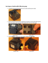
8.2 Pump cleaning and visual inspection
A simple maintenance measure is to clean the pumps at regular
intervals. The pumps may be cleaned on site at the pumping
station when lifted up from the wet pit. Hose down the pump
externally using a high-pressure jet cleaner (maximum pressure
100 bar). Caked dirt on the motor must be removed to ensure
good heat conductivity. A mild detergent approved for disposal
into the sewage system may be used. The pumps may be
scrubbed, using a soft brush, if necessary.
Visual inspection of the pump should include search for cracks or
other external damage. Inspect the lifting bracket and lifting chain
for wear and corrosion. Inspect the pump cable for cracks or
lacerations in the sheath, kinks or other damage. Inspect visible
parts of the cable entry for cracks and for being firmly connected
to the motor top cover. Check all visible screws and tighten, if
necessary.
The air vent valve at the top of the cooling jacket may be removed
and cleaned, if necessary. Clean the vent hole before refitting the
valve after cleaning.
8.3 Annual maintenance
Pumps in normal operation should be inspected once a year.
If the pumped liquid is very muddy or sandy, check the pump at
shorter intervals.
The following points should be checked:
• Power consumption
See section 4.1 Nameplate.
• Oil level and oil condition
See section 8.4 Oil check and oil change.
• Cable entry
Make sure that the cables are not sharply bent or pinched.
Replace the cables if necessary.
See section 9.1 Checking and replacing the cable.
• Sensors
Make sure that sensor are working. Replace the sensors if
necessary.
See section 9.3 Replacing the protection sensors
• Impeller clearance
Check the impeller clearance.
See section 8.5 Inspection and adjustment of impeller
clearance.
• Pump parts
Check the pump housing, etc. for possible wear.
Replace defective parts.
• Ball bearings
Check the shaft for noisy or heavy operation (turn the shaft by
hand). Replace defective ball bearings.
A general overhaul of the pump is usually required in case of
defective ball bearings or poor motor function. This work must
be carried out by an authorized service workshop.
• O-rings and similar parts
During service / replacement, it must be ensured that the
grooves for O-rings and seal faces have been cleaned before
the new parts are fitted.
Warning
Before starting work on the pump, make sure that
the mains switch has been locked in position 0.
All rotating parts must have stopped moving.
Warning
Except for replacement/dismantling of bearings,
all other service work must be carried out by
Grundfos or an authorised service workshop.
Warning
On Ex pumps, the ball bearings must only be
replaced by an authorised Ex workshop.
Note
Used rubber parts must not be reused.

English (GB)
11
8.4 Oil check and oil change
The oil chamber is filled with oil acting as lubricant and coolant for
both mechanical shaft seals.
Low oil level may indicate that the upper mechanical shaft seal is
defective. Contact an authorized service workshop for further
overhaul of the pump and repair, if required.
The oil in the oil chamber can be changed with the pump in either
horizontal or upright position.
Horizontal position
Proceed as follows:
1. Place the pump in such a position that inspection screw A is
pointing upwards.
Fig. 7 Pump with inspection screw A upwards
2. Place a clean container under the pump to collect all the
drained-off oil. Remove screw B and observe the oil level.
3. Check the oil level and take an oil sample to inspect the
condition of the oil. The oil becomes greyish white like milk if it
contains water. In normal operation a small leakage through
the mechanical shaft seals is expected to happen, but if the
water content in the oil is high, this may be the result of a
defective shaft seal. The oil should be changed if it contains
water.
4. If the oil needs to be changed, remove screw C and allow all
the oil to drain from the chamber into the container. Pour an
oil sample into a glass container and observe the condition of
the oil.
Clear oil can be reused.
Emulsified oil must be changed and disposed of.
5. Replace the O-rings, refit screw C and tighten securely.
Fill the oil chamber with oil to the correct level. Refit screws A
and B and tighten securely.
Upright position
Proceed as follows:
1. Identify the screws A, B and C and their positions relative to
each other. See fig. 7.
Fig. 8 Correct oil level of upright pump
2. Proceed as above and use screw B again for indication of the
level of oil in the oil chamber. See fig. 8.
3. When the pump is upright, the oil has to be pumped out of the
oil chamber. Use a suction pump with a flexible suction hose
that can be inserted deep into the oil chamber.
4. Pump out the oil using all the screw holes in turns so as to
reach all sections of the interior of the oil chamber. Collect the
drained oil in a clean container.
5. Replace the O-rings, refit screw C and tighten securely.
Fill the oil chamber with oil to the correct level. Refit screws A
and connecting block B and tighten securely.
Note
Check the oil regularly to avoid damage and
breakdown of the pump.
Warning
Lack of oil may cause overheating and damage of
the mechanical shaft seals. The WIO sensor in
the oil chamber will trip the alarm if the oil quality
is poor or there is not enough oil in the oil
chamber.
Note
Use oil with viscosity grade SAE 10 W 30 or SAE
10 W 40.
Range
Oil quantity
Installation type
S C and D ST
72 25 litres 18.5 litres 25 litres
74 - 20 litres 25 litres
78 - 80 litres 80 litres
TM03 1628 2705
Warning
When slackening the screw A of the oil chamber,
note that pressure may have built up in the
chamber. Do not remove the screw until the
pressure has been fully relieved!
Note
Used oil must be disposed of in accordance with
local regulations.
TM04 6924 1210
Warning
When slackening the screw A of the oil chamber,
note that pressure may have built up in the
chamber. Do not remove the screw until the
pressure has been fully relieved!
Note
Used oil must be disposed of in accordance with
local regulations.
B

English (GB)
12
8.5 Inspection and adjustment of impeller clearance
Position numbers of parts (digits) refer to section 11. Drawings
and section 11.4 Position numbers and material specification.
The correct impeller clearance is 1.3 mm ± 0.2 mm.
The clearance should be reset if it is 2.0 mm or more.
The method for resetting the clearance is different for dry-
installed pumps, type D, and submersible pumps, types S and C.
For dry-installed pumps there are two methods. All methods are
described here.
8.5.1 Submersible pumps, installation types S, C and ST
Submersible pumps have a separate adjustable pump suction
cover which may be shaped as a suction bell. When the pump is
installed or withdrawn, locate the six fastening screws of the
suction cover and the three set screws.
Use a feeler gauge (N) to check the clearance between the
impeller and the suction cover all around the perimeter of the
suction opening. See fig. 9.
If the clearance needs adjustment proceed as follows:
1. Slacken all fastening screws (35) and set screws between
suction cover and pump housing.
2. Use a rubber mallet to tap the suction cover to close the
clearance.
3. Open the clearance to specified value by turning the three set
screws (12c).
4. Check that the clearance is uniform around the perimeter of
the suction opening.
5. Tighten the fastening screws (35) and check that the
clearance is stable.
6. Turn the impeller (49) by hand and check at several points.
Fig. 9 Impeller clearance, installation types S, C and ST
8.5.2 Dry-installed pumps, installation types D and H
The impeller clearance can be inspected and set with the pump
installed on the pump stand and connected to the pipework.
In these pumps, the suction cover is located between pump
housing and outer connection flange on the suction side of the
pump.
Depending on the construction, there are two ways to set the
impeller clearance.
Method 1
Fig. 10 Impeller clearance, installation types D and H,
method 1
These pump types have threaded holes for the fastening screws
(35) of the suction cover (12a) in the pump housing (50) as shown
in fig. 10. Set the impeller (49) clearance as follows:
1. Slacken the three set screws (12c) and close the impeller
clearance "S" by tightening the six fastening screws (35)
diagonally to move the suction cover evenly.
2. Measure the distance "L" between suction cover and pump
housing at three points, next to the set screws, using feeler
gauges or callipers and make a note of the distance.
3. Slacken the fastening screws and draw back the suction cover
by 1.3 mm ± 0.2 mm using the three set screws (approx. one
150 ° turn of an M27 set screw) and the distance "L" as
reference.
4. Tighten all fastening screws and check that the distance "L" at
the three reference points is stable on the new value.
Warning
Never work under a pump when it is hanging
from hoist!
Note
Before adjusting the clearance, clean the gap
between impeller and suction cover.
TM03 3362 0506
Range Pump types
72 and 74
S2.90.xxx.xxxx.x.xxx.
S2.100.xxx.xxxx.x.xxx.
S3.135.600.xxxx.x.xxx.
78
S3.115.xxx.xxxx.x.xxx.
S3.130.xxx.xxxx.x.xxx.
S3.145.xxx.xxxx.x.xxx.
S4.135.xxx.xxxx.x.xxx.
TM03 3073 0206
Warning
Do not use too much force when tightening the
fastening screws as this may damage the
bearings. The movement is usual 1 to 3 mm.
View from direction A

English (GB)
13
Method 2
Fig. 11 Impeller clearance, installation type D and H, method 2
These pump types have threaded holes in the suction cover (12a)
for the fastening screws (35) as shown in fig. 11. Set the impeller
clearance as follows:
1. Slacken the six fastening screws (35) and close the impeller
clearance "S" by tightening the three set screws (12C).
Tighten the screws diagonally to move the suction cover
evenly.
2. Measure the distance "L" between suction cover and pump
housing at three points, next to the set screws, using feeler
gauges or callipers and make a note of the distance.
3. Slacken the set screws and draw back the suction cover by
1.3 mm ± 0.2 mm using the six fastening screws (approx. one
270 ° turn of an M12 fastening screw) and the distance "L" as
reference.
4. Tighten all set screws and check that the distance "L" at the
three reference points is stable on the new value.
9. Dismantling and assembly instructions
Position numbers of parts (digits) refer to section 11. Drawings
and section 11.4 Position numbers and material specification,
and position numbers of tools (letters) refer to section 7. Service
tools.
9.1 Checking and replacing the cable
Make sure that the cables are not sharply bent or pinched and
that the cable sheath has no visual defects.
Cable change
There are two different methods of changing the cables.
Both methods are described here.
9.1.1 Change of cable without adapter flange, method A
Fig. 12 Cable entry without adapter flange attached to motor
top cover (left) and cable entry (right)
Disconnecting the old cable
1. Remove the screws (180a). See fig. 12.
2. Remove the cable clamp (180).
3. Remove the screws (181a).
4. Pull the cable out of motor top cover/terminal box (151/164a).
5. Remove the cable entry (168) including the rubber seal (198)
from the cable (181).
6. Remove the rubber seal (198) from the cable entry (168).
Connecting the new cable
1. Slide cable entry (168) on to cable.
2. Slide rubber seal (198) on to cable.
3. Fit the cable entry to the motor top cover/terminal box (151/
164a) with screws (181a).
4. Fit the cable clamp (180a) to the cable entry (168) with screws
(180a).
Range Pump types
72 and 74
S3.110.xxx.xxxx.x.xxx.
S3.120.xxx.xxxx.x.xxx.
S3.135.500.xxxx.x.xxx.
TM03 3074 0206
Warning
Do not use too much force when tightening the
fastening screws as this may damage the
bearings. The movement is usual 1 to 3 mm.
View from direction A
Warning
In case of repairs, always use original service
parts from the manufacturer.
Note
Do not disassemble the cable entry unless you
are going to replace it.
Caution
Disconnecting the cables will shorten them
significantly.
TM05 6812 5212 - TM05 6813 5212
Note
Make sure that the washer is below the rubber
seal and fitted against the cable entry.
Not all rubber seals include the washer
(especially pumps manufactured before 2010).
Note
To prepare a new cable (length of leads, cable
clips, cable markings, etc.), please use the old
cable as reference.
Note
Connect according to the wiring diagram.

English (GB)
14
9.1.2 Change of cable with adapter flange, method B
Fig. 13 Cable entry with adapter flange
Disconnecting the old cable
1. Disconnect the cables from the terminal box (164a).
2. Remove the screws (180a). See fig. 13.
3. Remove the cable clamp (180).
4. Remove the screws (183).
5. Pull out the cable including adapter flange (168a), rubber seal
(198) and cable entry (168).
6. Remove the screws (181a).
7. Pull out the adapter flange (168a).
8. Pull out the cable entry (168) including the rubber seal (198).
9. Remove the rubber seal (198) from the cable entry (168).
Connecting the new cable
1. Slide cable entry (168) on to cable.
2. Slide rubber seal (198) on to cable.
3. Slide adapter flange (168a) on to cable.
4. Fit the screws (181a).
5. Fit the cable clamp (180a) on the cable entry (168) with
screws (180a).
6. Fit the cable to motor top cover/terminal box (151/164a).
9.2 Replacing the terminal board
Please note that the position numbers below refer exclusively to
the replacing of the terminal board.
* Range 74 pumps manufactured between 1995 and 1997 may
have brass stud bolts.
TM05 6811 5211
Note
Make sure that the washer is below the rubber
seal and fitted against the cable entry.
Note
To prepare a new cable (length of leads, cable
clips, cable markings, etc.), please use the old
cable as reference.
Note
Connect according to the wiring diagram.
Warning
Do not change the terminal board unless it is
damaged or it is absolutely necessary.
Pos. Description Dimension
Torque
[Nm]
1 Copper stud bolt* - -
2Sleeve - -
3 Washer plate (round) - -
4 Plastic bar - -
5
Washer plate
(rectangular)
--
6 Washer plate (square) - -
7 Locking plate (round) - -
8 Locking plate (square) - -
9Brass bolt M8 -
10 Brass screw M12 12
11 Brass nut M8 20
12 Brass nut M12 16
13 Brass nut M16 40
14 Brass nut M20 60
15 Spring washer M8 -
16 Spring washer M10 -
17 Spring washer M12 -
18 Spring washer M16 -
19 Washer plate M24 -
20 O-ring 12.0 x 3 -
21 O-ring 19.2 x 3 -
22 O-ring 24.0 x 3.53 -
23 O-ring 34.2 x 3.53 -
24 Glue (Silcoset 151) - -

English (GB)
15
9.2.1 Range 72
S pumps, range 72, have two types of terminal board, standard
and Ex. Changing method for both types are described here.
Standard terminal board, method 1
Fig. 14 Standard terminal board, range 72
Dismantling the terminal board
1. Remove the brass nuts (12) and the spring washers (10) from
cable side. See fig. 14.
2. Release the locking of the brass nuts (12) on the stator side
by bending down the tabs of the locking plates (8).
Remove the brass nuts (12) and the plates (8).
3. Remove the washers (3 and 5) including the O-rings (20).
4. Remove the plastic bars (4) including O-rings (22) from both
sides.
5. Remove the copper stud bolts (1) including sleeves (2).
Assembling the terminal board
1. Fit the copper stud bolts (1) into the sleeves (2) and fit them to
the bottom of the upper bearing bracket (61c).
2. Fit the O-rings (22) around the sleeves (2).
3. Fit the plastic bars (4).
4. Fit the washers (3 and 5) including O-rings (20) to the copper
stud bolts (1) on the both sides. Fit the locking plates (8) and
brass nuts (12) on the stator side. Bend one tab of the locking
plates (8) against the nuts (12) to lock the nuts.
5. Connect according to the wiring diagram, use spring washers
(10) and brass nuts (12).
Ex terminal board, method 2
Fig. 15 Ex terminal board, range 72
Dismantling the terminal board
1. Remove the brass nuts (12) and the spring washers (17).
Disconnect the cables from both cable and stator sides.
See fig. 15.
2. Release the locking of the brass nuts (12) on the stator side
by bending down the tabs of the locking plates (8).
3. Remove the washers (5) including the O-rings (20).
4. Remove the copper stud bolts (1) including washers (3).
5. Remove the sleeves (2).
Assembling the terminal board
1. Fit the copper stud bolts (1) into sleeves (2) and fit them to the
bottom of the upper bearing bracket (61c).
2. Apply glue to the bottom of the plastic bars (4) and fit to upper
bearing bracket (61c) on the cable side.
3. Apply glue to the bottom of the washers (3) and fit them to the
plastic bars (4).
4. Fit the O-rings (22) around the sleeves (2) on the stator side.
5. Fit the plastic bars (4) on the upper bearing bracket (61c) on
the stator side. Fit the locking plates (8) and brass nuts (12).
Lock the nuts by bending one tab of locking plates (8) towards
the brass nuts (12).
6. Connect according to the wiring diagram, use spring washers
(17) and brass nuts (12).
TM05 6798 5212
Tightening torque 16 Nm
Cable side
Stator side
TM05 6799 5212
Warning
Ex terminal board parts have been glued
together. You might need to use more force in
removing than normally.
Ex terminal board parts cannot be reused.
Note
Upper bearing bracket (61c) must be cleaned
carefully before assembly.
Note
Use glue, such as Silcoset 151.
Threaded joint, threads
engaged > 5 mm
Glued joints, shortest path
through joint > 10 mm
Upper bearing
bracket
Creepage distance > 16 mm
Tightening
torque 16 Nm
Cable side
Stator side
Threaded joint, threads
engaged > 5 mm

English (GB)
16
9.2.2 Range 74 and 78
For S pumps, range 74 and 78, there are two main types of
terminal board depending on pump manufacturing year and
model. Changing methods for all are described here.
Pumps manufactured between 1995 and 1997
Fig. 16 Terminal board for pumps manufactured between 1995
and 1997, range 74 and 78
Dismantling the terminal board
1. See fig. 16.
2. Disconnect the cables from cable side by removing nuts (11),
bolts (9), washer plates (5) and spring washers (15).
3. Disconnect the cables from stator side by removing nuts (13)
and spring washers (18).
4. Remove the nuts (13) and locking plates (7).
5. Remove the plastic bars (4) and washers (3).
6. Remove washers (19).
7. Remove the copper stud bolts (1) and sleeves (2) including O-
rings (21 and 23).
Assembling the terminal board
1. Fit the O-rings (21 and 23) and lubricate with silicone spray
2. Fit the copper stud bolts (1) in the sleeves (2) fit them to wall.
3. Fit washers (3 and 19).
4. Fit the plastic bars (4).
5. Fit the washers (7) and nuts (13).
6. Connect the cables on the stator side according to the wiring
diagram. Use brass nuts (13) and washers (18).
7. Connect the power cables on the cable side according to the
wiring diagram. Use brass bolts (9), nuts (1) and washers (5
and 15).
Pumps manufactured after 1997
Fig. 17 Terminal board for pumps manufactured 1997 and
later, range 74 and 78
Dismantling the terminal board
1. See fig. 17.
2. Disconnect the cables from the cable side by removing nuts
(10) and spring washers (17).
3. Disconnect cables from the stator side by removing nuts (13)
and spring washers (18).
4. Release the locking of the nuts (14) by bending down the tabs
of the locking plates (8).
5. Remove the nuts (14).
6. Remove the locking plates (8) and washers (6).
7. Remove the copper stud bolts (1), washer plates (19) and
sleeves (2) including O-rings (21 and 23).
Assembling the terminal board
1. Fit the O-rings (21 and 23) and lubricate with silicone spray.
2. Fit the plastic bars (4) to the wall in the terminal box.
3. Fit the copper stud bolts (1) including sleeves (2) and washers
(19).
4. Fit the washers (6) and the locking plates (8).
5. Fit the nuts (14) and tighten with a torque of 60 Nm.
6. Lock the nuts (14) by bending up one tab of the washers (8).
7. Connect the cables on the stator side according to the wiring
diagram.
8. Connect the cables on the cable side according to the wiring
diagram.
TM05 6817 0113
Stator side
TM05 6818 0113
Stator side

English (GB)
17
9.3 Replacing the protection sensors
9.3.1 Moisture switch
The pumps can have up to three moisture switches, two in the
terminal box (164a) and one on the lower bearing bracket (155).
The changing method is the same, no matter where the switch is
placed.
Fig. 18 Moisture switch on lower bearing bracket
Removing the moisture switch
1. Disconnect the spade connectors from the switch.
2. Remove the mounting screw and lock washer from the
mounting bracket. Remove the switch from the base of the
terminal box/upper bearing bracket (164a/61c).
3. Remove the screw.
4. Remove the switch from the mounting bracket.
Fitting new moisture switch
5. Fit the moisture switch to the mounting bracket.
6. Fit the screw to attach the switch to the mounting bracket.
7. Fit the mounting bracket including the switch on the base with
the mounting screw and the lock washer.
8. Connect the spade connectors.
9. Connect the wires according to the wiring diagram.
See section 11.6 Electrical connections.
9.3.2 Pt100 sensor in upper bearing bracket
Fig. 19 Pt100 in upper bearing and in stator
Removing Pt100
1. Cut the wire of the Pt100 sensor right next to sensor.
2. Drill out the sensor from the upper bearing bracket (61c).
Fitting new Pt100
3. Dip the sensor head in glue and insert it into the hole in the
upper bearing bracket (61c).
4. Connect according to the wiring diagram. See section
11.6 Electrical connections.
9.3.3 Pt100 sensor on the stator
Removing Pt100
1. Cut the wire of the Pt100 sensor right next to sensor and
remove the wire. See fig. 19.
2. Leave the old sensor on the stator (48).
Fitting new Pt100
3. Glue the sensor on to stator windings (48).
4. Connect according to the wiring diagram. See section
11.6 Electrical connections.
Warning
Do not touch the head of the moisture switch with
wet or oily hands. Moisture on the sensor head
before installation will cause false measuring
values.
TM05 6578 4912
Spade connectors
Mounting screw and lock
washer
Screw
Mounting bracket
TM05 6476 4812
Caution
Warning
Make sure that the wire of new sensor is
protected by a protection sleeve.
Pt100 in stator
Pt100 in upper bearing

English (GB)
18
9.3.4 Pt100 sensor in lower bearing bracket
Pt100 in lower bearing bracket can be fitted in three places
depending on pump manufacturing year. In pumps manufactured
before 2012, sensors are fitted to the locking ring (59a) and lower
bearing bracket (155). See fig. 20. One sensor can be fitted to the
lower bearing bracket (155), but in a different place, see fig. 21.
There are two methods for changing the sensors, and both
methods are described here.
Method A
Fig. 20 Pt100 sensor positions in the lower bearings
Removing Pt100
1. See fig. 20. Cut the wire of the Pt100 right next to the sensor.
2. Drill out the sensor from the locking ring/bearing bracket (59a/
155).
3. Clean the area with pressurised air.
Fitting new Pt100
4. Dip the whole sensor in the glue and insert it into the hole in
locking ring/bearing bracket (59a/155).
5. Apply a small amount of glue to root of sensor to make sure
that it sticks.
6. Connect according to the wiring diagram. See section
11.6 Electrical connections.
Method B
Fig. 21 Pt100 in lower bearing bracket on pumps
manufactured after 2010
Removing Pt100
1. See fig. 21. Pull out the sensor using a pair of tongs.
2. Clean the sensor hole carefully.
Fitting new Pt100 sensor in the lower bearing bracket
3. Insert the sensor into the hole in the lower bearing bracket
(155).
4. Spread glue around the sensor end, see fig. 21.
5. Connect according to the wiring diagram. See section
11.6 Electrical connections.
9.3.5 Water-In-Oil sensor (WIO)
Fig. 22 Water-In-Oil sensor (WIO)
Removing the WIO sensor
1. See section 9.4.10 Removing the rotor.
2. Remove the sensor from the bracket on lower bearing bracket
(155).
3. Open the cable gland.
4. Remove the wires from the connecting block.
5. Pull the sensor cable out through the cable entry in the lower
bearing bracket.
Fitting new WIO sensor
1. Fit the sensor in the bracket.
2. Put the sensor cable up through the cable entry in the lower
bearing bracket.
3. Tighten the cable gland.
4. Cut the cable to a suitable length and connect the wires to the
connecting block. Connect according to the wiring diagram.
See section 11.6 Electrical connections.
TM05 6470 4812TM05 6471 4812
Quick connector
59a
155
Glue point of Pt100
155
TM05 6099 4512
WIO sensor
Connecting
block
155

English (GB)
19
9.4 Dismantling range 72
For position numbers, see section 11.1 Range 72.
9.4.1 Removing the impeller and pump housing
1. Remove the outer screws (26).
2. Lift the pump including the impeller (49) and intermediate ring
(1) out of the pump housing (50). Use wedges, if necessary.
3. Remove the O-ring (39a).
4. Place the motor with impeller in horizontal position on for
instance a stable trestle.
5. Remove the O-ring (37b).
6. Support the impeller with a lifting strap, board and hoist to
prevent movement.
7. Bend out the locking tab in the cap (66) and loosen the
impeller screw (67) but do not remove the screw yet.
8. Remove the impeller (49), use wedges, if necessary.
9. Remove the impeller screw (67), the O-ring (67b), the cap
(66) and the O-ring (62a).
10. Remove the impeller (49).
11. Remove the key (9a).
9.4.2 Draining the oil
1. See section 8.4 Oil check and oil change
9.4.3 Removing the primary shaft seal
1. See section 9.4.1 Removing the impeller and pump housing.
2. See section 9.4.2 Draining the oil.
3. Loosen the set screws in the shaft seal (105) and remove the
rotating part.
4. Gently remove the stationary ring of the shaft seal (105).
9.4.4 Removing the terminal box
Fig. 23 Terminal box, range 72
1. See section 9.4.3 Removing the primary shaft seal
2. Place the motor in vertical position on for instance a stable
trestle (shaft downwards).
3. Remove the screws (166). See fig. 23.
4. Remove the terminal box cover (164) including O-ring (165).
5. Remove the screws (173) and locking plate (173b).
6. Disconnect the power cable wires (181) from the terminal
board (177) on upper bearing bracket (61c).
7. Disconnect protection sensor cables from the terminal block
(176a). Do not disconnect the control cable wires from the
terminal block.
8. Straighten the corners of the locking plate (173b) and remove
the screws (173) and the locking plate.
9. Disconnect the control cable (252) earth conductors.
10. Remove the outer screws (178).
11. Lift off the terminal box (164a).
9.4.5 Removing the cooling jacket
1. Remove the screws (150a).
2. Remove the cooling jacket (150c) using a hoist by lifting from
the lifting eyes on both sides of the cooling jacket.
Remove the O-rings (37a and 157b).
9.4.6 Removing the upper bearing bracket
Fig. 24 Upper bearing bracket, range 72
1. See section 9.4.4 Removing the terminal box.
2. See section 9.4.5 Removing the cooling jacket.
3. Remove the screws (183) and fit them in the holes in the
upper bearing bracket (61c).
4. Loosen the bearing bracket by driving the four screws (183)
against the end of the stator housing. Screws will push the
bearing bracket up from the stator housing (55).
5. Pull the upper bearing bracket (61c) approximately 20 cm out
of the stator housing.
6. Disconnect the sensor cables from the terminal board (177)
under upper bearing bracket (61c).
7. Disconnect the cables by removing the screws and locking
plates from the terminal board (177) under the upper bearing
bracket. See fig. 24.
8. Remove the upper bearing bracket (61c) including O-rings
(157a and 157) from the stator housing (55).
9. Remove the moisture absorbing bag (760) from the protection
ring (759).
10. Remove the protection ring (759) including protection sleeve
(177a).
9.4.7 Removing the upper bearing
1. See section 9.4.6 Removing the upper bearing bracket
2. Gently heat up the inner ring of the roller bearing and remove
the bearing (154) with a bearing puller (K).
Warning
Maintenance and service work on explosion
proof pumps must be carried out by Grundfos or
a service workshop authorised by Grundfos.
Note
Before dismantling, support the pump from lifting
bracket with hoist and beneath the discharge
flange with wedges.
TM05 6770 5112
190
164a
173
173b
61c
178
176a
176
164
176c
166
TM05 6769 5112
157a
177a
055
759
760
154
177
61c
183
157

English (GB)
20
9.4.8 Removing the shaft seal housing
Fig. 25 Removing the shaft seal housing, range 72
1. See section 9.4.3 Removing the primary shaft seal.
2. Place the motor in horizontal position on for instance a stable
trestle or other support.
3. Remove the vent pipe (272) from the stator housing (55).
4. Secure the shaft seal housing (58) with the lifting strap and
remove screws (184).
5. Remove the shaft seal housing (58) including the vent pipe
(272).
9.4.9 Removing the secondary shaft seal
1. See section 9.4.8 Removing the shaft seal housing.
2. Loosen the set screws in the secondary shaft seal (105b).
Remove the rotating and stationary parts of the shaft seal
(105b).
9.4.10 Removing the rotor
Fig. 26 Rotor, range 72
1. See section 9.4.9 Removing the secondary shaft seal.
2. Remove the screws (184a).
3. Pull the rotor (172) with the lower bearing bracket (155)
approximately 15 cm out of the stator housing to be able to
disconnect the sensors from the connecting block.
4. Disconnect the sensors from the connecting block.
5. Remove the rotor and place it in vertical position (shaft
upwards) on for instance a stable trestle.
9.4.11 Removing the lower bearings
1. See section 9.4.10 Removing the rotor.
2. See fig. 26. Disconnect the cable gland (523) in the lower
bearing bracket cover.
3. Disconnect the bearing sensor and remove the cable gland
from the upper bearing bracket cover (60).
4. Remove the screws (182b) and remove upper bearing bracket
cover (60) of the lower bearing bracket. Leave the cover lying
against the stator windings.
5. Loosen and remove the screws (182a).
6. Remove the lower bearing bracket cover (59) of the lower
bearing bracket and remove the O-ring (109).
7. Remove the lock nut (270), lock washer (271) and angle ring
(269).
8. Remove the lower bearing bracket (155) using a hoist.
9. Collect the springs (153a).
10. Check that the pin (59b) is attached to the lower bearing
bracket.
11. Gently heat up the inner ring of the roller bearing (162) and
remove the ring from the shaft.
12. Gently heat up the outer ring of the roller bearing (162) and
remove the ring from the lower bearing bracket (155).
13. Remove the supporting ring (197) from the shaft.
14. Heat the locking ring (59a) to 200 °C and remove it.
15. Remove the angular contact ball bearings (153) from the
shaft.
16. Remove the upper bearing bracket cover (60) of the lower
bearing bracket from the shaft.
TM05 6768 5112TM05 6802 5212
Note
Support the rotor by placing boards between the
stator housing and the rotor.
105b058 272184
055
Note
The outer ring of the roller bearing and the rolls
will be removed together with the bearing
bracket.
/