Page is loading ...

S-pumps, ranges 66 and 70
50/60 Hz
Service instructions
GRUNDFOS INSTRUCTIONS
QR96838602
Installation and operating instructions in
English and other languages for 50/60 Hz.
http://net.grundfos.com/qr/i/96838602

English (GB)
2
English (GB) Service instructions
Original service instructions
In this document there are references to the installation and
operating instructions for the S pumps, ranges 50-70 (96838602).
The installation and operating instructions are accessible via the
QR code and the link on the front of this document.
CONTENTS
Page
1. Symbols used in this document
1.1 Hazard statements
The symbols and hazard statements below may appear in
Grundfos installation and operating instructions, safety
instructions and service instructions.
The hazard statements are structured in the following way:
1.2 Notes
The symbols and notes below may appear in Grundfos
installation and operating instructions, safety instructions and
service instructions.
1. Symbols used in this document
2
1.1 Hazard statements
2
1.2 Notes
2
2. Safety
3
3. Receiving the product
3
3.1 Transporting the product
3
3.2 Contaminated pumps
3
4. Handling the pump
3
4.1 Lifting the pump
3
4.2 Lifting points
3
4.3 Raising the pump to upright position
4
5. Identification
5
5.1 Nameplate
5
5.2 Approval plates
5
5.3 Type keys
6
6. Torques and lubricants
8
6.1 Common torques (stainless steel screws)
8
6.2 Special torques and lubricants
8
6.3 Quantities of grease in bearings
8
6.4 Motor oil
8
7. Service tools
9
7.1 Standard tools
9
7.2 Special tools
10
7.3 Tightness test tools
10
7.4 Lifting tools
10
8. Service
11
8.1 General information
11
8.2 Servicing pumps with explosion-proof motors
11
8.3 Pump cleaning and visual inspection
11
8.4 Annual maintenance
11
8.5 Oil check and oil change
12
8.6 Inspection and adjustment of impeller clearance
13
8.7 Electrical measurements
13
9. Dismantling and assembly instructions
15
9.1 Checking and replacing the cable
15
9.2 Replacing the protection sensors
16
9.3 Dismantling - S pump
18
9.4 Dismantling - ST pump
19
9.5 Assembling - S pump
20
9.6 Assembling - ST pump
22
10. Tightness test
23
10.1 Tightness test of shaft seal housing
23
10.2 Tightness test of stator housing (submerged)
23
11. Drawings
24
11.1 Sectional drawings
24
11.2 ST pumps
39
11.3 Sensor positions
41
11.4 Electrical connections
42
DANGER
Indicates a hazardous situation which, if not avoided,
will result in death or serious personal injury.
WARNING
Indicates a hazardous situation which, if not avoided,
could result in death or serious personal injury.
CAUTION
Indicates a hazardous situation which, if not avoided,
could result in minor or moderate personal injury.
SIGNAL WORD
Description of hazard
Consequence of ignoring the warning.
- Action to avoid the hazard.
Observe these instructions for explosion-proof
products.
A blue or grey circle with a white graphical symbol
indicates that an action must be taken.
A red or grey circle with a diagonal bar, possibly with
a black graphical symbol, indicates that an action
must not be taken or must be stopped.
If these instructions are not observed, it may result in
malfunction or damage to the equipment.
Tips and advice that make the work easier.

English (GB)
3
2. Safety
For safety reasons, all work in pits must be supervised by a
person outside the pump pit.
Pits for submerged sewage and wastewater pumps contain
gasses and wastewater with toxic and/or disease-causing
substances. Therefore, all persons involved must wear
appropriate personal protective equipment and clothing, and all
work on and near the pump must be carried out under strict
observance of hygienic regulations in force.
3. Receiving the product
3.1 Transporting the product
You can transport the pump in vertical or horizontal position.
Make sure that the pump cannot roll or fall over.
During long periods of storage, the pump must be protected
against moisture and heat.
For further information, see the installation and operating
instructions for S pumps, range 50-70. The installation and
operating instructions are accessible via the QR code and the link
on the front page of this document.
3.2 Contaminated pumps
If a pump has been used for a liquid which is injurious to health or
toxic, the pump will be classified as contaminated.
4. Handling the pump
S pumps weigh up to 2375 kg without accessories. It is therefore
very important to use the right lifting equipment.
The pump weight is stated on the pump nameplate. See section
5.1 Nameplate.
4.1 Lifting the pump
All lifting equipment must be rated for the purpose and checked
for damage before any attempt to lift the pump. The lifting
equipment rating must under no circumstances be exceeded. See
section 7.4 Lifting tools.
4.2 Lifting points
Lifting the pump by the power supply cables may result in electric
short circuit and risk of electric shock when the pump is
connected to the mains. The cables and the cable entry may be
damaged, leading to loss of watertightness and consequent
severe damage to the motor.
4.2.1 Lifting points (top)
Use the right lifting point to keep the pump balanced. S pumps
are equipped with a lifting bracket with lifting points ensuring that
the pump can be lifted in a safe manner. See fig. 1 and table
below for the correct lifting points.
Fig. 1 LIfting points for installation types S, C and D
Pump installation in pits must be carried out by
specially trained persons.
Work in or near pits must be carried out according to
local regulations.
DANGER
Crushing hazard
Death or serious personal injury
- Before attempting to lift the pump, make sure the
rated capacity of the lifting equipment (lifting chain
etc.) is adequate for the lifting work. The rated
capacity of the lifting equipment is stated on the
equipment nameplate. The weight of the pump is
stared on the pump nameplate.
WARNING
Crushing of feet
Death or serious personal injury
- Always lift the pump by its lifting bracket or by
means of a fork-lift truck.
CAUTION
Biological hazard
Minor or moderate personal injury
- Flush the pump thoroughly with clean water and
rinse the pump parts in water after dismantling.
DANGER
Electric shock
Death or serious personal injury
- Never lift the pump by the power supply cables.
TM04 7173 1710
Always lift installation type ST pumps in the middle
lifting point to make sure the pump is in balance.
Outlet flange size
Pump range
66 70
DN 200 Middle Middle
DN 250 Middle Middle
DN 300 Middle Middle
DN 500 Nose Front
DN 600 Nose Front
Nose
Front
Middle

English (GB)
4
4.2.2 Lifting points (bottom)
S pumps, ranges 66 and 70, are equipped with a lifting bracket on
the motor top cover and on the lower bearing bracket. See fig. 2.
Fig. 2 Lifting points for installation type H
4.3 Raising the pump to upright position
Carelessness during the lifting or transportation may cause injury
to persons or damage the pump.
Fig. 3 Raising the pump to upright position, step 1
Fig. 4 Raising the pump to upright position, step 2
Fig. 5 Raising the pump to upright position, step 3
TM06 5922 0316
DANGER
Crushing hazard
Death or serious personal injury
- Make sure the lifting bracket or the strap is
tightened before attempting to lift the pump.
Tighten if necessary.
DANGER
Crushing hazard
Death or serious personal injury
- Do not stand under or next to the pump when
raising it to upright position in order to avoid
crushing in case the pump overturns.
- Make sure the pump is raised gently into upright
position to avoid the lifting chain slipping off the
crane when the pump is not in balance.
TM03 3034 0208
Lifting points
TM03 3035 0208TM03 3036 0208

English (GB)
5
5. Identification
5.1 Nameplate
5.1.1 Nameplate
Fig. 6 Nameplate, Grundfos version
5.1.2 Sarlin version
Pumps manufactured in 2001 and before.
Fig. 7 Nameplate, Sarlin version
* Position not used.
5.2 Approval plates
See the installation and operating instructions for S pumps,
ranges 50-70. The installation and operating instructions are
accessible via the QR code or the link on the front page of this
document.
TM06 0370 5313
Pos. Description
1 Type designation
2 Product number
3 Serial number
4 Maximum head [m]
5 Maximum installation depth [m]
6 Number of phases
7 Voltage, delta connection
8 Voltage, star connection
9 Rated power input [kW]
10 Cos φ, 1/1-load
11 Production code, year and week
12 Production number
13 Maximum liquid temperature [°C]
14 Maximum flow rate [l/s]
15 Enclosure class
16 Frequency [Hz]
17 Rated speed
18 Current, delta connection
19 Current, star connection
20 Rated power output P2
21 Insulation class
22 Net weight [kg]
23 Place of production
1
2
3
4
5
6
7
8
9
10
11
12
23
13
14
15
16
17
18
19
20
21
22
TM03 2548 4505
Pos. Description
1 Type designation
2*
3 Serial number
4*
5 Maximum head [m]
6 Maximum flow rate [l/s]
7 Maximum installation depth [m]
8 Enclosure class
9 Number of phases
10 Frequency [Hz]
11 Rated speed
12 Voltage/current, delta connection
13 Voltage/current, star connection
14 Power input
15 *
16 *
17 *
18 Production code, year and week
19 Pump weight [kg]
20 Fuse rating, delta connection
TYPE
No.
V
A
A
kW
Hz
kg
IP 68
20 m
r/min
HELSINKI FINLAND
3
Q
H
m
l/s
WEIGHT
12
3
1
13
20
6
5
19
18
8
14
10
9
11
7

English (GB)
6
5.3 Type keys
5.3.1 Type key
The S pumps are identified by the type code stated in the order
confirmation and other documentation supplied with the pump.
Please note that the pump type described in this booklet is not
necessarily available in all variants.
Code Explanation Designation
S
Grundfos sewage and
wastewater pump
Pump type
ST
Multi-channel impeller pump
installed in a column pipe
1 Single-channel
Impeller type
2 Two-channel
3 Three-channel
V SuperVortex
100 Maximum solid size [mm] Pump passage
100
Nominal diameter of pump
outlet port [mm]
Pump outlet,
S-type
Nominal diameter of column
pipe [mm]
Pump outlet, ST-type
55
P2 = Code number from type
designation / 10
Output power [kW]
2 2-pole motor
Number of poles
4 4-pole motor
6 6-pole motor
8 8-pole motor
10 10-pole motor
12 12-pole motor
50 Range 50
Pump range
54 Range 54
58 Range 58
62 Range 62
66 Range 66
70 Range 70
S Super-high
Pressure version
HHigh
MMedium
L Low
E Extra-low
F Super-low
S
Submersible installation
without cooling jacket
Installation type
C
Submersible installation with
cooling jacket
D Dry installation, vertical
H Dry installation, horizontal
205 Impeller diameter [mm] Impeller diameter (mean)
G
Cast iron impeller, pump
housing and stator housing
Material code for
impeller, pump housing
and stator housing
Q
Stainless steel impeller, DIN
W.-Nr. 1.4408
S
Stainless steel impeller and
pump housing, DIN W.-Nr.
1.4408
R
Stainless steel impeller,
pump housing and stator
housing, DIN W.-Nr. 1.4408
N Non-explosion proof pump
Pump version
Ex
Pump with explosion-proof
motor
B
S pump with built-in SM 113
module. PTC sensors are
connected directly to IO 113
or other PTC relay.
Sensor version
C Not in use
D
S pump without built-in SM
113 module.
5 50 Hz
Frequency [Hz]
6 60 Hz
11
3 x 400 / 690 V, Y/D
(50 Hz only)
Voltage code and
connection
3 x 460 V, Y/D
(60 Hz only)
13
3 x 415 V, Y/D
(50 Hz only)
15
3 x 380 / 660 V, Y/D
(60 Hz only)
GPA Pumps only for Australia
Customisation
Z Custom-built products
Code Explanation Designation

English (GB)
7
5.3.2 Sarlin version (old)
* The generation code distinguishes between structurally
different pumps which have the same power rating.
Code Explanation Designation
S
Grundfos (or Sarlin) sewage and
wastewater pump
Pump type
ST
Multi-channel impeller pump
installed in a column pipe
1 Single-channel
Impeller type
V SuperVortex
[ ] Standard pump
Pump version
X
In conformity with the ATEX
directive
5 Motor power [kW] Power [kW]
2 2-pole motor
Number of poles
4 4-pole motor
[ ] First generation
Generation*2 Second generation
3 Third generation
[ ] No classification
Pressure version
LLow
M Medium
HHigh
1
Submersible installation on auto-
coupling
Installation type
2
Submersible installation on auto-
coupling. May operate
continuously with motor exposed.
3
Dry vertical installation with base
stand
4 Submerged installation, portable
5
Submerged installation, portable.
May operate continuously with
motor exposed.
6
Horizontal dry installation with
base stand and bracket.
[ ]
No letter indicates full
interchangeability of parts and
use of the same spare parts
catalogue.
Interchangeability
A,B,C
The letters (A,B,C,...) indicates
interchangeability of parts
between otherwise identical
pumps.
1 Single-phase
Number of phases
[ ] Three-phase
550 Hz
Frequency [Hz]
660 Hz
50 Hz 60 Hz
Voltage code and
connection
01 400 V, DOL 460 V, DOL
03 415 V, DOL 500 V, DOL
05 380 V, DOL
07 220 V, DOL
11 400 V, Y/D 460 V, Y/D
13 415 V, Y/D 500 V, Y/D
15 380 V, Y/D
17 220 V, Y/D
U
Flanges Sized According To Ansi
Specifications
Special Equipment
Z
See confirmation of order for
further details
Non-standard parts

English (GB)
8
6. Torques and lubricants
This section shows the screws and nuts that must be tightened to
a certain torque and the lubricants to be used.
6.1 Common torques (stainless steel screws)
6.2 Special torques and lubricants
Oils:
Silicone spray Valvoline: 96249498
Motor oil with viscosity grade SAE 10 W 40.
6.3 Quantities of grease in bearings
Grease: Esso Unirex S2: 96248520.
6.4 Motor oil
Motor oil with viscosity grade SAE 10 W 40.
Dimension M3 M4 M5 M6 M8 M10 M12 M16 M20 M24 M27 M30
Torque [Nm] 1.1 ± 0.3 2.6 ± 0.6 5.2 ± 1 8.8 ± 2 21 ± 5 42 ± 10 73 ± 15 175 ±1 5 350 ± 30 600 ± 30 860 ± 40 1160 ± 60
Range Pos. Description Quantity Size
Torque
[Nm]
Lubricant
All 67 Screw 1 M20 280 -
66
72 O-ring 1
349.3 x 5.7
-Oil
70 399.3 x 5.7
66
72a O-ring 1
349.3 x 5.7
-Oil
70 399.3 x 5.7
All - Shaft end - - - Silicon spray
All 105
O-ring (stationary part) 1 75.57 x 5.34 - Oil
O-ring (rotating part) 1 65.1 x 3.53 - Oil
Set screw 3 - 6 -
All 105b
O-ring (stationary part) 1 74.2 x 5.7 - Oil
O-ring (rotating part) 1 64.77 x 2.62 - Oil
Set screw 3 - 6 -
All 107 O-ring 1 139.3 x 5.7 - Oil
Range Bearing Amount of grease
66
Lower bearing
0.530 litres
70 0.675 litres
Range Bearing Amount of grease
66
Upper bearing
0.300 litres
70 0.290 litres
Range Installation type Amount of motor oil
66
S 11.5 litres
C, D and H 9.2 litres
70
S 12.4 litres
C, D and H 9.0 litres

English (GB)
9
7. Service tools
The following table shows standard and special tools for pump service.
7.1 Standard tools
Standard tools
ABCD
EFGH
IJKM
Pos. Range Description
A All Hexagon head driver
B All Ratchet handle 1/2"
C All Screwdriver
D All Hexagon key
E All Plastic hammer
F All Puller for bearing
G All Ring/open-end spanner
H All Pinch bar
I 54 Lock-ring pliers
J All Multimeter
K All Caliber
M All Torque wrench

English (GB)
10
7.2 Special tools
Special tools
7.3 Tightness test tools
Tightness test tools
7.4 Lifting tools
Lifting tools
NOP
Pos. Range Designation Description Part number
N
All
Seal assembly tool for secondary shaft seal (PUR116) - 96061560
O Seal assembly tool for primary shaft seal (PUR121) - 96061563
P All Bearing heater - -
QR
Pos. Designation Description
Part
number
Q Pressure gauge - -
R
Test plug (KOE045)
2 pcs.
Connector M3\8-24
UNF F-ISO 228-G 3\8M
96061209
S
Pos. Designation Description
Part
number
S Eye bolt All -
BAR

English (GB)
11
8. Service
8.1 General information
Service must be carried out by specially trained persons. Before
carrying out maintenance and service, it must be ensured that the
pump has been thoroughly flushed with clean water. Rinse the
pump parts with water after dismantling.
Before assembly:
• Clean and check all parts.
• Replace defective parts with new parts.
• Order the necessary service kits.
• Gaskets and O-rings should always be replaced when the
pump is overhauled.
During assembly:
• Lubricate and tighten screws and nuts to correct torque as
stated in section 6. Torques and lubricants.
8.2 Servicing pumps with explosion-proof motors
Intervention in the flameproof enclosure of the pump is only
allowed for authorised Ex workshops.
Service not affecting the explosion protection of the pump is
allowed without violating Ex regulations.
Consequently, service persons who are not Ex authorised are
allowed to replace the following parts of explosion-proof pumps:
• pump housing
•impeller
• shaft seal.
All other service work must be carried out by an authorised Ex
workshop. Violation of this requirement will invalidate the Ex
classification of the pump.
8.3 Pump cleaning and visual inspection
A simple maintenance measure is to clean the pumps at regular
intervals. The pumps may be cleaned on site at the pumping
station when lifted up from the wet pit. Hose down the pump
externally using a high-pressure jet cleaner (maximum pressure
100 bar). Caked dirt on the motor must be removed to ensure
good heat conductivity. A mild detergent approved for disposal
into the sewage system may be used. The pumps may be
scrubbed, using a soft brush, if necessary.
Visual inspection of the pump should include search for cracks or
other external damage. Inspect the lifting bracket and lifting chain
for wear and corrosion. Inspect the pump cable for cracks or
lacerations in the sheath, kinks or other damage. Inspect visible
parts of the cable entry for cracks and for being firmly connected
to the motor top cover. Check all visible screws and tighten, if
necessary.
The air vent valve at the top of the cooling jacket may be removed
and cleaned, if necessary. Clean the vent hole before refitting the
valve after cleaning.
8.4 Annual maintenance
Pumps in normal operation should be inspected once a year. If
the pumped liquid is very muddy or sandy, check the pump at
shorter intervals.
The following points should be checked:
• Power consumption
See section 5.1 Nameplate.
• Oil level and oil condition
See section 8.5 Oil check and oil change.
• Electrical measurements
See section 8.7 Electrical measurements.
• Cable entry
Make sure that the cables are not sharply bent or pinched.
Replace the cables if necessary.
See section 9.1 Checking and replacing the cable.
• Sensors
Make sure that the sensors are working. Replace the sensors
if necessary.
See section 9.2 Replacing the protection sensors
• Impeller clearance
Check the impeller clearance.
See section 8.6 Inspection and adjustment of impeller
clearance.
• Pump parts
Check the pump housing, etc. for possible wear. Replace
defective parts.
• Ball bearings
Check the shaft for noisy or heavy operation (turn the shaft by
hand). Replace defective ball bearings.
A general overhaul of the pump is usually required in case of
defective ball bearings or poor motor function. This work must
be carried out by an authorized service workshop.
• O-rings and similar parts
During service / replacement, it must be ensured that the
grooves for O-rings and seal faces have been cleaned before
the new parts are fitted.
DANGER
Electric shock
Death or serious personal injury
- Before starting work on the pump, make sure that
the mains switch has been locked in position 0.
Make sure that the power supply cannot be
accidentally switched on.
WARNING
Crushing of hands
Death or serious personal injury
- Make sure that all rotating parts have stopped
moving.
Except for replacement/dismantling of bearings, all
other service work must be carried out by Grundfos
or an authorised service workshop.
On Ex pumps, the ball bearings must only be
replaced by an authorised Ex workshop.
Do not reuse used rubber parts.

English (GB)
12
8.5 Oil check and oil change
The oil chamber is filled with oil acting as lubricant and coolant for
both mechanical seals.
A low oil level may indicate that the upper mechanical shaft seal
is defective. Contact an authorised service workshop for further
overhaul of the pump and repair, if required.
The oil in the oil chamber can be changed with the pump in either
horizontal or upright position. We recommend that you carry out
the oil change with the pump in horizontal position, if possible,
because in that way it is much easier to drain all the used oil out
of the chamber.
Horizontal position
Proceed as follows:
1. Place the pump in such a position that screw A is pointing
upwards.
Fig. 8 Pump with oil plugs
2. Place a clean container under the pump to collect all the
drained-off oil. Remove the screw B and observe the oil level.
3. Check the oil level and take an oil sample to inspect the
condition of the oil. The oil becomes greyish white like milk if it
contains water. In normal operation a small leakage through
the mechanical shaft seals is expected to happen, but if the
water content in the oil is high, this may be the result of a
defective shaft seal.
Change the oil if it contains water. Oil not containing water can
be reused.
4. If the oil needs to be changed, remove screw C and allow all
the oil to drain from the chamber into the container. Emulsified
oil must be changed and disposed of.
5. Replace the O-rings, refit screw C and tighten securely. Fill
the oil chamber with oil to the correct level. Refit screws A and
B and tighten securely.
Upright position
Proceed as follows:
1. Identify the screws A, B and C and their positions relative to
each other. See fig. 8.
Fig. 9 Correct oil level of upright position
2. Use screw B for indication of the level of oil in the oil chamber.
See fig. 9.
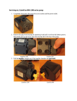
3. When the pump is upright, the oil has to be pumped out of the
oil chamber. Use a suction pump with a flexible suction hose
that can be inserted deeply into the oil chamber.
4. Pump out the oil using all the screw holes in turns so as to
reach all sections of the interior of the oil chamber. Collect the
drained oil in a clean container.
5. Replace the O-rings, refit screw C and tighten securely. Fill
the oil chamber with oil to the correct level. Refit screws A and
B and tighten securely.
Lack of oil may cause overheating and damage of
the mechanical seals. The WIO sensor in the oil
chamber will trip the alarm if the oil quality is poor or
there is no oil in the oil chamber.
TM03 1628 2705
CAUTION
Pressurised system
Minor or moderate personal injury
- When loosening the screw of the oil chamber, note
that pressure may have built up in the chamber. Do
not remove the screw until the pressure has been
fully relieved.
Used oil must be disposed of in accordance with
local regulations.
TM02 4005 4601
A
B

English (GB)
13
8.6 Inspection and adjustment of impeller clearance
The correct axial clearance is 0.7 mm ± 0.2. Reset the clearance
if it is 0.7 mm or more. The method for resetting the clearance is
different for submersible pumps, installation types S, C and ST,
and for dry-installed pumps, installation types D and H. For dry-
installed pumps there are two methods.
All methods are described here.
8.6.1 Submersible pumps, installation types S, C and ST
Submersible pumps have a separate, adjustable pump inlet cover
which may be shaped as an inlet bell. When the pump is installed
or pulled out of the pit for service, locate the six fastening screws
of the inlet cover and the three set screws.
Use a feeler gauge to check the clearance between the impeller
and the inlet cover all around the perimeter of the inlet opening.
See fig. 10.
Fig. 10 Impeller clearance adjustment
8.6.2 Dry-installed pumps, Installation types D and H
Proceed as follows:
1. Loose the six fastening screws and close the impeller
clearance by tightening the three set screws. Tighten the
screws diagonally to move the inlet cover evenly.
2. Measure the distance "L" between inlet cover and pump
housing at three points next to the set screws, using feeler
gauges or callipers, and make a note of the distance.
3. Loosen the set screws and draw back the inlet cover by
between 0.5 and 0.9 mm using the six fastening screws
(approx. one 270 ° turn of an M12 fastening screw) and the
distance "L" as reference. See fig. 11.
4. Tighten all set screws and check that the distance "L" at the
three reference points is stable at the new value.
Fig. 11 Impeller clearance adjustment
8.7 Electrical measurements
In case the cable is damaged, measure from the cable terminal
with the cable disconnected.
Connections in terminal boards are accessible by hand once the
motor has been removed. See section 9. Dismantling and
assembly instructions.
8.7.1 Checking the internal motor control devices
1. Connect tester (test bell, test lamp, etc.) to leads P1 and P2 (1
and 2).
2. If tester functions (bell rings, lights come on) the control circuit
is closed and intact.
8.7.2 Checking the earth connection
1. Connect one tester to the earth lead (yellow-green wire).
2. Connect second tester to the pump body.
3. In case the tester functions, the earth connector is in order.
In case the tester doesn’t function, the earth connector is
faulty and must be repaired.
It is not possible to adjust the clearance of SV
pumps.
You can check the impeller and pump housing for
wear only.
TM05 1916 3911
Do not use too much force when tightening the
fastening screws as this may damage the bearings.
The movement is usual 1 to 3 mm.
Set screw
0.7
Fastening screw
Fastening screw
TM05 1915 3911
DANGER
Electric shock
Death or serious personal injury
- The pump must not be connected to the mains if
the earth connections is not intact.
Do not connect the tester to the cooling jacket, if any.
Set screw
0.5 - 0.9
Fastening screw
Fastening screw
L

English (GB)
14
8.7.3 Checking the insulation resistance
Insulation resistance can be measured from the cable end
(control cabinet) or from the stator wires. Use a tester that can
apply at least 500 VDC.
1. Measure the insulation resistance. As a minimum there must
be 100 MΩ between:
– earth (body) to phases U, V and W
– earth (body) to control circuit leads P1 and P2 (1 and 2)
– control circuit leads P1 and P2 to phases U, V and W
– between phases.
2. If any of the above-mentioned measurements are below 100
MΩ, measure cable, windings and devices separately to find
out where the insulation resistance has decreased.
Reduction of insulation resistance due to moisture requires
drying of the relevant parts, see sections 8.7.5 Drying of the
cable and 8.7.6 Drying of the stator and the rotor.
3. Check that the conductor markings are indicated at the end of
the cables.
8.7.4 Checking the stator winding resistance
The measurements can be performed with a reliable multimeter
that is capable of measuring Ω-values with 3 digit accuracy.
The maximum allowed difference between phases is ± 10 %.
Proceed as follows:
1. Disconnect the stator winding wire ends from the terminal
board.
2. Identify the wire markings and proceed according to step 3 or
step 4.
Step 3 applies only for the wires marked with the letters U, V and
W.
3. Measure the stator winding resistance between:
– U1 and U2
– V1 and V2
– W1 and W2.
Step 4 applies only for the wires marked with the letter T.
4. Measure the stator winding resistance between:
– T1 and T4
– T2 and T5
– T3 and T6
– T7 and T8 (2 phases in series)
– T8 and T9 (2 phases in series)
– T9 and T7 (2 phases in series).
5. Compare the measured values to the values in the winding
resistance value table. See section 11.4.1 Cable and winding
resistances. In case of 2 phases in series, the measured
values need to be divided by 2 before comparing them to the
values in the tables.
If no or only very few readings are obtained, the stator must
be dried before the measurements are carried out again. See
section 8.7.6 Drying of the stator and the rotor.
Consistent false reading of the stator winding resistance
values is sufficient evidence of a winding damage. In case the
stator needs to be replaced, see section 9. Dismantling and
assembly instructions.
8.7.5 Drying of the cable
1. See section 9.3.5 Removing the motor top cover.
2. See section 9.1 Checking and replacing the cable.
3. Blow clean air (max. 0.8 bar) through the cable.
4. Dry for approx. 20 hours.
5. Connect the old cable or replace it with a new one.
6. Measure the resistance. See section 8.7.3 Checking the
insulation resistance.
8.7.6 Drying of the stator and the rotor
1. See section 9. Dismantling and assembly instructions.
2. Place the stator and rotor in an oven at 100-110 °C.
3. Dry for 6 to 12 hours.
4. Let the stator and rotor cool down.
5. Measure the winding resistance.
If the measurements are not valid, replace the stator. See
section 9.3.12 Removing the stator.
6. See section 9. Dismantling and assembly instructions.
Always disconnect the stator winding wires from the
terminal board before measuring resistance values
from them.
Make sure that the cables are disconnected from the
terminal board before removing the cable entry.
If the stator is wet, not only the stator but also the
rotor must be dried. If this is not done, the stator may
become moist again after re-assembly and trip the
moisture switch.

English (GB)
15
9. Dismantling and assembly instructions
Position numbers of parts (digits) refer to section 11. Drawings
and section and position numbers of tools (letters) refer to section
7. Service tools.
9.1 Checking and replacing the cable
Make sure that the cables are not sharply bent or pinched and
that the cable sheath has no visual defects.
9.1.1 Cable change
Disconnect the cable - composite cable entry (non-Ex)
Fig. 12 Cable entry attached to motor top cover
1. See section 9.3.4 Removing the cooling jacket.
2. See section 9.3.5 Removing the motor top cover.
3. Remove the screws (181a). See fig. 12.
4. Pull the cable (181) including the cable entry assembly out of
the motor top cover (164a).
5. Remove the cable entry (168) including the rubber seal (198)
and cable clamp (180), if any, from the cable (181).
6. Remove the rubber seal (198) from the cable entry (168).
7. Remove the cable clamp (180) from the cable entry (168).
Connecting the new cable - composite cable entry (non-Ex)
1. Slide cable entry (168) on the cable (181).
2. Slide the cable clamp (180) and rubber seal (198) on the
cable (181).
3. Fit the cable clamp (180) and rubber seal (198) on the cable
entry (168).
4. Fit the cable entry to the motor top cover (164) with screws
(181a).
5. Tighten the screws (181a) evenly with a torque. See section
6. Torques and lubricants.
Disconnect the cable - metal cable entry (non-Ex/Ex)
This section is only valid for range 70 pumps.
Fig. 13 Cable entry attached to motor top cover
1. See section 9.3.4 Removing the cooling jacket.
2. See section 9.3.5 Removing the motor top cover.
3. Remove the screws (180a). See fig. 13.
4. Remove the cable clamp (180).
5. Remove the screws (181a).
6. Pull the cable out of the motor top cover (164a).
7. Remove the cable entry (168) including the rubber seal (198)
and washer (185), if any, from the cable (181).
8. Remove the rubber seal (198) from the cable entry (168).
There are several service videos available as
guidance on Grundfos Product Center or YouTube.
Always use original service parts from the
manufacturer.
Do not disassemble the cable entry unless you are
going to replace it.
Disconnecting the cables will shorten them
significantly.
TM06 7485 3516
Make sure that the cables are disconnected from the
terminal board before removing the cable entry.
181a
181
198
164
168
180
To prepare a new cable (length of leads, cable clips,
cable markings, etc.), please use the old cable as
reference.
Connect according to the wiring diagrams.
TM06 7216 3016
Make sure the cables are disconnect from the
terminal board before removing the cable entry.
181
168
180
180a
198
164a
181a
185

English (GB)
16
Connecting the new cable - metal cable entry (non-Ex/Ex)
1. Measure (K) the outer diameter of the cable (181) and the
hole diameter (cable ID) from the motor top cover (164a).
Check the number of washers (185) needed, if any, in the
table below.
2. Slide cable entry (168) on the cable (181).
3. Fit the cable entry (168), washer(s) (185) and rubber seal
(198) on the cable (181).
4. Fit the cable entry to the motor top cover (164a) with screws
(181a).
5. Tighten the screws (181a) evenly to the torque specified in the
table above.
6. Fit the cable clamp (180a) to the cable entry (168) with screws
(180a).
9.2 Replacing the protection sensors
9.2.1 Moisture switch
The standard pumps have one moisture switch under the motor
top cover. The Ex pumps have two moisture switches, one under
the motor top cover and one in the stator housing. On Ex pumps
manufactured before February 2009, both moisture switches are
placed under the motor top cover
The changing method is the same, no matter where the switch is
placed.
Checking the moisture switch
1. Connect the switch to a simple bell circuit or another test
circuit.
2. Adjust the clearance between expander part and the switch
body to 2.5 mm by using the adjustment gauge
3. Remove the adjustment gauge.
Checking the microswitch
1. Connect the test bell or other test circuit.
2. Place the adjustment gauge between the expander part and
the switch body.
3. Pull the expander outward two to three times to make sure the
that the bell stops ringing (the electric circuit will be broken)
when the expander is pulled outward and starts to ring when
the expander is free.
Adjusting the clearance of the moisture switch
1. Place the adjustment gauge between the expander part and
the switch body.
2. Pull the expander outward:
– If the bell rings, turn the adjusting screw clockwise until the
bell stops ringing
– If the bell is not ringing, turn the adjusting screw
counterclockwise until the bell starts ringing.
3. Remove the adjustment gauge
Install the switch and test the microswitch.
Fig. 14 Moisture switch
To prepare a new cable (length of leads, cable clips,
cable markings, etc.), please use the old cable as
reference.
Cable ID
[mm-ver.]
Cable [mm]
Washer
[pcs.]
Torque
[Nm]
min. max.
36-1
14.4 15.4 -
10
15.4 16.4 1
36-2
17.2 17.5 0
17.5 18.8 1
18.8 20.0 3
46-1 15.7 17.2 -
45
46-2
17.8 18.5 -
18.5 19.2 1
19.2 20.0 2
46-3
20.9 21.5 -
21.5 22.4 1
22.4 23.4 3
46-4
23.8 24.6 -
24.6 26.0 2
26.0 27.0 5
65-1 28.3 31.4 -
65-2
32.5 33.6 2
33.6 34.7 3
If a gap remains between the motor top cover and
cable gland/washer wait for 30-60 minutes and
retighten the screws.
Connect according to the wiring diagrams.
Do not touch the head of the moisture switch with wet
or oily hands. Moisture on the sensor head before
installation will cause false measuring values.
TM06 7199 3016
Spade connectors
Mounting screw
and lock washer
Mounting bracket
Screw

English (GB)
17
Removing the moisture switch
1. Disconnect the spade connectors from the switch.
2. Remove the mounting screw and lock washer from the
mounting bracket. Remove the switch.
3. Remove the screw.
4. Remove the switch from the mounting bracket.
Fitting a new moisture switch
5. Fit the moisture switch to the mounting bracket.
6. Fit the screw to attach the switch to the mounting bracket.
7. Fit the mounting bracket including the switch on the base with
the mounting screw and the lock washer.
8. Connect the spade connectors.
9. Connect the wires according to the wiring diagram. See
section 11.4 Electrical connections.
9.2.2 Pt100 sensor on lower bearing bracket
Fig. 15 Pt100 sensor in lower bearing bracket
Removing Pt100
1. Cut the wire of the Pt100 sensor right next to sensor. Remove
the wire.
2. Drill out the sensor from the lower bearing bracket (155).
Fitting new Pt100
3. Dip the sensor head in glue and insert it in the hole in the
lower bearing bracket (61).
4. Connect according to the wiring diagram. See section
11.4 Electrical connections.
9.2.3 Pt100 sensor on the stator
Removing Pt100
1. Cut the wire of the Pt100 sensor right next to the sensor and
remove the wire.
2. Leave the old sensor on the stator.
Fitting new Pt100
3. Glue the sensor onto the stator windings (48).
4. Connect according to the wiring diagram. See section
11.4 Electrical connections.
9.2.4 Water-In-Oil sensor (WIO)
Fig. 16 External Water-In-Oil sensor (WIO)
Removing the WIO sensor
1. Place the pump on vertical position.
2. Loosen the WIO inlet and remove the sensor.
3. Replace immediately with new sensor or the oil plug (193) and
the O-ring (194).
Fitting new WIO sensor
Fig. 17 Installation of WIO sensor
1. Fit the WIO sensor in the hole of oil plug B. See figs 8 and 9
for correct position. Make sure that the sensor head is inside
the oil chamber. See installation length above.
2. Connect according to the wiring diagram. See section
11.4 Electrical connections.
TM06 7556 3616
Make sure that the wire of new sensor is protected by
a protection sleeve.
Pt100
TM06 7248 3116
We recommend to change the motor oil in case the
WIO sensor is changed.
TM03 5531 0617
Range Installation length [L]
66 and 70 100 mm
L

English (GB)
18
9.3 Dismantling - S pump
For position numbers, see section 11. Drawings.
9.3.1 Removing the pump housing and impeller
1. Place the pump in vertical position and support it by means of
a hoist fastened to the lifting bracket (190).
2. Remove the screws (26c) in the pump housing (50).
3. Lift the motor including the impeller (49) out of the pump
housing (50).
If necessary, tap all around the housing with a soft hammer to
remove the motor or pry it loose with a pry bar.
4. Place the motor in horizontal position on a firm workbench or
trestle with the impeller facing outward.
5. Support the impeller by means of lifting belt.
6. Loosen the impeller screw (67).
7. Loosen the impeller (49), use pinch bars if needed.
8. Remove the impeller screw (67), O-ring (67b) and the impeller
cap (66).
For some non-SuperVortex pumps it is necessary to use an
impact puller (M) to remove the impeller cap (66).
9. Remove the impeller (49).
9.3.2 Draining the oil
1. See section 8.5 Oil check and oil change.
9.3.3 Removing the primary shaft seal
1. See section 9.3.1 Removing the pump housing and impeller.
2. See section 9.4.3 Draining the oil.
3. Remove the key (9a). Tap gently with plastic hammer if
needed.
4. Loosen the set screws in the shaft seal (105) and remove the
rotating part.
5. Gently remove the stationary ring of the shaft seal (105).
9.3.4 Removing the cooling jacket
1. Remove connections of external WIO sensor cables, if any.
2. Remove the screws (190b) and lifting bracket (190).
Tap gently with plastic hammer bottom of the cooling jacket to
loose the fitting, if needed.
3. Pull out the cooling jacket (150c) from the brackets with a
hoist.
4. Remove O-rings (37a and 157b)
9.3.5 Removing the motor top cover
1. See section 9.3.4 Removing the cooling jacket.
2. Remove the screws (178).
3. Lift the motor top cover (164a) approx. 10 cm. Tap lightly, if
needed.
4. Disconnect the cables.
5. Remove the motor top cover (164a).
6. Remove the O-ring (157).
7. Make sure the pin (59b) stay’s in the groove of upper bearing
bracket (61c).
9.3.6 Removing the shaft seal housing
1. See section 9.3.1 Removing the pump housing and impeller.
2. Loosen the screws (26a).
3. Loosen the seal house cover (77). Use pinch bars to loosen
the fitting.
4. Remove the screws (26a) and the seal house cover (77)
including O-ring (107).
5. Remove the screws (184).
6. Remove the seal housing (58) including O-ring (72). Tap
gently with plastic shammer if needed.
7. Remove the O-rings (72 and 72a).
9.3.7 Removing the secondary shaft seal
1. See section 9.3.6 Removing the shaft seal housing.
2. Loosen the set screws in the secondary shaft seal (105b).
3. Remove the rotating and stationary parts of the shaft seal
(105b) from the shaft. Use pinch bars if needed.
9.3.8 Removing the upper bearing bracket
1. Disconnect the sensor cables from the terminal block (176c).
2. Remove the moisture absorbing bag.
3. Remove the pin (59b).
4. Place screw in the screw hole in the upper bearing bracket
(61c). Use M10 for both ranges.
5. Turn the screw in the hole so that the upper bearing bracket
(61c) starts to pull up.
6. Remove the upper bearing bracket (61c).
9.3.9 Removing the upper bearing
1. See section 9.3.10 Removing the rotor.
2. Pull out the bearing (154) from the shaft by using a bearing
puller, if needed.
9.3.10 Removing the rotor
1. See section 9.3.7 Removing the secondary shaft seal.
2. Place the motor in vertical position so that the shaft end is
pointing upwards.
3. Insert an eyebolt in the shaft end.
4. Lift the rotor assembly off the stator housing (55) using a
hoist.
If the fitting is tight, loosen it using pinch bars.
5. Place the rotor assembly in horizontal position.
6. Remove the eyebolt and protect the shaft end from dirt.
Maintenance and service work on explosion-proof
pumps must be carried out by Grundfos or a service
workshop authorised by Grundfos.
Handle seal parts with extreme care to prevent
damage. Be very careful not to damage the
precision-finished seal faces; even fingerprints can
shorten the seals life.
CAUTION
Sharp element
Minor or moderate personal injury
- Cover the sharp edges of the keyway on the shaft,
for instance with tape.
We recommend drawing a marking on the stator
housing (55) and lower bearing bracket (155) so that
you are able to position the lower bearing bracket
correctly at the assembly.

English (GB)
19
9.3.11 Removing the lower bearings
1. See section 9.3.10 Removing the rotor.
2. Remove the screws (182b).
3. Lower the bearing bracket cover (60) so that it is lying against
the stator.
4. Remove the lower bearing bracket (155) by using a puller.
5. Remove the circlip (188) and the locking ring (197).
6. Remove the ball bearing(s) (153) by using a bearing puller.
7. Remove the circlip (187) and the washer (187a).
8. Remove the bearing bracket cover (60).
9.3.12 Removing the stator
If the stator package is reused the support ring must be placed
below the stator package to avoid break down.
Fig. 18 Removing stator
1. Lift the stator slightly off the floor.
2. Heat the stator housing (55) at the same time with 2 or 3 gas
burners beginning from the bottom edge. See fig. 18.
3. Carry out the heating as quickly as possible. The stator
package (48) will drop to the floor when enough heat has
been applied.
9.4 Dismantling - ST pump
9.4.1 Removing the outlet bowl
1. Secure the pump on vertical from the lifting bracket (190)
position by means of hoist.
2. Remove screws (26) and seat ring (1).
3. Lift carefully the motor (301) together with the impeller (49)
from the outlet bowl (50).
9.4.2 Removing the impeller
1. Place the motor assembly in horizontal position on a firm
workbench or trestle with the impeller facing outward.
2. Support the impeller by means of lifting belt.
3. Loosen the impeller screw (67).
4. Loosen the impeller (49), use pinch bars if needed.
5. Remove the impeller screw (67) including the O-ring (67b)
and the impeller cap (66) including the O-ring 862a).
6. Remove the impeller (49).
7. Remove key (9a).
9.4.3 Draining the oil
See section 9.3.2 Draining the oil.
9.4.4 Removing the primary shaft seal
See section 9.3.3 Removing the primary shaft seal.
9.4.5 Removing the cooling jacket
See section 9.3.4 Removing the cooling jacket.
9.4.6 Removing the motor top cover
See section 9.3.5 Removing the motor top cover.
9.4.7 Removing the shaft seal housing
See section 9.3.6 Removing the shaft seal housing.
9.4.8 Removing the secondary shaft seal
See section 9.3.7 Removing the secondary shaft seal.
9.4.9 Removing the upper bearing bracket
See section 9.3.8 Removing the upper bearing bracket.
9.4.10 Removing the upper bearings
See section 9.3.9 Removing the upper bearing.
9.4.11 Removing the rotor
See section 9.3.10 Removing the rotor.
9.4.12 Removing the lower bearing
See section 9.3.11 Removing the lower bearings.
9.4.13 Removing the stator
See section 9.3.12 Removing the stator.
TM06 7906 4716
Make sure you use suitable protection equipment.

English (GB)
20
9.5 Assembling - S pump
The torques for the screws and the lubricants for the O-rings are
specified in section 6. Torques and lubricants.
9.5.1 Fitting the stator
Fig. 19 Fitting the stator
1. Place the stator package (48) in the assembly ring. Make sure
that the stand is high enough (dimension H).
2. Heat the stator housing (55) to 200-250 °C with gas burners or
in a oven.
3. Lift the heated stator housing (55) over the stator (48) and
lower it carefully onto the stator (48). Make sure the position is
correct.
4. Check the assembly dimension A.
9.5.2 Fitting the rotor
1. Fit and lubricate the O-rings (72 and 72a).
2. Fit the eye bolt in the shaft end and lift the rotor assembly into
the stator housing (55) using a hoist.
Make sure to position the rotor assembly in accordance with
the marking made during dismantling so that the oil holes of
the oil cover are positioned directly above the oil holes of the
seal housing.
3. Carefully tap on the lower bearing bracket (155) into the stator
housing (55).
9.5.3 Fitting the upper bearing
1. Place the shaft (172) in vertical position so that the shaft end
is pointing downwards.
2. Heat up the ball bearing (154) to 110 °C and fit it on the shaft.
3. Let the assembly cool down.
4. Grease the ball bearing (154). Fill only 50 % of the free space
of the bearing.
9.5.4 Fitting the upper bearing bracket
1. Pull the stator cables through from the cable holes.
2. Fit the upper bearing bracket (61) to the stator housing (55).
If needed, tap gently.
3. Fit the pin (59b).
4. Connect according to the wiring diagram. See section
11.4 Electrical connections.
9.5.5 Fitting the lower bearing
1. Place the shaft in vertical position with the shaft end pointing
upwards.
2. Fill the bearing bracket cover (60) with grease and place the
cover on the shaft so that it is lying against the rotor.
3. Place the washer (187a) and the circlip (187) on the shaft.
4. Heat up the ball bearing to 110 °C and fit it on the shaft.
5. Let the assembly cool down.
6. Grease the ball bearing (153). Fill only 50 % of the free space
of the bearing.
7. Heat up the lower bearing bracket (155) to 110 °C and press it
home.
8. Fit the bearing bracket cover (60) and screws (182b) to the
lower bearing bracket cover (155).
TM06 7907 4216
Range
Lamination
length
L [mm]
Assembly
ring height
H [mm]
Stator
wires
Assembly
dimension
A [mm]
66
210 min. 215
Up
210
250 min. 175 170
255 min. 170 165
280 min. 145 140
70
400 min. 250 245
450 min. 200 195
260 min. 235 230
300 min. 195 190
340 min. 155 150
A
L
H
Only press on the inner ring of the bearing.
/