Page is loading ...

Electrical connection
The fan motor must always be controlled by a frequen-
cy converter, which permits the possibility of regula-
tion and soft starting.
N.B. The fan must not be started directly.
From the rating plate, determine the MAXIMUM
frequency to which the fan motor may be regulated.
Under no circumstances must the fan motor be
supplied at a higher frequency.
Electrical connection must be performed by a quali-
fied electrician.
The cable between the terminal box of the motor and
the frequency changer must be screened. A safety cut-
out switch must be installed between the electricity
mains supply and the frequency changer.
The safety cut-out switch is fitted close to the fan
inspection door.
Before working on the fan, the fan must be switched
off with the safety cut-out switch.
Fläkt Woods 8201 GB 2012.11 1 Specifications are subject to alteration without notice
EU Air Handling Unit INSTALLATION
Installation alternatives
Connection of outlet duct
Connection of the duct to the outlet from the fan unit
must take place in accordance with one of the examples
in Fig. 2.
Important!
The unit must not be allowed to support the weight of
the duct.
The duct may be connected in accordance with the
following alternatives:
A. Via a transition piece fixed to the casing with self-
tapping screws. The duct connection is then made
with a PG joint or a flanged union. Fig. 2a.
B. Via a flexible sleeve coupling fixed to the casing with
self-tapping screws. The duct connection is then
made with a PG joint or a flanged union. Fig. 2b.
C. Via a direct edge-mounted duct provided with sheet
metal angles at the corners. Fig. 2c.
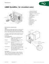
Fan EULK
Fig. 1
Protective net
EULZ-35
Counterflange
EULZ-34
Flexible sleeve
coupling EULZ-32
Transition piece
EULZ-33
Connection
accessories for
outlet:
Internal contact protec-
tion, outlet EULZ-36
Internal contact
protection,
inlet EULZ-37
Protective net for
door EULZ-38
Fig. 2a Fig. 2b Fig. 2c
EUL(B,F) 4A
EUL(B,F) 4B
EUL(B,F) 4C
Transition piece Flexible sleeve Counterflange Duct
EULZ-33 coupling EULZ-34
EULZ-32
xxx xxxx xxxxxx xxx
xxxx xxxxxxxx xx
xxx xxxx xxxxx
MAX frequency
Fig. 3

Electrical connection, continued.
Drill a hole for the cable conduit entry into the unit
casing at a suitable point in the fixed panel. Fig. 4 and
Fig. 5.
The cable must not be routed through the inspection
door. The screwed fitting for the cable can be executed
as shown in Fig. 6.
EULK can be supplied with an external, factory-
installed frequency converter connected to the termi-
nal box of the motor with a screened cable; accessory
STRZ-54. A safety isolator with cabling to the frequen-
cy converter is also available as an accessory; STRZ-65.
NOTE. STRZ-65 can only be ordered as a complete
assembly with STRZ-54.
EULK can also be supplied with a factory-installed
screened cable for an external screened terminal box;
accessory STRZ-66.
Fan EULK
Fläkt Woods 8201 GB 2012.11 2 Specifications are subject to alteration without notice
EU Air Handling Unit INSTALLATION
EUL(B,F) 6
EUL(B,F) 7
Fig. 5 Fig. 6
Testing before commissioning
– Check for compliance with the EU Machinery
Directive in respect of contact protection. Wherever
the fan unit is accessible from a duct or other func-
tional component, the fan unit must be fitted with
contact protection EULZ-36 and/or EULZ-37. Door
protective net EULZ-38 can be used as contact protec-
tion for the fan unit inspection door. See Fig. 1.
– Check that a qualified electrician has issued an
approval certificate prior to commissioning.
– Check that the impeller wheel rotates freely and that
no foreign objects are present which may be sucked in
and cause damage to the fan.
– If the fan is fitted with spring isolators, the transport
brackets must be removed before starting.
Airflow measurement
= Fixed panel
Fig. 4
Important!
If the fans are not operated for more than 3 months
before or after installation, the fans must be rotated
by hand at regular intervals. If not, the ball bearing
may suffer the following damage; see the illustration.
Belastningsskador
Load-induced damage

EULK is available with equipment for air flow meas-
urement, “d” = 1 or 3 in the EULK code. The air flow, q,
can be calculated from the following formula using a
measurement pressure of Δp(Pa), and a constant k:
The measurement pressure, Δp, which is the differ-
ence between the pressure in the empty part of the
fan inlet and the pressure inside the inlet cone, can be
read with a manometer (pressure range up to 6000 Pa)
connected to 2 externally located nipples. The value of
the constant k is shown in the table below.
A flow indicator with a built-in pressure transducer,
STYZ-78, is available as an accessory. STYZ-78, which
is connected via hoses to the external nipples, converts
the measurement pressure into a flow (m3/s) which
is indicated on a display and gives an output signal of
0-10 V in a linear relationship with the flow.
(See instruction for STYZ-78).
Fan EULK
Fläkt Woods 8201 GB 2012.11 3 Specifications are subject to alteration without notice
EU Air Handling Unit INSTALLATION
Size EULK, aa-b k- factor
20-2 42,55 1 fan
20-3 37,34 1 fan
21-2 29,95 1 fan
21-3, 22-2, 30-2 22,73 1 fan
30-3, 31-1 18,77 1 fan
31-2, 32-1 15,34 1 fan
31-3, 32-2, 33-2, 40-2 12,18 1 fan
40-3, 41-2, 42-1 9,49 1 fan
41-3, 42-2, 44-2, 51-1 7,5 1 fan
44-3, 50-3,51-2, 52-1, 60-1, 62-1 6,02 1 fan
51-3, 52-2, 53-2, 60-2, 62-2 4,6 1 fan
52-3, 53-3, 60-3, 64-1, 71-1, 73-1, 80-1 3,8 1 fan
62-3, 64-2, 71-2, 73-2, 80-2, 82-1 3,75 2 fans
64-3, 73-3, 82-2, 84-1 3,01 2 fans
64-4, 73-4, 82-3, 84-2 2,3 2 fans
84-3 1,9 2 fans
Where the fan section includes two fans the k-factor is valid for
the total air flow rate.
+–
�p
Fig. 7
q = √ Δp (m3/s)
1
kx
Temperature correction
The flow scale on the display instrument and the above
flow formula are applicable to air at a temperature of
+20°C. At other air temperatures, the flow must be
corrected using the formula:
where q = the actual flow through the fan, q20 = the
flow value reading and t = the prevailing temperature
in °C.
q = q20
(273 + t)
293 , m3/s
√

Frequency converter
Connection of the screening conductor shall be
made via an EMC approved union in the frequency
converter’s casing or by using a clamp intended for this
purpose. The screen conductor must not be connected
to an earth bolt.
Connection of the screen conductor
In those cases the screen conductor must be connected
to an earth bolt in the motor or frequency converter,
this should be done so that the impedance is as low
as possible, in these cases, this conductor is limited
in length to 5 times its width. For example, when the
screen conductor is 1 cm wide it must not be longer
than 5 cm.
Diverse
Besides this, the following should be observed:
– type of mains supply.
– local regulations and provisions.
– the manufacturer’s installation instructions for the
frequency converter.
Outputs over 22 kW
In the event of outputs over 22 kW, a symmetrical
screened cable with concentric or in some other way
symmetrically designed protective earth conductor
should be used, please refer to the installation instruc-
tions for the frequency converter for recommendations
concerning these installations.
Fan EULK
Fläkt Woods 8201 GB 2012.11 4 Specifications are subject to alteration without notice
EU Air Handling Unit INSTALLATION
Installation of the frequency converter
Warning: Incorrect installation of the frequency
converter can damage the bearings in the motor.
It is Fläkt Woods’ policy to only except claims
when the motor and frequency converter have been
supplied and installed by us.
Damage to the motor will not be accepted when the
motor has been connected to the frequency convert-
er by an installation engineer not provided by Fläkt
Woods.
The frequency converter and the motor must be
installed by a qualified electrician with good knowl-
edge of speed regulated, drive system installations
(frequency converters) and EMC-safety.
The following recommendations should be seen
as a supplement to the manufacturer’s installation
instructions. In those cases where there are differenc-
es, the manufacturer’s instructions shall take prec-
edence over the following; this is due to the warranty
undertaking from the manufacturer.
General
The installation between the motor and the
frequency converter should be carried out using
screened, unbroken 4-wire cable intended for
EMC-installations for motor operations, the screen
shall have at least 80% optical density, for example,
Nexan’s NCY or Ölflex Classic. The screen shall have
360° contact with the casing both in the motor and in
the frequency converter to give the maximum contact
surface. Safety switches or connection boxes fitted
between the frequency converter and motor are not
recommended.
Motor
The cable gland in the motor’s outlet box should
consist of an EMC approved cable gland, for exam-
ple, Miltronic SKINTOP MS-SC. The screen conduc-
tor may only be connected via EMC unions, not to
earth bolts.
The screen
should have
360° contact
with the casing
Screen Insulating tape
Insulating tape
The screen
should have
360° contact
with the
casing
Screen
Casing
Fig. 8
Fig. 9
Fig. 10
/