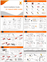
Part 3 Installation of Parallel System Part 4 LCD Operation
Part 2 Installation of Parallel BOX
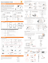
GRID Connection 2.7 Communication Connection
Connection of Parallel Box side
Connection of Inverter side (please refer to Inverter User Manual for details )
Make communication cables
If the user is used with X3--Hybrid/Fit G2 inverter, please connect as follows:
Remove 4mm insulation from cable ends.
Insert the cable into the green terminal in the accessory bag, then use a screwdriver to tighten the cable and insert it into the corresponding
port.
Crimp!
green terminal
Disconnect the insulation layer of the
communication cable, and then insert one
side of the cable corresponding to the
GND and EPS port into the pin5 and pin6 holes
of the 8-pin positive terminal in the accessory bag.
Prepare a connector and two communication cables.
Unscrew the nut of connector on the bottom of the inverter and
insert two communication cables through it.
10.0mm
conductor
communication cable
8pin terminal
(in accessories package)
Insert the cables
Screw the wires
Insert the positive terminal into the corresponding
negative terminal block inside of the inverter. And
then screw it tightly.
Screw the terminal
RS485-Meter connection:
Insert one side of CAT5 cable into the RS485 port of meter, and the other side into the
CAN 1 port of the first inverter or the CAN 2 port of the last inverter.
Please note the inverter connected with meter will be the Master Inverter and this
Master inverter must be connected with battery.
Note: For specific cable operation of these cables, please refer to Inverter User Manual.
Insert one side of CAT7 cable into the first inverter’s CAN port and the other side into the next inverter’s CAN port.
CAN-CAN connnection: There are three work modes in parallel system, and your acknowledge of different inverter’s work modes will help you understand parallel
system better, therefore please read it carefully before operating.
Find the inverter connected with the SolaX meter, then enter the setting page of the inverter LCD screen, click on the parallel settings,
and select "master control"; then enter the "resistance switch"and set it to " ON"; Finally, find the last slave in the parallel system and
enter the setting page of the inverter LCD screen and set the "resistance switch" to "ON".
Notes: Once this inverter is set as a “Master”,all other inverters will enter “slave mode” automatically.
Main display:
Once inverter enters parallel system, the “today yield” will be replaced by “ Inveter Class”, and parallel relevant fault has a higher priority than other
faults and will be showed firstly on main display.
Power
Today
Battery
Normal
5688W
20.5KWh
67%
Power
Parallel
Battery
Normal
5688W
Master
67%
Power
Parallel
Battery
Normal
5688W
Slave1
67%
Free mode
Master mode
Slave mode
Only if no one inverter is set as a “Master”, all inverters are in free mode in the system.
When one inverter is set as a “Master”, this inverter enters master mode.
Master mode can be changed to free mode.
Once one inverter is set as a “Master”, all other inverters will enter slave mode
automatically. slave mode can not be changed from other modes by LCD setting.
Status
Menu
>Parallel Status
History
>All
Parallel Status
Slave1
Slave2
2
>Grid
Parallel Status
Solar
Load
Means the total number of online inverters.
Status display:
User can obtain all the status data from master inverter. System power and individual slave inverter power can be obtain in status
display of master inverter.
“Master Inverter” setting in LCD display
- If one inverter want to exit from this parallel system, please do the steps as below:
step 1: Disconnect all the network cables on the CAN port.
step 2: Disconnect all power cables (R/S/T/N/PE) connected to X3-Parallel Box.
step 3: Enter setting page and click parallel setting, and choose “Free”.
Meter Port: The first RJ45 port from left side
CAN CAN
CAN Port: The first RJ45 port from left side
CAT5 cable
CAT7 network cablesCAT7 network cables
CAN-CAN CAN-CAN CAN-meter
Meter
CAN1 CAN2 CAN1 CAN2 CAN1 CAN2
BBBA
EPS cable
GND cable
2.5
614.00659.01
Torque:0.2±0.1 N·m
Torque: 0.2±0.1 N·m
Torque:0.4±0.1 N·m
CAT7 network cables
CAN-CAN
Meter(RS485)-Meter
Master Inverter Terminal Inverter
... ...
CAN2CAN1
X3-Parallel Box Meter
A
BB
CAT5 network cables
A
1 2 3456 7 8
1) White with orange stripes
2) Orange
3) White with green stripes
4) Blue
5) White with blue stripes
6) Green
7) White with brown stripes
8) Brown
Multifunction terminal
crimping tool (RJ45)
15.00mm
Diagonal pliers
GND
EPS
EPS cable
GND cable
If the user is used with X3--HybridG4 inverter, please connect as follows:
Use a common network cable and Remove 4mm insulation from cable ends.
Insert the cable into the RJ45 terminal in the accessory kit, then use a diagonal pliers to tighten the cable and insert it into the
corresponding port.
Battery
Setting
Parallel Setting
Reset
Status
Parallel Setting
>setting Master
Free
>Resistance Switch
Parallel Setting
ON
If the user is used with X3-Hybrid/Fit G2 inverter, please connect as follows:
If the user is used with X3--Hybrid G4 inverter, please connect as follows:
CA N CA N DRM S HU T
CAN CAN DRM SHUT
CA N CA N DR M SH UT
* Note: It is best to connect the CAN port on the left of "Master" to X3-Parallel Box,
and connect the CAN port on the right to "Slave”. Master CAN Slave CAN
2.6 Ground Connection
Step 1: Find a longer ground cable from the attachment.
Step 2: Twist the screw between the ground terminal inside the cabinet
and the ground terminal of the chassis, connect them with a ground cable,
and tighten the screws.
- Finally, install the upper cover of the machine and tighten the screws.
Ground terminal
(length, 250mm)
If the user is used with X3--Hybrid G4 inverter, please connect as follows:
If the user is used with X3--Hybrid/Fit G2 inverter, please connect as follows:
GND EPS
GND
EPS
GND EPS
①
②
①
②
① ②
①
③
④
①
②
Connection of Parallel Box side
Make Grid cables
Remove 18mm insulation from cable ends, then Insert the stripping terminal.
Press the terminal head with the blank holder.
Screw cables
Torque:4.0 N·m
18 mm
Crimp!
G
R
N ST For Australia
G
N
TRS
GRIDGRID
For Other Areas
Screw cables through the GRID port on the bottom of the BOX to corresponding Load ports (R-bar, S-bar, T-bar, N-bar, G-bar)
by screwdriver.
Note: For users in most countries, you need to find a ground cable from the accessories, and short-circuit the N-bar of EPS with PE;
for Australian users, you can find a Natural line(Black) in the accessories to connect the N terminal of the Grid Connect with the
N-bar of EPS. ( refer to picture as below )
①
②
Connection of Grid distribution box side
Grid port connection of grid distribution box side should be analyzed and operated depending on field wiring condition.
Here will not be described into details.
L1 L2 L3
N
NP
P
GRID EPS COM LOAD EPS 1.......n(n=5/10)
I version
RS T
G
L1 L2 L3
P
P
N
GRID LOAD EPS
E version
RS T N
G
②