Page is loading ...

Technical Description of
TANDBERG Gateway
with software version G2
TANDBERG
D13192 Rev. 02

Technical Description of TANDBERG Gateway with software version G2
D13192 Rev. 02 2
Table of contents
1 INTRODUCTION ............................................................................................................................................ 4
2 PRODUCT DESCRIPTION............................................................................................................................ 5
2.1 SOFTWARE...................................................................................................................................................... 5
3 OPERATION AND USER INTERFACE ...................................................................................................... 5
4 TANDBERG GATEWAY INTERFACES & FEATURES........................................................................... 6
4.1 NETWORK INTERFACES AND FEATURES.......................................................................................................... 6
4.1.1 Multiple Calls ........................................................................................................................................... 6
4.1.2 PRI E1/T1 ISDN ....................................................................................................................................... 7
4.1.2.1 ISDN number plan ........................................................................................................................................... 7
4.1.2.2 PRI Trunk Grouping........................................................................................................................................ 7
4.1.2.3 PRI E1/T1 ISDN.............................................................................................................................................. 7
4.1.3 Dial In Services......................................................................................................................................... 9
4.1.3.1 Direct Inwards Dialing (DID).......................................................................................................................... 9
4.1.3.2 Interactive Voice Response (IVR) ................................................................................................................... 9
4.1.3.3 TCS-4 .............................................................................................................................................................. 9
4.1.3.4 Hotline ........................................................................................................................................................... 10
4.1.4 IP Dial Out Services ............................................................................................................................... 10
4.1.4.1 Service Prefixes ............................................................................................................................................. 10
4.1.5 Ethernet / LAN Interface (H.323) ........................................................................................................... 10
4.1.5.1 Quality of Service features (QoS) .................................................................................................................. 10
4.1.5.2 IP adaptive bandwidth management .............................................................................................................. 11
4.1.5.3 Dynamic playout buffering ............................................................................................................................ 12
4.1.5.4 Asymmetrical media capabilities ................................................................................................................... 12
4.1.5.5 Diagnostic tools for IP ................................................................................................................................... 12
4.1.5.6 Latency & Jitter ............................................................................................................................................. 12
4.1.5.7 Layer 4 Ports used in H.323 .......................................................................................................................... 13
4.1.5.8 IP packet sizes ............................................................................................................................................... 13
4.1.5.9 Intelligent Packet Loss Recovery (IPLR)....................................................................................................... 14
4.1.6 LEDs Description ................................................................................................................................... 15
4.1.6.1 Description of PRI Alarms............................................................................................................................. 15
4.1.7 Intelligent Call Management (ICM) ....................................................................................................... 16
4.1.8 TANDBERG Gateway Capacity.............................................................................................................. 17
4.1.8.1 TANDBERG Gateway Capacity – typical scenarios for 4Mb Option ........................................................... 18
4.1.9 Secure Conference (Encryption)............................................................................................................. 18
4.1.10 H.243 Multipoint Transparency......................................................................................................... 19
4.2 AGGREGATION STANDARDS.......................................................................................................................... 20
4.2.1 BONDING............................................................................................................................................... 20
4.2.1.1 ISDN channel set-up...................................................................................................................................... 20
4.2.2 H.221 ...................................................................................................................................................... 20
4.2.3 H0 ........................................................................................................................................................... 20
4.3 RS232 INTERFACE/APPLICATION PROGRAMMABLE INTERFACE (API) ......................................................... 21
4.3.1 API commands........................................................................................................................................ 21
4.4 VIDEO FEATURES ......................................................................................................................................... 22
4.4.1 Optimised Video Compression................................................................................................................ 22
4.4.2 Video Formats ........................................................................................................................................ 22
4.4.3 Asymmetric Video Formats..................................................................................................................... 22
4.4.4 Duo Video ............................................................................................................................................... 23
4.4.5 Custom pictures ...................................................................................................................................... 23
4.5 AUDIO FEATURES ......................................................................................................................................... 24
4.5.1 Custom Sounds........................................................................................................................................ 24

Technical Description of TANDBERG Gateway with software version G2
D13192 Rev. 02 3
4.5.2 Telephony................................................................................................................................................ 24
4.5.3 Audio Compression Algorithms .............................................................................................................. 24
4.6 SYSTEM MANAGEMENT................................................................................................................................25
4.6.1 Ethernet/LAN Interface........................................................................................................................... 25
4.6.2 Platform Requirements ........................................................................................................................... 25
4.6.3 Protocols Supported ............................................................................................................................... 26
4.6.4 System Management Functionality......................................................................................................... 27
4.6.4.1 Remote software upgrades using FTP: .......................................................................................................... 27
4.6.4.2 Management using a standard Web-browser: ................................................................................................ 27
4.6.4.3 Management using a standard Telnet-client: ................................................................................................. 27
4.6.4.4 Management using a terminal connected to the RS232 port:......................................................................... 27
4.6.5 Security ................................................................................................................................................... 27
4.6.5.1 HTTPS, TLS/SSL .......................................................................................................................................... 27
4.6.5.2 Telnet Challenge Service ............................................................................................................................... 28
4.6.5.3 Disable Services............................................................................................................................................. 29
4.6.5.4 Security Alert................................................................................................................................................. 29
4.6.6 Layer 4 ports used by the system ............................................................................................................ 30
5 MISCELLANEOUS FEATURES................................................................................................................. 31
5.1 PHONE BOOK ................................................................................................................................................ 31
5.2 FILE SYSTEM (FTP) ...................................................................................................................................... 31
5.2.1 Picture files ............................................................................................................................................. 31
5.2.2 Sound files............................................................................................................................................... 31
5.2.3 Other files ............................................................................................................................................... 31
6 ENVIRONMENTAL ISSUES ....................................................................................................................... 33
6.1 TANDBERG’S ENVIRONMENTAL POLICY ................................................................................................... 33
6.2 ENVIRONMENTAL CONSIDERATIONS............................................................................................................. 33
7 PRODUCT APPROVALS ............................................................................................................................. 34
7.1 CONNECTION OF TELE-TERMINAL EQUIPMENT............................................................................................. 34
7.2 EMC EMISSION - RADIATED ELECTROMAGNETIC INTERFERENCE ................................................................ 34
7.3 EMC IMMUNITY........................................................................................................................................... 34
7.4 ELECTRICAL SAFETY .................................................................................................................................... 34
7.5 EMC IMMUNITY........................................................................................................................................... 34
7.6 NEBS APPROVAL ......................................................................................................................................... 35
8 PRODUCT RELIABILITY........................................................................................................................... 36
9 TECHNICAL SPECIFICATION OF TANDBERG GATEWAY.............................................................. 37
9.1 MECHANICAL INFORMATION......................................................................................................................... 37
9.2 PACKAGING .................................................................................................................................................. 37
9.3 OPERATING TEMPERATURE AND HUMIDITY ................................................................................................. 38
9.4 STORAGE AND TRANSPORT TEMPERATURE .................................................................................................. 38
9.5 SYSTEM POWER CONSUMPTION.................................................................................................................... 38
10 TECHNICAL SPECIFICATION SHEET ...................................................................................................39

Technical Description of TANDBERG Gateway with software version G2
D13192 Rev. 02 4
1 Introduction
The TANDBERG Gateway is designed to connect up to 8 videoconferencing calls and 8
telephone calls simultaneously between ISDN and IP Networks.
The TANDBERG Gateway supports the ITU-T H.320 standard and a combination of H.221 and
BONDING for communication on up to 30 ISDN B-channels as well as ITU-T H.323 v.4
standard for communication up to 2 Mbps over IP networks.
The TANDBERG Gateway is ‘configurationless’ in the sense that no extensive knowledge is
required for installation and maintenance. All features are included in the TANDBERG
Gateway – thus, there is no additional hardware required to use any of the inbuilt features.
All features of the TANDBERG Gateway are based on standards set by the ITU-T.
The TANDBERG Gateway is best utilised when used together with TANDBERG Management
Suite (TMS) and TANDBERG Scheduler, since they have incorporated features like System
Management and Scheduling (Optional).
Major features supported:
• Up to eight separate video and eight separate telephone calls
• Maximum bandwidth for all calls combined is 7680 kbps
• Flexible ISDN Dial-in Services
• Flexible IP Dial-out Services
• Call Transfer
• IP QoS Features
• H.243 Transparency
• H.264 Video Standard
• Custom video formats (e.g. XGA video resolution)
• Full implementation of Downspeeding
• Secure Conference (AES/DES Encryption)

Technical Description of TANDBERG Gateway with software version G2
D13192 Rev. 02 5
• Dual Stream - supports Duo Video
TF
on ISDN and IP, and People+Content on ISDN.
• Secure Access - Supports XML/SOAP over HTTPS
• Support for TANDBERG Scheduler and TANDBERG Management Suite - (Optional)
• ISDN Hotline
• Terminal Control Session (TCS-4)
• Interactive Voice Response (IVR)
• Direct Inward Dialing (DID)
2 Product Description
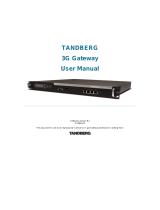
The TANDBERG Gateway is built on a standard 19-inch rack mounted chassis of only 1U in
height.
2.1 Software
In the standard version, the TANDBERG Gateway supports up to 2 Mbps bandwidth on ISDN.
With the bandwidth option installed, it can handle up to 4 Mbps bandwidth on ISDN.
3 Operation and User Interface
The TANDBERG Gateway is normally controlled via the web interface. The TANDBERG
Gateway can also be controlled via Telnet (or the RS232 port) by using a comprehensive set of
API commands
1
. This enables the TANDBERG Gateway to be controlled by a different user
interface, such as an AMX or Crestron system.
For information on how to operate the system, please see the documents TANDBERG Gateway
User Manual or TANDBERG Gateway API supplied with the system.
1
Please, refer to document ‘
TANDBERG Gateway API’ (D13202)

Technical Description of TANDBERG Gateway with software version G2
D13192 Rev. 02 6
4 TANDBERG Gateway Interfaces & Features
Extensive use of industry standard interfaces and connectors ensure effortless integration of
external equipment with the TANDBERG Gateway. These interfaces can easily be controlled
via the web user interface.
4.1 Network Interfaces and Features
Network Interfaces 4 x PRI (RJ-45 Jack) Primary Rate (G.703) Interfaces
2 x Ethernet (RJ-45 Jack) LAN interfaces (10/100 Mb)
2
• 4 x PRI (RJ-45 jack) Primary Rate (G.703) interface for transmission speeds from 112
kbps up to 2 Mbps (1.5 Mbps PRI/T1).
• 2 x Ethernet (RJ-45 jack) Local Area Network interface (10/100Mb) for transmission
speeds up to 2 Mbps
2
.
4.1.1 Multiple Calls
The TANDBERG Gateway may run 8 separate simultaneous videocalls and 8 phone calls.
Please refer to the Capacity section for more information on available resources.
2
Only Ethernet port no. 1 is used in software version G2.

Technical Description of TANDBERG Gateway with software version G2
D13192 Rev. 02 7
4.1.2 PRI E1/T1 ISDN
4.1.2.1 ISDN number plan
The TANDBERG Gateway’s PRI lines may use one or more numbers for dial in. If more than
one number is used, the numbers must be consecutive.
4.1.2.2 PRI Trunk Grouping
When using more than one PRI line, the same properties for PRI 1 can be used for all PRI's by
defining them all as a trunk group.
4.1.2.3 PRI E1/T1 ISDN
The PRI interface may require an external CSU depending on the network layout. ‘Cable
Length’ in the PRI set-up menu specifies the distance from the TANDBERG Gateway to the
CSU or last repeater.
A CSU is not required if the system is within 200 m (655 ft) of the last repeater.
The TANDBERG Gateway supports the PRI protocols AT&T Custom, National ISDN and
ETSI (Euro ISDN). The AT&T and National protocols will give a total of (23*4) = 92 channels
while the ETSI protocol will give a total of (30*4) = 120 channels.
Within these protocols the following switches are supported:
Switches
Protocols supported
4ESS (AT&T) AT&T Custom
5ESS (AT&T) AT&T Custom and National ISDN
3
DMS250 (Nortel) National ISDN
DMS100 (Nortel) National ISDN
(Any switch) ETSI (Euro ISDN)
Channel hunting is provided for outgoing calls. This feature is normally used when the number
of channels needs to be specified. When no value is specified for low or high channel, they
default to 1 (low), 23 (high US) and 30 (high Europe). Default search is from high to low.
3
Dependent on the configuration of the switch

Technical Description of TANDBERG Gateway with software version G2
D13192 Rev. 02 8
Pinout of PRI E1/T1 Interface:
4
NOTE: TANDBERG recommends always using category 5 cabling.
PRI T1 (US only):
Network Service Facility (NSF) can be configured as blank/no value (i.e. NSF not used –
default) or any value between 0 and 31, to describe the service facility on the PRI/T1 line.
AT&T
Service code (ref.1)
Service
0 Disable
1 SDN (Including GSDN)
2 Toll Free Megacom (800)
3 Megacom
6 ACCUNET Switched Digital Service (incl. Switched Digital International)
7 Long Distance Service (incl. AT&T World Connect)
8 International Toll Free Service (1800)
16 AT&T MultiQuest
23 Call Redirection Service
Sprint
Service code (ref.2)
Service
MCI
Service code (ref.2)
Service
0 Reserved 1 VNET/Vision
1 Private 2 800
2 Inwatts 3 PRISM1, PRISMII, WATS
3 Outwatts 4 900
4 FX 5 DAL
5 TieTrunk
Ref. 1: AT&T TR 414859 Specification, June 1999, page 76
Ref. 2: Ascend Multiband Plus-T1/PRI, User Documentation, Page 6-8
4
The cable of use should be a straight through configuration.
PRI Pinout
1 TIP RX
2 RING RX
4 RING TX
5 TIP TX

Technical Description of TANDBERG Gateway with software version G2
D13192 Rev. 02 9
4.1.3 Dial In Services
4.1.3.1 Direct Inwards Dialing (DID)
By enabling this feature, it is possible to make a direct mapping between ISDN numbers and
H323 aliases. This requires that the PRI lines connected to the TANDBERG Gateway are
configured with a range of numbers. This range of numbers should be large enough to associate
one ISDN number to each H.323 device that is intended to make use of the DID feature.
The H.323 aliases must be a portion of the ISDN number plus a prefix.
Example:
The TANDBERG Gateway is configured to use 4 digits of the ISDN Number, and 9 as the
H.323 prefix:
An endpoint dials the ISDN number 67117780
The TANDBERG Gateway transfers the call to the H.323 Alias 97780
4.1.3.2 Interactive Voice Response (IVR)
This feature is used when one 'main' ISDN number is used for the TANDBERG Gateway. When
dialing into the TANDBERG Gateway on this number, the user will be greeted with a welcome
picture and sound. The user can then enter the H.323 Alias of the site they wish to call using
DTMF tones.
IVR should be used when one single ISDN number is to be used for the TANDBERG Gateway
and when the endpoints using H.323 should be independent of the ISDN number used for the
TANDBERG Gateway.
4.1.3.3 TCS-4
TCS-4 uses the same ISDN number as IVR. The user can add the H.323 alias to the ISDN
number separated by a * . The TANDBERG Gateway will automatically transfer the call to the
H.323 alias.
Example:
Endpoint dials 6711111*1234
Gateway will transfer the call to the H.323 alias 1234

Technical Description of TANDBERG Gateway with software version G2
D13192 Rev. 02 10
4.1.3.4 Hotline
When calling the Hotline number specified in the TANDBERG Gateway, the call is
automatically transferred to a predefined H.323 alias. This feature can be used when an operator
or helpdesk is needed.
All ISDN Dial In features (DID, IVR, TCS-4 and Hotline) can be used in any combination.
4.1.4 IP Dial Out Services
4.1.4.1 Service Prefixes
A Service Prefix is used when dialing from a H.323 endpoint to a ISDN endpoint. By dialling
the prefix, followed by the ISDN number, the call is transferred through the gateway, to the
remote site on ISDN. The service defines the type of call (telephone/video) and bandwidth for
the connection.
It is possible to define up to 20 different services on the TANDBERG Gateway.
The TANDBERG Gateway have two default services:
Service Prefix ‘0’ Video call with maximum bandwidth 384kbps
Service Prefix ‘1’ Telephone call
4.1.5 Ethernet / LAN Interface (H.323)
The TANDBERG Gateway has two RJ-45 jacks
5
for the Ethernet interface (manual or automatic
detection of 10/100Mb) and supports call rates up to 2 Mbps. The ITU-T standard H.323 v4
protocol is implemented in the TANDBERG Gateway.
The following features are specifically relevant for this network interface:
4.1.5.1 Quality of Service features (QoS)
4.1.5.1.1 IP precedence
IP precedence is a classification of packets from 0 (low priority) to 7 (high priority). The
values 6 and 7 are typically reserved for congestion control. IP precedence helps a router
select what kind of traffic to prioritise. By means of queue mechanisms, it can select
5
Ethernet port no.2 is not used in software version G2.

Technical Description of TANDBERG Gateway with software version G2
D13192 Rev. 02 11
which packets to send first and which to throw away. Some information/traffic is time
critical while other is not, and classification is used to differentiate this traffic.
One may set separate IP precedence for Signalling, Audio, Video and Data (values 1 – 7)
as well as turn IP precedence off.
The auto setting uses the following values for IP precedence:
Signalling=6
Audio/Video=4
Data=3 (e.g. FECC commands)
This means that in auto, IP precedence has the value 6 (i.e. signalling value) while both
audio and video value is 4; data value is 3. Setting the IP precedence value in system’s
menu is actually setting the signalling value. The audio/video and data values are
changed accordingly in respect to the signalling value (i.e. audio/video value = - 2; data
value = - 3).
4.1.5.1.2 Diffserv
Diffserv is an extension of IP precedence, where values from 0 to 63 (63=Highest
priority) can be set.
4.1.5.1.3 IP type of service (TOS)
TOS helps a router select a routing path when multiple paths are available.
Delay- tells router to minimize delay
Throughput- tells router to maximize throughput
Reliability- tells router to maximize reliability
Cost- tells router to minimized cost
Off- Turns TOS off
4.1.5.1.4 Resource-Reservation Protocol (RSVP)
RSVP is a protocol that allows the TANDBERG Gateway to request the network to
reserve the bandwidth needed for the IP meeting.
4.1.5.2 IP adaptive bandwidth management
• The TANDBERG Gateway never produces more traffic than needed for better
utilization of network resources. Most of the data sent in a videoconference is video
data. Thus, by incorporating smart video algorithms, the codec sends no more video
data than necessary. Little movement in the picture gives low bit rate; while a lot of
movement gives higher bit rate.
• The TANDBERG Gateway regulates outgoing and incoming media bit rates by
means of flow control signalling.

Technical Description of TANDBERG Gateway with software version G2
D13192 Rev. 02 12
An example of this is automatic adjustment of total bandwidth used when DuoVideo is
opened.
4.1.5.3 Dynamic playout buffering
Shapes the incoming data for better playout and re-sequencing of packet delivered out of
order. This ensures better lip sync.
4.1.5.4 Asymmetrical media capabilities
Audio and video protocols can be fully asymmetrical.
E.g., the TANDBERG Gateway can send H.263 and receive H.261 at the same time.
4.1.5.5 Diagnostic tools for IP
Q.931 To show Q.931 trace during a conference you need to issue the command syslog
on. One can get traces for RAS, Q.931 and H.245 with this command. It is a
complex trace and requires an extensive knowledge in H.323 signalling to be
understood.
Ping Ping is used to see if the TANDBERG Gateway is able to reach a specific IP-
address, using a mechanism in IP called ICMP. If the TANDBERG Gateway is
unable to register to its gatekeeper, or if it is unable to dial a specific endpoint,
one can use ping to see if there is at least an IP-route to the gatekeeper or to the
endpoint.
Traceroute Traceroute does exactly that; it traces the route an IP-packet takes to reach its
destination and displays all router hops. Traceroute is very useful for seeing
exactly where there is a routing-problem in the IP-network, and for checking
where transport-delay is introduced.
4.1.5.6 Latency & Jitter
Latency is defined as the time between a node sending a message and receipt of the
message by another node. The TANDBERG Gateway can handle any value of latency-
however, the higher the latency, the longer the delay in video and audio. This may lead to
conferences with undesirable delays causing participants to interrupt and speak over each
other.
Jitter is defined as the variation in latency for packets sent between two nodes in the
network. Where constant latency simply produces delays in audio and video, jitter can
have a more adverse effect. Jitter causes packets to arrive out of order or at the wrong
times, which again leads to packet loss. The TANDBERG Gateway can manage packets
with jitter up to 100ms. If excessive packet loss is detected, the TANDBERG Gateway
will downspeed the connection until acceptable packet loss is achieved.

Technical Description of TANDBERG Gateway with software version G2
D13192 Rev. 02 13
4.1.5.7 Layer 4 Ports used in H.323
The following tables describes which layer 4 ports are being used by the TANDBERG
Gateway when a call is made on an H.323 network.
TANDBERG Gateway meetings + Duo Video
Function Port Type
Gatekeeper Discovery (RAS) 1719 UDP
Q.931 Call Setup 1720 TCP
H.245 Range 5555—5587 TCP
Video Range 2326—2837 UDP
Audio Range 2326—2837 UDP
Data/FECC Range 2326—2837 UDP
4.1.5.8 IP packet sizes
Audio
The TANDBERG Gateway can receive up to 60 ms of audio in each packet. The
TANDBERG Gateway is sending 20 ms of audio in each packet, thus:
• G.711 – 160 bytes per packet
• G.728 – 40 bytes per packet
• G.722 – 160 bytes per packet
• G.722.1 – 60 bytes per packet
Video
The TANDBERG Gateway is sending maximum 1450 bytes of video per packet.
Note:
In addition, the system needs to add the following header information for each of the audio
and video packets above:
20 bytes IP-header, 8 bytes UDP-header and 12 bytes RTP-header (i.e. 40 bytes in total).

Technical Description of TANDBERG Gateway with software version G2
D13192 Rev. 02 14
4.1.5.9 Intelligent Packet Loss Recovery (IPLR)
IPLR is an ITU standards based packet loss compensation for H.323 that improves received
video into the TANDBERG Gateway. IPLR supports all video protocols and resolutions that
TANDBERG Gateway already has implemented and is compatible with all terminals.
IPLR is a special algorithm developed at TANDBERG that will make efforts to reconstruct
the lost packets and reduce the visual effects caused by packet losses.
• If the TANDBERG Gateway experiences packet loss from an endpoint, it will ask the
endpoint to handle packet loss. This requires Intelligent Packet Loss Recovery
functionality on the endpoint.
• If an endpoint experiences packet loss from the TANDBERG Gateway, the
TANDBERG Gateway encoder will not start IPLR since this would affect the received
video quality for the other endpoint.

Technical Description of TANDBERG Gateway with software version G2
D13192 Rev. 02 15
4.1.6 LEDs Description
The TANDBERG Gateway has 24 LEDs (Light Emitting Diodes) on the front panel. Each
giving various information, as shown below.
4.1.6.1 Description of PRI Alarms
A PRI cable consists of four wires (2 pairs of wires): One pair for Transmit (TX) and one pair
for Receive (RX) signals.
Red Alarm
Red alarm or Loss of signal (LOS) means that there is no signal and thus no framing info
received. (This has same effect as pulling out the PRI cable).
Yellow Alarm
Yellow alarm or Remote Alarm Indicator (RAI) means that the TANDBERG Gateway is
receiving framing info, but in this framing info the other side tells the TANDBERG Gateway
that it is not reading the TANDBERG Gateway’s transmitted framing info. Typically, this may
be a broken connector in the TX part of the TANDBERG Gateway PRI cable. This could also
indicate weak or noisy signal in the TX part of the TANDBERG Gateway PRI cable.
Blue Alarm
Blue alarm means that network on the far side of the CSU is unavailable.

Technical Description of TANDBERG Gateway with software version G2
D13192 Rev. 02 16
Scenario: TANDBERG Gateway is connected via a CSU (i.e. a NT ‘Network Termination’) as
follows:
TANDBERG Gateway –cableA–CSU–cableB–Network
If a CSU loses framing/sync from the network (example: a bad cable B), it shall no longer send
valid framing out on cable A towards the TANDBERG Gateway. Instead it transmits "Blue
Alarm". Seen from the TANDBERG Gateway receiving blue alarm, this means that the network
on the far side of the CSU is unavailable.
4.1.7 Intelligent Call Management (ICM)
By using TANDBERG's inbuilt Intelligent Call Management (ICM), TANDBERG Gateway
conferences can be made from data rates up to 2 Mbps via ISDN networks.
ICM is a highly sophisticated feature provided by the TANDBERG Gateway that e.g. makes the
connection between two sites more reliable and safe. If the ISDN network drops channels
during a meeting, the conference will not shut down but adjust to the remaining number of
available channels
6
. This ability is called ‘Downspeeding’ and is in accordance to the
BONDING Mode 1 standard.
By defining a maximum bandwidth for the different services (DID, IVR, TCS-4, Hotline, H.323
services), all connections will be restricted to these bandwidths.
If the requested bandwidth is not available in the TANDBERG Gateway or in the receiving
endpoint, the TANDBERG Gateway will set up the connection using the available resources.
6
If the connected site does not support downspeeding, the site will drop out of the call.

Technical Description of TANDBERG Gateway with software version G2
D13192 Rev. 02 17
4.1.8 TANDBERG Gateway Capacity
The total capacity of the TANDBERG Gateway is defined by the following rules.
I. Maximum 8 video calls and 8 telephones calls.
II. Total system bandwidth (IP + ISDN) of the TANDBERG Gateway is 7680 kbps. The
maximum bandwidth used for ISDN calls is depending on the number and type of
PRI's installed:
a) The maximum bandwidth for each ISDN E1 is 1920 kbps (30x64kbps).
b) The maximum bandwidth for ISDN T1 is 1472 kbps (23x64kbps).
III. In addition, each call has a Call Weight depending on bandwidth and encryption as
follows:
Video calls:
Bandwidth
64
128 192 256 320 384 512 768 1152 1472 1920
Non-encr.
74 80 82 84 88 92 108 124 160 176 220
Encrypted
106 118 120 122 136 146 168 222 N/A N/A N/A
Telephone calls:
Bandwidth Telephone
Non-encr.
22
Encrypted
N/A
The total sum of the Call Weights on the TANDBERG Gateway can not exceed 845.
(Users will be prevented from setting up calls that exceeds this limit).
Example of call weight calculation:
If the TANDBERG Gateway has made 1 encrypted call at 768kbps and two unencrypted calls at
384kbps the calculation will be:
222 + 2(92) = 222 + 184 = 406
Since 406 is less than 845, this will be OK.

Technical Description of TANDBERG Gateway with software version G2
D13192 Rev. 02 18
4.1.8.1 TANDBERG Gateway Capacity – typical scenarios for 4Mb Option
In the table below some typical capacity scenarios are listed (they can be derived by the
calculation above):
Bandwidth Non-encrypted
(Max. no. of video
calls + telephone
calls) IP & E1
Encrypted
(Max. no. of video
calls)
128 kbps 8 + 8 7
256 kbps 8 + 7 6
384 kbps 8 + 4 5
512 kbps 7 + 4 5
768 kbps 5 + 0 3
1472 kbps
(1.5Mbps)
2 + 8 N/A
1920 kbps (2Mbps) 2 + 0* N/A
*) Limited by the maximum capacity 7680 kbps, see rule II a) above.
4.1.9 Secure Conference (Encryption)
The TANDBERG Gateway has built-in encryption of audio, video and data for both H.323
(based on ITU standard H.235) and H.320 (based on ITU standard H.233 and H.234).
The encryption algorithms used in the TANDBERG Gateway and all other TANDBERG
systems are:
- The Data Encryption Standard (DES) with a 56 bits session key
- The Advanced Encryption Standard (AES) with a 128 bits session key
Although there are small differences between H.323 and H.320, a typical set-up of a secure call
can be defined as follow:
1. Establishement of a common shared secret and selection of a encryption algorithm.
2. Exchange of the keys according to the common shared secret and the selected encryption
algorithm.
3. Start the encryption.
The establishment of the common shared secret is done through the computation of the Diffie-
Hellman (DH) algorithm. The DH method uses primes numbers of 512 bits length for DES and
1024 bits for AES. The shared secret is then used as a key for the selected encryption algorithm

Technical Description of TANDBERG Gateway with software version G2
D13192 Rev. 02 19
which encrypts "the session keys". When the session are collected by the remote end, encryption
of the audio, video and data channels can start.
The encryption will be established automatically when both endpoints in the conference
supports encryption with automatic key generation (and the conference is set up for encryption
mode of operation).
Encryption is supported for meetings up to 768 kbps and for the TANDBERG feature
DuoVideo.
Note: For an encrypted call, the endpoints must support encryption (AES or DES).
If encryption is enabled, the TANDBERG Gateway accepts both AES and DES encryption.
If one of the sites does not support encryption, encryption on both sides is disabled.
4.1.10 H.243 Multipoint Transparency
All MCU commands and information signalling are transparent through the
TANDBERG Gateway. The most important commands and information signals are:
- Request/Release floor
- Site Naming
- Cascading Signalling
- OnAir Signalling
- Microphone Off signalling(not supported by IP endpoint)

Technical Description of TANDBERG Gateway with software version G2
D13192 Rev. 02 20
4.2 Aggregation Standards
ISDN Aggregation H.221 Frame Structure from 64 (56
*
) kbps to 128 kbps
ISO 13871 BONDING, Mode 1 from 64 (56
*
) kbps to 2 Mbps
H0 One 384 kbps channel
4.2.1 BONDING
• ISO 13871, BONDING Mode 1 for bit rates from 56 kbps up to 2 Mbps (1 to 30 channels).
• The maximum relative delay difference between B-channels is 0.5 second (i.e. to compensate
for different routing of channels).
The following are the standard bandwidths on H.320:
30ch – 24 – 23 – 18 – 12 – 8 – 6 – 5 – 4 – 3 – 2 – 1
4.2.1.1 ISDN channel set-up
The following is a description of how the ISDN channels are set up.
Incoming & Outgoing TANDBERG Gateway calls: Normally the TANDBERG Gateway will
set up only 1 channel from PRI 1 and build up the channels starting from the 'bottom' of the last
PRI in use.
This will ensure that the TANDBERG Gateway always have available channels on the first PRI
number (which normally should be the TANDBERG Gateway 's main number).
4.2.2 H.221
• For bit rates from 56 kbps up to 128 kbps (1 or 2 channels).
• The maximum relative delay difference between the 2 B-channels is 0.6 second.
4.2.3 H0
H0 is an ITU defined 384 kbps service available for ISDN PRI. The TANDBERG Gateway
supports H0 on incoming ISDN calls. H0 is defined as a group of 6 ISDN channels multiplexed
to provide one 384 kbps channel. H0 may have a shorter connection time, since there is only
one channel to set up.
This service is sometimes called Switched 384 or ISDN H0.
1/40