Page is loading ...

Software version G2
D13187-02
This document is not to be reproduced in whole or in part
without permission in writing from:
User Manual
Gateway
GW

2
TANDBERG Gateway

TANDBERG Gateway
3
Environmental Issues
Thank you for buying a product which contributes to a reduction in pollution and thereby helps save the environment.
Our products reduce the need for travel and transport and thereby reduce pollution.
Our products have either no or few consumable parts (chemicals, toner, gas, paper).
Our products are low energy consuming products.
Waste handling:
There is need to send material back to TANDBERG. Please contact your local dealer for information on recycling the product by sending the
main parts of the product for disassembly at local electronic waste stations.
Production of products:
Our factories employ the most efficient environmental methods for reducing waste and pollution by ensuring that the products are recyclable.
Trademarks and copyright
COPYRIGHT © 2003, TANDBERG
Philip Pedersensvei 22
1366 Lysaker, Norway, Tel: +47 67 125 125, Fax: +47 67 125 234
All rights reserved. This document contains information that is proprietary to TANDBERG. No part of this publication may be reproduced,
stored in a retrieval system, or transmitted, in any form, or by any means, electronically, mechanically, by photocopying, or otherwise, without
the prior written permission of TANDBERG. Nationally and internationally recognized trademarks and tradenames are the property of their
respective holders and are hereby acknowledged.
Portions of this software are © 1996-2003 RADVision Ltd. All intellectual property rights in such portions of the Software and documentation
are owned by RADVision and are protected by United States copyright laws, other applicable copyright laws and international treaty provisions.
RADVision and its suppliers retain all rights not expressly granted.
This product includes patent-pending People & Content technology© Polycom, Inc. People & Content is a trademark of Polycom, Inc.
Disclaimer
The information in this document is furnished for informational purposes only, is subject to change without prior notice, and should not be
construed as a commitment by TANDBERG.
The information in this document is believed to be accurate and reliable, however TANDBERG assumes no responsibility or liability for any
errors or inaccuracies that may appear in this document, nor for any infringements of patents or other rights of third parties resulting from its
use. No license is granted under any patents or patent rights of TANDBERG.
This document was written by the Technical Support Department of TANDBERG, Norway. We are committed to maintaining a high level of
quality in all our documentation. Towards this effort, we welcome your comments and suggestions regarding the content and structure of this
document. Please fax or mail your comments and suggestions to the attention of:
TANDBERG
Attn: Product Support Department
P.O.Box 92
1325 Lysaker, Norway
Tel: +47 67 125 125
Fax: +47 67 125 234

4
TANDBERG Gateway
Operator Safety Summary
For your protection, please read these safety instructions completely before operating the equipment and keep this manual for future
reference. The information in this summary is intended for operators. Carefully observe all warnings, precautions and instructions both
on the apparatus and in the operating instructions.
Equipment Markings
The lightning flash symbol within an equilateral triangle is intended to alert the user to the
presence of uninsulated “dangerous voltages” within the product’s enclosure that may be of
sufficient magnitude to constitue a risk of electrical shock.
The exclamation mark within an equilateral triangle is intended to alert the user to the presence of
important operating and maintenance (servicing) instructions within literature accompanying the
equipment.
Warnings
Water and moisture - Do not operate the equipment under or near water - for example near a bathtub, kitchen sink, or laundry tub, in a wet
basement, near a swimming pool or in areas with high humidity.
Cleaning - Unplug the apparatus from the wall outlet before cleaning or polishing. Do not use liquid cleaners or aerosol cleaners. Use a lint-free
cloth lightly moistened with water for cleaning the exterior of the apparatus.
Ventilation - Do not block any of the ventilation openings of the apparatus. Install in accordance with the installation instructions. Never cover
the slots and openings with a cloth or other material. Never install the apparatus near heat sources such as radiators, heat registers, stoves, or
other apparatus (including amplifiers) that produce heat.
Grounding or Polarization - Do not defeat the safety purpose of the polarized or grounding-type plug. A polarized plug has two blades with one
wider than the other. A grounding type plug has two blades and a third grounding prong. The wide blade or third prong is provided for your
safety. If the provided plug does not fit into your outlet, consult an electrician.
Power-Cord Protection - Route the power cord so as to avoid it being walked on or pinched by items placed upon or against it, paying particular
attention to the plugs, receptacles, and the point where the cord exits from the apparatus.
Attachments - Only use attachments as recommended by the manufacturer.
Accessories - Use only with a cart, stand, tripod, bracket, or table specified by the manufacturer, or sold with the
apparatus. When a cart is used, use caution when moving the cart/apparatus combination to avoid injury from tip-over.
Lightning - Unplug this apparatus during lightning storms or when unused for long periods of time.
ISDN cables - CAUTION - To reduce the risk of fire, use only No. 26 AWG or larger telecommunication line cord.
Servicing - Do not attempt to service the apparatus yourself as opening or removing covers may expose you to
dangerous voltages or other hazards, and will void the warranty. Refer all servicing to qualified service personnel.
Damaged Equipment - Unplug the apparatus from the outlet and refer servicing to qualified personnel under the
following conditions:
When the power cord or plug is damaged or frayed
If liquid has been spilled or objects have fallen into the apparatus
If the apparatus has been exposed to rain or moisture
If the apparatus has been subjected to excessive shock by being dropped, or the cabinet has been damaged
If the apparatus fails to operate in accordance with the operating instructions

TANDBERG Gateway
5
IMPORTANT
PLEASE READ THIS
SECTION
CAREFULLY
FOR
OPTIMAL
SYSTEM
SET-UP.
Contents
Introduction ........................................................................................ 7
The TANDBERG Gateway .............................................................................. 8
Installation ........................................................................................ 10
Precautions ................................................................................................... 10
Unpacking ..................................................................................................... 10
Installation site preparations .......................................................................... 11
Rack Mounting (optional) ............................................................................... 11
Connecting cables ........................................................................................ 12
Gateway Configuration .................................................................................. 13
Gateway start-up ........................................................................................... 14
Accessing the gateway ................................................................................. 14
Call Overview ................................................................................................ 15
Using the Gateway ........................................................................... 15
Dial from ISDN .............................................................................................. 19
Dial from IP.................................................................................................... 22
Features ........................................................................................................ 23
Manage the Phone Book ............................................................................... 25
View System Status ......................................................................... 27
PRI Status ..................................................................................................... 27
H.323 Status .................................................................................................. 29
System Information ....................................................................................... 29
Available Resources ..................................................................................... 30
Configure the Gateway .................................................................... 31
System Configuration .................................................................................... 31
IP Configuration ............................................................................................. 36
H.323 Configuration ....................................................................................... 38
Dataport Configuration .................................................................................. 40
SNMP Configuration ...................................................................................... 41
Miscellaneous Configuration ......................................................................... 42
Software Upgrade ......................................................................................... 44
File Management ........................................................................................... 45
NOTE

6
TANDBERG Gateway
ISDN Dial In Configuration ............................................................................. 46
H.323 Services .............................................................................................. 49
Gateway Features ......................................................................................... 52
Appendices ...................................................................................... 54
Appendix 1: Using the file system .................................................................. 54
Appendix 2: Declaration of Conformity .......................................................... 55
Appendix 3: Capacity ..................................................................................... 56
Index ................................................................................................. 57

TANDBERG Gateway
7
Introduction
Introduction
This User Manual is provided to help you make the best use of your TANDBERG Gateway. The gateway enables
sites on IP and sites on ISDN to participate in meetings with each other, and at the same time it offers superior
quality and ease of use in one fully-featured gateway (GW).
Main Features:
• Flexible ISDN Dial-in Services - Direct Inward Dialing (DID), Interactive Voice Response (IVR), Terminal Control
Session 4 (TCS-4) and Hotline/Operator Mode.
• Flexible IP Dial-out Services - Downspeeding
TF
, Service Prefix and Load balance.
• Up to 8 video sites and 8 telephony calls can supported at the same time, each benefiting from the same
superb audio and video quality, and full featured TANDBERG functionality.
• Call rate of up to 2 Mbps for each call is supported through the gateway.
• A maximum of 4 Mbps (2 Mbps standard) ISDN bandwidth is supported through the gateway.
• Secure Conference
TF
- using standard based AES 128 and DES encryption.
• Superb video quality supporting the new ITU video standard H.264.
• Dual Stream - support for Duo Video
TF
on both ISDN and IP, and People+Content on ISDN.
• Full H.243 Multipoint Control Unit (MCU) Transparency, for seamless MCU connection through the gateway.
• Secure Access - support XML/SOAP over HTTPS, Web (HTTP) encrypted password and the services Telnet,
FTP, HTTP, HTTPS and SNMP can be disabled.
• Web-interface for system management, call management such as call transfer, diagnostics and software
uploads.
• Worldwide compatibility with standards-based videoconferencing systems.
Options:
• Management using TANDBERG Management Suite.
• Scheduling using TANDBERG Scheduler. Simplifies scheduling and the use of video meeting resources through
highly automated functionality.
HELPFUL TIPS AND NOTES WILL APPEAR LIKE THIS.
TIP

8
TANDBERG GatewayIntroduction
Front view
The front of the gateway contains 24 Light Emitting Diodes (LEDs) organized in three groups. These diodes
provide information about PRI-line status, LAN (Ethernet) connection and power.
The TANDBERG Gateway
Red Alarm or Loss of signal (LOS) indicates that there is no signal and thus no framing info received. The same
effect will be obtained by pulling out the PRI cable. This may also be caused by a broken connector in the receive
(RX) part of the cable.
Yellow Alarm or Remote Alarm Indicator (RAI) means that the gateway is receiving framing info, but in this
framing info the other side tells the gateway that it is not reading the gateway’s transmitted framing info. Typically,
this may be a broken connector in the transmit (TX) part of the PRI cable. This could also indicate weak or noisy
signal in the transmit (TX) part of the PRI cable.
G
reen
: Layer 1 O
K
R
ed
: D
-C
hannel D
ow
n
R
ed
: Layer 1 R
ed A
larm
Y
ello
w
: Layer 1 Y
ellow
A
larm
G
reen:
Layer 1 O
K
R
ed
: D
-C
hannel D
ow
n
R
ed
: Layer 1 R
ed A
larm
Y
ello
w
: La
yer 1 Y
ellow
A
larm
G
reen
: Layer 1 O
K
R
ed
: D
-C
hannel D
ow
n
R
ed
: Layer 1 R
ed A
larm
Y
ello
w
: Layer 1 Y
ellow
A
larm
G
reen
: Layer 1 O
K
R
ed
: D
-C
hannel D
ow
n
R
ed
: Layer 1 R
ed A
larm
Y
ello
w
: Layer 1 Y
ellow
A
larm
G
reen
: T
x
G
reen
: R
x
G
reen
: T
x
G
reen
: R
x
G
reen
: N
ot in use
G
reen
:
P
ow
er on
G
reen
: N
ot in
use
G
re
en
: N
ot in use
GW

TANDBERG Gateway
9
Introduction
Rear view
The back panel provides four PRI interfaces, two LAN interfaces and one RS 232 interface located together with
the power switch/connector and four cooling fans.
THE ‘LAN 2’ CONNECTOR IS NOT USED.
FOR MORE DETAILS ON CAPACITY, SEE ‘APPENDIX 3: CAPACITY’
TIP
GATEWAY Capacity – typical scenarios (4 Mbps option)
Below is an overview of the number of video calls possible to connect on different bandwidths, when 2xE1 (or
3xT1) PRI ISDN lines are connected. In addition to the video calls, telephone calls can also be made through the
gateway.
Bandwidth Non-encrypted Encrypted
128 kbps 8+8* 7+0
256 kbps 8+7 6+5**
384 kbps 8+4 5+5
512 kbps 7+4 5+0
768 kbps 5+0 3+8
1472 kbps (1.5 Mbps) 2+8 N/A
1920 kbps (2 Mbps) 2+0 N/A
* 8+8 indicates 8 video calls and 8 telephone calls.
** 6+5 indicates 6 encrypted video calls and 5 unencrypted telephone calls.
I
o
LAN 1 LAN 2 PRI 1 PRI 2 PRI 3 PRI 4 RS 232
NOTE

10
TANDBERG GatewayInstallation
Precautions
• Never install telephone wiring during a lightning storm.
• Never install telephone jacks in wet locations unless the jack is specifically designed for wet locations.
• Never touch uninstalled telephone wires or terminals unless the telephone line has been disconnected at the network interface.
• Use caution when installing or modifying telephone lines.
• Avoid using a telephone (other than a cordless type) during an electrical storm. There may be a remote risk of electrical shock from
lightning.
• Do not use the telephone to report a gas leak in the vicinity of the leak.
• The socket outlet shall be installed near to the equipment and shall be easily accessible.
• Never install cables without first switching the power OFF.
• This product complies with directives: LVD 73/23/EC, EMC 89/366/EEC, R&TTE 99/5/EEC.
• This product complies with the standards GR-63-CORE and GR-1089-CORE and is NEBS approved by UL .For NEBS compliance, the
product should be installed in the following manner:
- Use the enclosed rack brackets marked “NEBS”.
- There should be a clearance of 9.1cm between the product and any other product mounted in the rack.
Installation
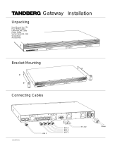
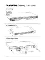
Unpacking
To avoid damage to the unit during transportation, the gateway is delivered in a special shipping box, which should
contain the following components:
• TANDBERG GW.
• User Manual and other documentation on CD.
• Rack-ears, screws and screwdriver.
• Cables:
• Power cable
• Four ISDN PRI cables
• Ethernet cable
• RS232 cable

TANDBERG Gateway
11
Installation
Installation site preparations
• Make sure that the gateway is accessible and that all cables can be easily connected.
• For ventilation: Leave a space of at least 10cm (4 inches) behind the gateway’s rear panel and 10cm (4 inches)
in front of the front panel.
• The room in which you install the gateway should have an ambient temperature between 0
o
C and 35
o
C (32
o
F
and 95
o
F) and between 10% and 90% non-condensing relative humidity.
• Do not place heavy objects directly on top of the gateway.
• Do not place hot objects directly on top, or directly beneath the gateway.
• Use a grounded AC power outlet for the gateway.
• You will need a CSU (Channel Service Unit) between your system and the PRI line from your network provider.
Rack Mounting (optional)
The gateway comes with brackets for mounting in standard 19” racks.
1. Disconnect the AC power cable.
2. Make sure that the mounting space is according to the ‘Installation site preparations’ (see above).
3. Attach the brackets to the gateway on both sides of the unit.
4. Insert the gateway into a 19” rack, and secure with screws in the front (four screws).
BEFORE STARTING THE RACK MOUNTING, PLEASE MAKE SURE THE TANDBERG GW IS PLACED SECURELY ON A HARD, FLAT SURFACE.
NOTE

12
TANDBERG GatewayInstallation
Connecting cables
Power cable
Connect the system power cable to an electrical distribution socket.
ISDN PRI cables
For each of the four PRI interfaces, the E1/T1 cable should be connected to a CSU (Channel Service Unit). You will
need a CSU between your gateway and the PRI line from your network provider.
LAN cable
To use the gateway on IP, connect a LAN cable from the ‘LAN 1’ connector on the gateway to your network. The
LAN 2’ connector is not used and should be left open.
RS 232 cable
To control the gateway using the dataport, connect an RS 232 cable between the gateway’s RS 232 connector
and the COM-port on a PC. For further information, please refer to the ‘Dataport’ chapter in ‘Configure the
Gateway’.
RS 232
PRI 4
PRI 3
PRI 2
PRI 1
LAN 1
Power
LAN 1 LAN 2
PR
I 1 PR
I 2
PR
I 3
PR
I 4
R
S
2
32
o
I

TANDBERG Gateway
13
Installation
Gateway Configuration
The gateway requires some basic configurations before it can be used. It will be necessary to find the IP-address
and program the ISDN-PRI Line numbers.
To do this configuration, follow the instructions below:
1. Connect the RS232 cable between the gateway and a PC and then switch on the gateway.
2. Start a terminal program on the PC and configure it to: 9600, 8, 1, None.
3a. To assign a static IP-address, type ‘ipassign static’ and ‘ipaddress 1 static <IP-address>’.
3b. To assign an IP Subnetmask, type ‘ipaddress 1 subnetmask <subnetmask>’.
3c. To assign an IP Gateway address, type ‘ipaddress 1 gateway <gateway IP-address>’.
4. Restart the gateway.
5. Start a WEB browser and enter the IP-address of the gateway. Default password: ‘TANDBERG’.
6. To configure the gateway for ISDN dial in, enter PRI numbers and dial in number(s). For details, see
the ‘PRI Configuration’ and the ‘ISDN Dial in Configuration’ section.
7. To configure the gateway for IP dial in, register the gateway to a gatekeeper and enter H.323
services. For details, see the ‘H.323 Services’ and ‘H.323 Configuration’ sections.
TIP
DHCP ASSIGNED IP-ADDRESSES ARE SUPPORTED BY THE TANDBERG GATEWAY (FACTORY DEFAULT).

14
TANDBERG GatewayInstallation
GW
Accessing the gateway
You may access the gateway by entering the IP-address of the gateway in a standard WEB-browser. You will
then be asked to enter a password. It is not necessary to enter ‘User Name’. The default password for the
gateway is ‘TANDBERG’. Remember that the password is case sensitive.
IF YOU DO NOT KNOW THE IP-ADDRESS, PLEASE FOLLOW THE
PROCEDURE IN ‘INSTALLATION’, ‘SYSTEM CONFIGURATION’.
TIP
THE PASSWORD CAN BE CHANGED IN ‘SYSTEM CONFIGURATION’,
‘MISC’. SEE ALSO THE ‘CONFIGURE MISCELLANEOUS PARAMETERS’
SECTION IN ‘CONFIGURE THE GATEWAY’.
TIP
Gateway start-up
To start the gateway, please make sure that the power cable is connected, and press the power switch button
to ‘1’.
On the front panel of the system the power indicator LED, marked ‘Pwr’, will now turn GREEN.

TANDBERG Gateway
15
Using the Gateway
Using the Gateway
The following Web-page, called ‘Overview’ will be shown when the correct password has been entered and
shows all calls currently active through the gateway.
Call Overview
GW Calls
Shows each active call through the gateway.
[Idle] No call is active.
Active Call A call is active. Click on Active Call to see call info in details.

16
TANDBERG Gateway
Using the Gateway
Source
Shows the Status of the incoming call to the gateway, the Number and which Network the incoming call is using.
Idle No active call, call just been disconnected.
Alerting Call is being connected.
Connected Call is connected.
Clear out Call is being disconnected.
Number ISDN or IP number.
ISDN Call connected is using the H.320 protocol over ISDN.
IP/H.323 Call connected is using the H.323 protocol over IP.
Destination
Shows the Status of the outgoing call from the gateway, the Number and which Network the call is using.
Idle No active call, call just been disconnected.
Establ out Gateway is calling out to destination.
Alerting Call is being connected.
Connected Call is connected.
Clear out Call is being disconnected.
Number ISDN or IP number.
ISDN Call connected is using the H.320 protocol over ISDN.
IP/H.323 Call connected is using the H.323 protocol over IP.
Duration
Shows the length of the current call.
Encryption (Secure conference
TF
)
The gateway supports Secure Conference DES and AES.
The single padlock symbol indicates that DES (56 bit) encryption is used.
The double padlock symbol indicates that AES (128 bit) encryption is used.
Indicates that the call is not encrypted.
ENABLING ENCRYPTION WILL REDUCE THE CAPACITY OF THE
GATEWAY.
NOTE

TANDBERG Gateway
17
Using the Gateway
Actions
When a call is active, the Administrator or Operator has the possibility to disconnect the call, or transfer the call
from one IP endpoint to another.
Disconnect Gateway Call
Will disconnect the selected gateway call. A confirmation window will be shown.
Call Transfer
Will open the H.323 Call Transfer window. Here the Administrator or Operator can select an IP entry from
the Phone Book or enter a H.323 Alias/IP address and transfer the H.323 (IP) call to another IP endpoint.
If the transfer fails, the call will be disconnected.
Status
Shows current status on the PRI and IP status.
PRI:
Minimum one PRI line is synced and active. Click on More... to see status in detail.
No PRI lines are active. Click on More... to see status in detail.
IP/H.323:
The gateway is registered with a Gatekeeper. Click on More... to see status in detail.
The gateway is not registered with a Gatekeeper. Click on More... to see status in detail.

18
TANDBERG Gateway
Using the Gateway
Usage
The usage bar shows the current status of all the available resources (CPU, ISDN channels and number of calls)
When the Resource Usage reaches the “Busy on Load”-limit, the gateway will try to route outgoing IP calls to
other gateways. This is done to maintain availability for incoming ISDN calls when using multiple gateways.
Resource Usage 90%. Click on Usage to see resource usage in detail.
H.323 Busy on Load> 70%. Click on on Load to adjust the value.
ISDN Numbers
Shows the available ISDN dial-in numbers for IVR,
TCS-4, DID and Hotline.
H.323 Numbers
Shows the available H.323 Services (dial-out prefixes)
for accessing/dialing the ISDN network.
FOR MORE INFO ABOUT IVR, HOTLINE OR DID, PLEASE READ THE
‘DIAL FROM ISDN’ SECTION IN ‘USING THE GATEWAY’.
TIP
FOR MORE INFO ABOUT H.323 SERVICES, PLEASE READ THE ‘DIAL
FROM IP’ SECTION IN ‘USING THE GATEWAY’.
TIP

TANDBERG Gateway
19
Dial from ISDN
Dial from ISDN
The gateway supports four different ISDN Dial In services:
• IVR
• IVR + TCS4
• DID
• Hotline
Any of these services can be enabled or disabled, but at least one must be enabled for incoming call routing to
take place.
In order to enable parallel incoming calls, a PRI number range must be defined.
IVR
Interactive Voice Response (IVR), also called extention dial-in, is an automated answering system that directs the
call to the IP endpoint indicated by the caller. The caller uses telephone tones (DTMF) to enter the H.323 Alias or
extention.
IVR is useful if you have limited PRI numbers on your PRI line.
Example:
• A videoconferencing system calls into the Extention Dial In number with IVR active.
• The gateway activates the ‘Welcome’ picture and sound.
• The videoconferencing system enters the extention (H.323 Alias) followed by the # (pound-sign) to
indicate end of number.
• The gateway starts to call the IP endpoint and the “Call proceeding” picture and sound are activated.
• When the call is connected audio and video are transmitted through the gateway.
THE WELCOME PICTURE AND SOUND CAN BE CHANGED IN THE
‘FILE MANAGEMENT’ SECTION IN ‘CONFIGURE THE GATEWAY’.
TIP
FOR MORE DETAILS ON ISDN DIAL IN SERVICES, SEE ‘ISDN
DIAL IN CONFIGURATION’ UNDER ‘CONFIGURE THE GATEWAY’.
TIP

20
TANDBERG Gateway
Dial from ISDN
IVR + TCS-4
IVR + Terminal Control Session 4 (TCS-4) is an extention dial-in method that combines IVR with TCS-4. In this
mode the extention number can be indicated with telephone tones (DTMF) or TCS-4 signaling.
TCS-4 allow an ISDN based videoconferencing endpoint to dial an IP endpoint directly, without having to go
through the same procedure as for IVR. If no TCS-4 extention is given from the endpoint, then IVR will be used.
To use TCS-4, it needs to be supported by the videoconferencing endpoint. Refer to the User Manual of the
videoconferencing endpoint to see how TCS-4 is supported.
Example:
• A videoconferencing endpoint calls into the Extention Dial In number with IVR + TCS-4 active, using
<Extention Dial In number of gateway><*><party’s extention>.
• The gateway starts to call the IP endpoint and the “Call proceeding” picture and sound are activated.
• When the call is connected audio and video are transmitted through the gateway.
DID
Direct Inward Dialing (DID) will provide you with direct ISDN numbers for your IP endpoints. I.e. it will do a direct
mapping between your ISDN number and the H.323 Alias.
In order to use DID you will need to have assigned multiple ISDN numbers to your ISDN PRI line, as each ISDN
number will map to a single IP endpoint.
We also recommend that if more than one PRI line is used all PRI lines should have the same numbers (use trunk
groups).
Example:
• Your ISDN PRI number range is from 67124000 to 67124050 and DID is enabled.
• You want your IP endpoints to have the numbers (H.323 Alias) in the range 94000 - 94050.
• In the ISDN Dial In Configuration, set ‘No. Significant Digits’ to 4 and ‘Prefix (E.164)’ to 9.
• To call an IP endpoint with H.323 Alias 94020 from ISDN, dial the ISDN number 67124020.
• The gateway starts to call the IP endpoint and the “Call proceeding” picture and sound are activated.
• When the call is connected audio and video are transmitted through the gateway.
THE ‘*’ IS SPECIFIC TO TANDBERG ENDPOINTS. OTHER
VENDORS
WILL HAVE DIFFERENT METHODS OF ENTERING THE
TCS-4 EXTENTION.
NOTE
/