Page is loading ...

TANDBERG
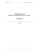
3G Gateway
User Manual
Software version R2
D1384102
This document is not to be reproduced in whole or in part without permission in writing from:

TANDBERG 3G Gateway User Manual
Trademarks and copyright
All rights reserved. This document contains information that is proprietary to TANDBERG. No
part of this publication may be reproduced, stored in a retrieval system, or transmitted, in any
form, or by any means, electronically, mechanically, by photocopying, or otherwise, without
the prior written permission of TANDBERG. Nationally and internationally recognized
trademarks and trade names are the property of their respective holders and are hereby
acknowledged.
Copyright (c) 1992, 1993, The Regents of the University of California. All rights reserved.
This code is derived from software contributed to Berkeley by Christos Zoulas of Cornell
University. Redistribution and use in source and binary forms, with or without modification, are
permitted provided that the following conditions are met:
Redistributions of source code must retain the above copyright notice, this list of
conditions and the following disclaimer.
Redistributions in binary form must reproduce the above copyright notice, this list of
conditions and the following disclaimer in the documentation and/or other materials
provided with the distribution.
All advertising materials mentioning features or use of this software must display the
following acknowledgement:
o This product includes software developed by the University of California,
Berkeley and its contributors.
Neither the name of the University nor the names of its contributors may be used to
endorse or promote products derived from this software without specific prior written
permission.
This software is provided by the Regents and contributors ‘as is’ and any express or implied
warranties, including, but not limited to, the implied warranties of merchantability and fitness
for a particular purpose are disclaimed. In no event shall the Regents or contributors be liable
for any direct, indirect, incidental, special, exemplary, or consequential damages (including,
but not limited to, procurement of substitute goods or services; loss of use, data or profits; or
business interruption) however caused and on any theory of liability, whether in contract, strict
liability, or tort (including negligence or otherwise) arising in any way out of the use of this
software, even if advised of the possibility of such damage.
Disclaimer
The information in this document is furnished for informational purposes only, it is subject to
change without prior notice, and should not be construed as a commitment by TANDBERG.
The information in this document is believed to be accurate and reliable, however
TANDBERG assumes no responsibility or liability for any errors or inaccuracies that may
appear in this document, nor for any infringements of patents or other rights of third parties
resulting from its use. No license is granted under any patents or patent rights of
TANDBERG.
ii

TANDBERG 3G Gateway User Manual
This document was written by the Research and Development Department of TANDBERG,
Norway. We are committed to maintain a high level of quality in all our documentation.
Towards this effort, we welcome you to
Contact us with comments and suggestions regarding
the content and structure of this document.
COPYRIGHT © 2006, TANDBERG
iii

TANDBERG 3G Gateway User Manual
Environmental Issues
Thank you for buying a product which contributes to a reduction in pollution, and thereby
helps save the environment. Our products reduce the need for travel and transport and
thereby reduce pollution. Our products have either none or few consumable parts (chemicals,
toner, gas, paper). Our products are low energy consuming products.
TANDBERG’s Environmental Policy
TANDBERG’s Research and Development is continuously improving TANDBERG’s
products towards less use of environmentally hazardous components and substances
as well as to make the products easier to recycle.
TANDBERG's products are Communication Solutions. The idea of these solutions is
to reduce the need for expensive, time demanding and polluting transport of people.
Through people’s use of TANDBERG’s products, the environment will benefit from
less use of polluting transport.
TANDBERG’s wide use of the concepts of outsourcing makes the company itself a
company with a low rate of emissions and effects on the environment.
TANDBERG’s policy is to make sure our partners produce our products with minimal
influence on the environment and to demand and audit their compatibility according to
applicable agreements and laws (national and international).
Environmental Considerations
Like other electronic equipment, the TANDBERG 3G Gateway contains components that may
have a detrimental effect on the environment. TANDBERG works continuously towards
eliminating these substances in our products.
Printed-wiring boards made of plastic, with flame-retardants like Chloride or Bromide.
Component soldering that contains lead.
Smaller components containing substances with possible negative environmental
effect.
After the product’s end of life cycle, it should be returned to authorize waste handling and
should be treated according to National and International Regulations for waste of electronic
equipment.
iv

TANDBERG 3G Gateway User Manual
Operator Safety Summary
For your protection, please read these safety instructions completely before operating the
equipment and keep this manual for future reference. The information in this summary is
intended for operators. Carefully observe all warnings, precautions and instructions both on
the apparatus and in the operating instructions.
Warnings
Caution risk of explosion if battery is replaced by an incorrect type. Dispose of used
batteries according to the instructions.
Water and moisture - Do not operate the equipment under or near water - for
example near a bathtub, kitchen sink, or laundry tub, in a wet basement, or near a
swimming pool or in areas with high humidity.
Cleaning - Unplug the apparatus from the wall outlet before cleaning or polishing. Do
not use liquid cleaners or aerosol cleaners. Use a lint-free cloth lightly moistened with
water for cleaning the exterior of the apparatus.
Ventilation - Do not block any of the ventilation openings of the apparatus. Install in
accordance with the installation instructions. Never cover the slots and openings with
a cloth or other material. Never install the apparatus near heat sources such as
radiators, heat registers, stoves, or other apparatus (including amplifiers) that
produce heat.
Grounding or Polarization - Do not defeat the safety purpose of the polarized or
grounding-type plug. A polarized plug has two blades with one wider than the other. A
grounding type plug has two blades and a third grounding prong. The wide blade or
third prong is provided for your safety. If the provided plug does not fit into your outlet,
consult an electrician.
Power-Cord Protection - Route the power cord so as to avoid it being walked on or
pinched by items placed upon or against it, paying particular attention to the plugs,
receptacles, and the point where the cord exits from the apparatus.
Attachments - Only use attachments as recommended by the manufacturer.
Accessories - Use only with a cart, stand, tripod, bracket, or table specified by the
manufacturer, or sold with the apparatus. When a cart is used, use caution when
moving the cart/apparatus combination to avoid injury from tip-over.
Lightning - Unplug this apparatus during lightning storms or when unused for long
periods of time.
Servicing - Do not attempt to service the apparatus yourself as opening or removing
covers may expose you to dangerous voltages or other hazards, and will void the
warranty. Refer all servicing to qualified service personnel.
Damaged Equipment - Unplug the apparatus from the outlet and refer servicing to
qualified personnel under the following conditions:
When the power cord or plug is damaged or frayed
If liquid has been spilled or objects have fallen into the apparatus
If the apparatus has been exposed to rain or moisture
If the apparatus has been subjected to excessive shock by being dropped, or
the cabinet has been damaged
If the apparatus fails to operate in accordance with the operating instructions
v

TANDBERG 3G Gateway User Manual
Contact us
If you have any questions, comments or suggestions, please see the
Online Support service
at
www.tandberg.net.
It is also possible to send a fax or mail to the attention of:
Product and Sales Support
TANDBERG
P.O. Box 92
1325 Lysaker
Norway
Tel: +47 67 125 125
Fax: +47 67 125 234
vi

TANDBERG 3G Gateway User Manual
Table of Contents
1 Introduction................................................................................................................................8
1.1 The TANDBERG 3G Gateway............................................................................................. 10
1.1.1 3G GATEWAY Capacity – typical scenarios........................................................... 11
2 Installation .............................................................................................................................. 12
2.1 Unpacking............................................................................................................................ 13
2.2 Connecting cables ............................................................................................................... 14
2.3 3G Gateway Configuration................................................................................................... 15
3 Using the 3G Gateway........................................................................................................... 18
3.1 Call Overview....................................................................................................................... 18
3.2 Dial from UMTS.................................................................................................................... 20
3.3 Dial from IP .......................................................................................................................... 22
4 View System Status................................................................................................................ 24
4.1.1 ISDN PRI/BRI Status............................................................................................... 24
4.1.2 H.323 Status............................................................................................................ 27
4.1.3 System Information.................................................................................................. 27
4.1.4 Available Resources................................................................................................ 28
5 Configure the 3G Gateway..................................................................................................... 29
5.1 ISDN PRI/BRI Configuration................................................................................................ 29
5.1.1 PRI Configuration..................................................................................................... 29
5.1.2 BRI configuration ..................................................................................................... 30
5.2 SS7 Configuration................................................................................................................ 32
5.3 IP Configuration................................................................................................................... 37
5.4 H.323 Configuration............................................................................................................. 39
5.5 SIP Configuration................................................................................................................. 41
5.6 Video Portal Configuration................................................................................................... 42
5.7 SNMP Configuration............................................................................................................ 43
5.8 Miscellaneous Configuration................................................................................................ 45
5.9 Software Upgrade................................................................................................................ 47
5.10 Services Configuration....................................................................................................... 50
5.10.1 IVR........................................................................................................................... 51
5.10.2 Examples................................................................................................................. 52
6 Appendices............................................................................................................................. 54
6.1 Appendix 1: Declaration of Conformity................................................................................ 55
6.2 Appendix 3: using the front panel LCD keys........................................................................ 56
Technical Specifications ............................................................................................................ 58
MeanTime Between Failures:........................................................................................................ 58
NSA1046: 37404 hr (flash base)................................................................................................... 58
vii

TANDBERG 3G Gateway User Manual
1 Introduction
The TANDBERG 3G Gateways enable sites on IP and UMTS Handsets to participate in meetings
with each other with the quality and reliability found in all TANDBERG equipment. A 3G Gateway
can operate either standalone or in tandem operation with a TANDBERG Video Portal. In the
latter case the 3G Gateway needs to register itself with the respective Video Portal, which opens
up a wide range of interactive video and call routing services.
IP Services and Procedures
Service Prefix.
Load balance
UMTS Services
The TANDBERG 3G Gateway offers a variety of UMTS dial-in services:
Direct Inward Dialing (DID) - The destination endpoint is determined from the dialed
number
Interactive Voice Response (IVR) - The destination endpoint can be selected via touch
tones
Security
Secure Access - support XML/SOAP over HTTPS, Web (HTTP) encrypted password and
the services that can be disabled
Video Quality
H.263 video compression
Audio Quality
AMR, G.711 audio compression
Support AMR bit rate 4.75 Kbit – 12.2 Kbit
Interoperability
Worldwide compatibility with standards-based videoconferencing systems.
Compatible with all available WCDMA H324M video telephony capable handsets who
support DTMF tones.
Management Interfaces
SOAP Simple Object Access Protocol is a lightweight protocol for exchange of information in a
decentralized, distributed environment
XML Extensible Markup Language is a flexible way to create common information formats and
share both the format and the data on the World Wide Web, intranets, and elsewhere.
This functionality can be used by management systems like the TANDBERG
Management Suite to control the 3G Gateway.
HTTP Web-interface for system management, call management such as call transfer,
diagnostics and software uploads.
HTTPS Hypertext Transfer Protocol over Secure Socket Layer is a Web protocol that encrypts
and decrypts user page requests as well as the pages that are returned by the Web
server. It uses Secure Socket Layer (SSL) as a sublayer under its regular HTTP
application layering. HTTPS uses port 443 instead of HTTP port 80 in its interactions with
8

TANDBERG 3G Gateway User Manual
the lower layer, TCP/IP. SSL uses a 40-bit key size for the RC4 stream encryption
algorithm, which is considered an adequate degree of encryption for commercial
exchange.
Network and Features
Up to 120 video sites can be connected at the same time.
Call rate of 64 Kbit on ISDN side and 109kbps on IP side for each call is supported through
the 3G Gateway.
Video IVR
Selecting IP endpoint from address book.
9

TANDBERG 3G Gateway User Manual
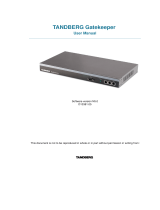
1.1 The TANDBERG 3G Gateway
Front view
The front panel provides 4 LAN interfaces, an LCD display, and an RS232 interface and control
buttons.
Rear view
The back panel provides four PRI interfaces, which can be activated individually by software
option keys, or 4 BRI interfaces depending on the configuration, one power switch/connector and
a VGA connector. Next to the PRI RJ-45 4 LED’s are mounted. In normal working condition the
green LED will be lit. Functions of the LED’s are:
Green: Normal operation
Red Alarm or Loss of signal (LOS) indicates that there is no signal and thus no framing info
received. A defect or unplugging the PRI cable will result in the same effect.
Yellow Alarm or Remote Alarm Indicator (RAI) means that the 3G Gateway is receiving framing
info, but in this framing info the other side tells the 3G Gateway that it is not reading the
gateway’s transmitted framing info. Typically, this may be a broken connector in the transmit (TX)
part of the PRI cable. This could also indicate weak or noisy signal in the transmit (TX) part of the
PRI cable.
10

TANDBERG 3G Gateway User Manual
Blue Alarm indicates that the received frames are not synchronized properly.
No LED’s light up, indicates that layer one framing is working (right protocol like for example
EURO ISDN selected), however there is a problem at layer 2 caused by for example a CRC4
configuration mismatch.
1.1.1 3G GATEWAY Capacity – typical scenarios
Due to the fixed bandwidth of UMTS video telephony every call will be limited to 64 Kbit. This
offers a capacity of 30 simultaneous calls through a single PRI 3G Gateway or 8 calls through a 4
x BRI 3G Gateway. Due to audio transcoding (AMR to G.711) the bandwidth at IP side is 109
Kbit/s per session, 64 Kbit G.711 audio and 45 Kbit H.263 video. Depending on the option
package and version of the 3G Gateway (PRI or BRI) the amount of simultaneous 3G calls can
be less then 30 or 23 for T1.
11

TANDBERG 3G Gateway User Manual
2 Installation
Precautions:
Never install telephone wiring during a lightning storm.
Never install telephone jacks in wet locations unless the jack is specifically designed for
wet locations.
Never touch uninstalled telephone wires or terminals unless the telephone line has been
disconnected at the network interface.
Use caution when installing or modifying telephone lines.
Avoid using a telephone (other than a cordless type) during an electrical storm. There
may be a remote risk of electrical shock from lightning.
Do not use the telephone to report a gas leak in the vicinity of the leak.
The socket outlet shall be installed near to the equipment and shall be easily accessible.
Never install cables without first switching the power OFF.
This product complies with directives: LVD 73/23/EC, EMC 89/366/EEC, R&TTE
99/5/EEC.
This product complies with the standards GR-63-CORE and GR-1089-CORE and is
NEBS approved by UL .For NEBS compliance, the product should be installed in the
following manner:
There should be a clearance of 9.1cm between the product and any other product
mounted in the rack.
12

TANDBERG 3G Gateway User Manual
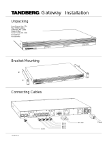
2.1 Unpacking
To avoid damage to the unit during transportation, the 3G Gateway is delivered in a special
shipping box, which should contain the following components:
User Manual and other documentation on CD.
Rack-ears, screws and screwdriver.
Cables:
o Power cable
o One to four ISDN PRI cables, depending on the number PRI Option keys, or 4
ISDN BRI cables depending on the version.
o Ethernet cable
o RS232 cable
TANDBERG 3G Gateway
Installation site preparations
Make sure that the 3G Gateway is accessible and that all cables can be easily
connected.
For ventilation: Leave a space of at least 10cm (4 inches) behind the 3G Gateway’s rear
panel and 10cm (4 inches) in front of the front panel.
The room in which you install the 3G Gateway should have an ambient temperature
between 0
º
C and 35
º
C (32
º
F and 95
º
F) and between 10% and 90% non-condensing
relative humidity.
Do not place heavy objects directly on top of the 3G Gateway.
Do not place hot objects directly on top, or directly beneath the 3G Gateway.
Use a grounded AC power outlet for the 3G Gateway.
You will need a CSU (Channel Service Unit) between your system and the PRI line from
your network provider.
Make sure that it is possible to receive and to make Mobile(h324M) video calls from
behind this line. Check this with your network operator!
If you are behind a PABX make sure that the PBABX is capable of routing Mobile
(H324M) video calls.
13

TANDBERG 3G Gateway User Manual
2.2 Connecting cables
Power cable
Connect the system power cable to an electrical distribution socket.
ISDN PRI or BRI cables
The E1/T1 cable should be connected to a CSU (Channel Service Unit). You will need a CSU
between your 3G Gateway and the PRI line from your network provider.
LAN cable
To use the 3G Gateway on IP, connect a LAN cable from the ‘LAN 1’ connector on the 3G
Gateway to your network. The LAN 2, 3 and 4’ connector is not used and should be left open.
RS 232 cable
To control the 3G Gateway using the data port, connect an RS 232 cable between the 3G
Gateway’s RS 232 connector and the COM-port on a PC. For further information, please refer to
the paragraph ‘
2.3’ and the Data Port Command Interface User Guide.
14

TANDBERG 3G Gateway User Manual
2.3 3G Gateway Configuration
The 3G Gateway requires some basic configurations before it can be used. It will be necessary to
find the IP-address and to create the dial-in and dial-out services program the ISDN-PRI Line
numbers.
It is possible to use the front panel LCD display or the serial RS232 cable. Using the RS232 cable
follow the instructions below:
1. Connect the RS232 cable between the 3G Gateway and a PC and then switch on the
3G Gateway.
2. Start a terminal program on the PC and configure it to: 115200, 8, 1, None.
3. a. To assign a static IP-address, type ‘Xconf ip Assigment: “Static” ’ and ‘Xconf Ip
address <IPAddr>’.
b. To assign an IP Subnetmask, type ‘Xconf ip address subnetmask <subnetmask>’.
c. To assign an IP Gateway address, type ‘Xconf ip address gateway <gateway IP-
address>’.
4. Restart the 3G Gateway.
5. Start a WEB browser and enter the IP-address of the 3G Gateway. Default password:
‘TANDBERG’.
6. To configure the 3G Gateway for UMTS dial in, enter PRI or BRI numbers and dial in
number(s). For details, see the ‘PRI Configuration’ and the ‘
Services Configuration’
section.
7. To configure the gateway for IP dial in, register the gateway to a gatekeeper and
enter H.323 services. For details, see chapter
5.10, Services Configuration..
The LCD panel makes it possible to configure and the Check the IP settings and to reboot the system. The
front panel LCD menu items are displayed below. Due to the limited amount of buttons the function will differ
on every menu level also depending on the function of the menu (reading or editing). Appendix 6.2 contains
a detailed description of every level and functions of every button. The usage of the buttons is designed in
an intuitive way and should not result in any problems.
MainMenu
IP settings
IP Information
Commands
IP Address
IP Netmask
IP Settings
IP Default GW
IP Address
IP Information
Reboot
Commands
To configure the IP number, follow the instructions below:
1. Press any key to get the main menu.
2. IP settings should be displayed.
3. Press [ENTER] to access the IP settings menu.
4. Us the [UP/DOWN] key to select IP Address.
5. Press [ENTER] to access the IP address editing menu.
15

TANDBERG 3G Gateway User Manual
6. Press [ENTER] again to get a cursor.
7. Use up down keys to navigate between the different digits.
8. After selecting a digit use the [ENTER] key in combination with the [UP/DOWN] key to change the
digit value.
9. When finished editing use [ESC] key to go to the confirm change menu.
10. Use the [UP/DOWN] key to select yes or no and [ENTER] to confirm.
11. Use [ESC] key to navigate back to the main menu.
Note that DHCP assigned IP-addresses are supported by the TANDBERG 3G Gateway (factory default),
3G Gateway start-up
To start the 3G Gateway, please make sure that the power cable is connected, and press the
power switch button at the back side to ‘1’.
On the front panel of the system the power indicator LED, marked ‘Pwr’, will turn GREEN.
Accessing the 3G Gateway
You may access the 3G Gateway by entering the IP-address of the 3G Gateway in a standard
WEB-browser. You will then be asked to enter a password. It is not necessary to enter ‘User
Name’. The default password for the 3G Gateway is ‘TANDBERG’. Remember that the password
is case sensitive. Note that it also possible to use SSH and Telnet to configure the 3G Gateway.
Note that the password can be changed in System Configuration’, Misc’. See also the section ‘5.8
Miscellaneous Configuration’.
Forgot the password? Use the following procedure to set a new password:
16

TANDBERG 3G Gateway User Manual
• Reboot the 3G Gateway.
• Connect to the 3G Gateway via the serial interface once it has restarted.
• Login with User Name pwrec. No password is required.
• One will be prompted for a new password.
The pwrec account is only active for one minute following a restart. Beyond that time the system will
have to be restarted again to change the password.
17

TANDBERG 3G Gateway User Manual
3 Using the 3G Gateway
3.1 Call Overview
The System Status windows of the Gateway can be accessed via the default URL:
http://3G_Gateway_IP_Address/.
The ‘Overview’ window presents information about all calls routed through the 3G Gateway, i.e.
inbound and outbound numbers, duration of the call and call status, like ringing (alerting),
connecting and connected.
GW Calls
Shows all active calls through the 3G Gateway.
[Idle] No call is active.
Active Call A call is active.
Source / Destination
18

TANDBERG 3G Gateway User Manual
Source shows the Status of the incoming call to the 3G Gateway, the number and which network
the incoming call is using.
Destination shows the Status of the outgoing call from the 3G Gateway, the number and which
network the outgoing call is using.
Idle No active call, call has been disconnected.
Alerting Call is being connected, i.e. ringing state.
Connected Call is connected.
Number ISDN or IP number.
IP/H.323 Call connected is using the H.323 protocol over IP.
Duration
Shows the length of the current call.
Status
Shows current status of the PRI and IP status.
PRI:
PRI line is synced and active. Click on More... to see status in detail.
PRI line is not active. Click on More... to see status in detail.
IP/H.323:
The gateway is registered with a Gatekeeper. Click on More... to see status in
detail.
The gateway is not registered with a Gatekeeper. Click on More... to see status in
detail.
Usage
The usage bar shows the current status of all the available resources (CPU, ISDN channels and
number of calls)
When the Resource Usage reaches the “Busy on Load”-limit, the gatekeeper will try to route
outgoing IP calls to other gateways. This is done to maintain availability for incoming UMTS calls
when using multiple gateways.
Resource Usage 90%. Click on the Usage link to see resource usage
in detail.
H.323 Busy on Load> 70%. Click on the Load link to adjust the value.
19

TANDBERG 3G Gateway User Manual
3.2 Dial from UMTS
The 3G Gateway supports three different UMTS Dial In services:
- “DiD” Æ Direct Inward dialing from a 3G handset.
- “IVR” Æ Dialing terminals from a 3G handset via a selection menu.
- “Phonebook” Æ Selecting an entry from a gateway phone book.
Any of these services can be enabled or disabled, but at least one must be enabled for incoming
call routing to take place.
In order to enable parallel incoming calls, a PRI number range must be defined.
For more details on UMTS Dial-In services, please see the section ‘5.10 Services’.
DID
Direct Inward Dialing (DID) will provide you with direct ISDN numbers for your IP endpoints i.e. it
will do a direct mapping between your ISDN number and an H.323/SIP Alias or vice versa. In
order to use DID you will need to have assigned multiple ISDN numbers to your ISDN PRI or BRI
line, as each ISDN number will map to a single IP endpoint.
Example:
Your ISDN number range is from 67124000 to 67124050 and DID is enabled.
You want your IP endpoints to have the numbers (H.323 Alias) in the range 94000 -
94050.
In the services Configuration, set (remove) Prefix/Nr to 67124, set Service Type to
DiD and (add) Prefix/Nr to 9.
To call an IP endpoint with H.323 Alias 94020 from ISDN, dial the ISDN number
67124020.
The gateway starts to call the IP endpoint and the “connecting” picture and sound are
activated.
When the call is connected audio and video are transmitted through the gateway.
IVR
Interactive Video Response (IVR), also called extension dial-in, is an automated answering
system that directs the call to the IP endpoint indicated by the caller. The caller uses telephone
tones (DTMF) to enter the H.323/SIP Alias or extension.
IVR is useful if you have limited numbers on your ISDN PRI or BRI line.
Example:
A videoconferencing system calls into the Extension Dial In number with IVR active.
The gateway activates the ‘Welcome’ picture and sound.
The videoconferencing system enters the extension (H.323 Alias) followed by the #
(pound-sign) to indicate end of number.
The gateway starts to call the IP endpoint and the “Connecting” picture and sound are
activated.
When the call is connected audio and video are transmitted through the gateway.
20
/