Page is loading ...

WORLD HEADQUARTERS & MANUFACTURING OPERATIONS
Highway 25E, P.O. Box
1060
Barbourville, KY
40906
888/800-JMSC
Fax: 606-523-9196
June 16, 1998 P/N 7610-011-44-01 Rev A

SECTION PAGE
WARRANTY POLICY INSIDE FRONT COVER
TABLE OF CONTENTS i
GENERAL
Machine Nomenclature
Important Safety Instructions
Nationwide Maintenance and Repair Centers
1
PARTS IDENTIFICATION AND FUNCTION
Diagram of Assembled Machine
2
INSTALLATION REQUIREMENTS
Electrical Requirements
Drain Hose Connection
Hot Water Supply Connection
Dishwasher Electrical Data Decal
Chemical Dispensing Equipment
6
DISHWASHER OPERATING INSTRUCTIONS
To Fill Dishwasher
To Drain the Machine
Manual Wash
8
TROUBLESHOOTING GUIDE 9
SERVICE PROCEDURES 14
ILLUSTRATED PARTS LIST 36
WIRING DIAGRAMS 60
NATIONWIDE MAINTENANCE AND REPAIR CENTERS (M&RC) INSIDE BACK COVER
i

Hot-water sanitizing Models JP-24/F and JP-24B/BF must have a minimum 180 Degree F. rinse water
temperature at a flow pressure of 20 PSI (+/-) 5 PSI to assure proper sanitization of ware.
The JP-24 series dishwasher is not supplied with chemical dispenser pumps for dispensing detergent,
rinse additive or sanitizer (JP-24LT/F). Consult your local detergent representative for information about a
chemical dispenser.
Low-temperature chemical sanitizing Model JP-24LT/LTF requires a minimum of 50 PPM of 5.25 %
sodium hypochlorite (liquid bleach) be injected in the final rinse line during the rinse. Do not operate
dishwasher as a low-temperature chemical sanitizing machine without a properly installed, N.S.F.
recognized chemical dispenser.
The "B" designation in the model number indicates the unit has a built-in hot water booster tank, requiring
a 140 Degree F. hot water supply. Units without the "B" require a 180 Degree F. hot water supply. The
"LT" designation indicates a low-temperature model requiring a minimum 120 Degree F. and 140 Degree
F. maximum hot water supply.
Free standing units not installed under a counter top will require a top and side panels, indicated by a "F"
designation in the model number.
IMPORTANT SAFETY INSTRUCTIONS
Please read all instructions before using this dishwasher. Safety precautions in this manual are preceded
by the words "DANGER", "WARNING", "CAUTION", or "NOTE" and are very important. DANGER is used
to indicate the presence of a hazard which will cause severe personal injury, death or substantial property
damage if the statement is ignored. WARNING is used to indicate the presence of a hazard which can
cause severe personal injury, death or substantial property damage if the statement is ignored. CAUTION
is used to indicate the presence of a hazard which will or can cause minor personal injury or property
damage if the statement is ignored. NOTE is used to notify personnel of installation, operations, or
maintenance information which is important, but not hazard related.
NATIONWIDE MAINTENANCE AND REPAIR CENTERS
If repairs or replacement parts are required, please call one of the Jackson Authorized Maintenance & Repair
Centers from the list provided on the rear cover of this manual. An illustrated list of replacement parts are included in
this manual to assist in identification and ordering of parts. BE SURE THAT ALL REPLACEMENT PARTS
PURCHASED AND USED IN YOUR DISHWASHER ARE GENUINE ORIGINAL PARTS, DISTRIBUTED BY A
JACKSON MAINTENANCE & REPAIR CENTER LISTED IN THE REAR COVER OF THIS MANUAL.
UNAUTHORIZED SUBSTITUTIONS MAY RESULT IN FIRE, ELECTRIC SHOCK OR OTHER HAZARDS.
1

PARTS IDENTIFICATION AND FUNCTION
ITEM
DESCRIPTION FUNCTION
1. Top Enclosure Panel Encloses Top - Freestanding Units
2. Right Side Panel Encloses Right Side of Machine
3.
Door Switch (Not Shown)
Starts Dishwashing Cycle
4.
Door Frame Panel
Access Pane
l to Door Switch/Spring
5.
Electrical Data Decal
Dishwasher Electrical Requirements/Serial No.
6. Electrical Control Panel Gauges/Switches for Operation
7.
Kick Panel
Encloses Electrical Panel Area
8. Dishwasher Door Encloses Dishwashing Area
9. Operating Instruction Decal Operating Procedures
10.
Left Side Panel Not Shown)
Encloses Left Side of Machine
11.
Door Handle
Used to Open and Close Door
12. Upper Rinse Arm & Feed Pipe Sprays Rinse Water Over Ware
13.
Right Rack Slide
Holds Rack Above
Spray Arms
14. Right Frame Leg Supports Right Side of Machine
15.
Leveling Foot
Used to Level Machine
16.
Lower Rinse Arm
&
Feed Pipe
Sprays Rinse Water Over Ware
17. Wash Spray Arm Sprays Wash Tank Water Over Ware
18.
Line Strainer
-
(1/2")
Filters
Debris From Water Supply Line
19. Pet Cock Valve Tap for Checking Rinse PSI/Temp.
20. Fill Solenoid Valve Allows Water in During Rinse/Fill
21.
Rinse Booster Tank (JP
-
24B/BF)
Holds Rinse Water For Heating
22.
Booster Tank Heater
(JP
-
24B/BF)
Heats Boo
ster Water For Rinse
•23.
Basket Strainer
Catches Food Soil in Wash Water
24. Left Rack Slide Holds Rack above Spray Arm
25.
Vacuum Breaker
(1/2")
Prevents Backflow into Water Supply
26. Rinse Injection Manifold Rinse Chemical/Sanitizer (JP-24LT/LTF) Injected
27.
Rinse Thermometer Bulb
Reads Final Rinse Temperature When Rinsing
28.
Vacuum Breaker Feed Pipe
Final Rinse Water Supplied Via Pipe
29. Detergent Injection Plug Injection Point for Detergent
30.
Rinse Thermometer Capillary
Senses Tempera
ture in Rinse Line
31, Rinse Booster Tank (JP-24B/BF) Heats Water for Final Rinse
32.
Drain Valve
(1
10V or 220V)
A
llows Waste Water to Drain Out
33. Hose, Pump to Drain Valve Carries Waste Water to Drain Valve
34.
Pump
&
Motor Assembly
Recirculates W
ash Water
35. Fill Line to Dishwasher Supplies Water to Dishwasher
36.
Fill Solenoid Valve
(1
10V or 220V)
Opens Water Supply Line
37. Petcock Valve Used to Check Pressure/Temp.
38.
Fill Line Strainer
(1/2")
Filters Water Supply Line
39.
Drain Hose
Fee
ds Waste Water to Drain System
40.
Rinse Manifold
Feeds Water From Booster to Rinse Arms
41. Hose, Rinse to Injection Feeds Rinse Water to Manifold
2

PARTS ID & FUNCTION
3

PARTS ID & FUNCTION
4

PARTS ID & FUNCTION
5

INSTALLATION REQUIREMENTS
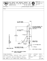
MODEL JP.24B/BF-ELECTRICAL REQUIREMENTS - SEE FIGURE - 1
IMPORTANT - PLEASE READ CAREFULLY - THE RINSE HEATER RELAY HAS BEEN TEMPORARILY
DISABLED SO THAT THE MACHINE'S INTERNAL BOOSTER TANK CAN FILL WITH WATER BEFORE
TURNING ON THE HEATING ELEMENT. A QUALIFIED SERVICEMAN MUST RECONNECT THE WIRE
(ORANGE/WHITE) TO THE RINSE HEATER RELAY COIL (TAGGED) AFTER THREE CYCLES OF OPERATION
AND THE WASH TANK IS FULL OF WATER. THE CIRCUIT BREAKER FEEDING THE UNIT SHOULD BE
TURNED OFF BEFORE DOING THIS.
DRAIN HOSE CONNECTION
Dishwasher has a pumped (pressure) drain capable of pumping waste water to a height of 24 inches from
floor to the kitchen's drain system. The dishwasher is supplied with a 8-foot long drain hose that extends
from the right rear side of machine. Drain hose must be installed indirect to kitchen's drain system with air
gap. It protects the dishwasher against water backing up in it if a drain clogs.
6

INSTALLATION REQUIREMENTS continued
HOT WATER SUPPLY CONNECTION
Install the water supply line (1/2" pipe size minimum) to the dishwasher line strainer using a soft copper
tube, flexible tube or hose to allow machine to be moved for servicing.
DISHWASHER ELECTRICAL DATA DECAL
DISHWASHER ELECTRICAL DATA DECAL is located on the right-side of unit at front. Refer to the
electrical data decal for machine operating requirements, machine voltage/total amperage load, and serial
number.
CHEMICAL DISPENSING EQUIPMENT
The JP-24 series dishwasher is not supplied with dispenser pumps for detergent, rinse additive or sanitizer
(JP-24LT/F). An injection hole is provided in the back wall of machine for dispensing detergent into
dishwasher wash tank. An injection manifold is provided in the final rinse line for injecting rinse additive and
sanitizer (Model JP-24LT/F requires a minimum of 50 PPM of 5.25% sodium hypochlorite (liquid bleach) be
injected in the final rinse line during the rinse).
Electrical power and signal source for detergent, rinse additive and sanitizer (JP-24LT/F) dispensing
equipment are available as follows:
DETERGENT SIGNAL - White/Red wire, "L1" signal (line voltage) for detergent dispensing. Detergent
dispenses during rinse cycle.
DISPENSER POWER - Red wire, "L2" return (line voltage). DISPENSER MAXIMUM AMPERAGE LOAD:
FUSE-TYPE 3AG "SLO-BLO", 2.5 MAXIMUM.
DISPENSER POWER - Green/White wire, "L1" power (line voltage) during dishwashing cycle. RINSE
AGENT/SANITIZER - Blue wire, "L1" signal (line voltage) (parallel with rinse/fill solenoid).
7

DISHWASHER OPERATING
INSTRUCTIONS
DISHWASHING CYCLE: Once the machine is initially filled, the dishwashing cycle consists of: the
machine washes a rack of dishes, drains the wash water, and then rinses with fresh water which remains
in the machine to wash the next rack of dishes. During the rinse, detergent, rinse additive, and sanitizer
(JP-24LT/LTF) should be injected.
TO FILL THE DISHWASHER
1. Close door and depress Power Switch to On/Fill position and place Cycle Switch to Auto position.
Red power indicator light will light to indicate machine has power turned on and the green light
will come to indicate that machine is automatically filling with water. Proper water level will be
achieved when water touches the bottom of pan strainer.
NOTE: CYCLE SWITCH MUST BE IN THE AUTO POSITION TO FILL MACHINE. MACHINE WILL NOT FILL
IN THE MANUAL POSITION AND WOULD CAUSE PUMP MOTOR TO RUN WITHOUT WATER
WHICH CAN DAMAGE PUMP SEAL.
2. After the wash tank is full of water, the green fill light will go out. Open the door, the amber cycle light
will go out to indicate that the machine is reset for another dishwashing cycle.
3. Placing the Cycle Switch to the center "off" position will allow the door to be opened and closed
without starting an automatic cycle.
4. If door is opened during a dishwashing cycle, machine will stop the cycle until door is closed. When
door is closed, cycle will resume where it was stopped.
TO DRAIN THE MACHINE AT END OF DAY/MEALTIME
5. The dishwasher cycle switch must be in the Auto position in order to drain machine. Machine will not
drain in the Manual mode.
6. Close the door and start a dishwashing cycle without a rack in the machine.
7. Once the cycle has started and the amber cycle light is on, push the Power Switch from the On/Fill
position to the Off/Drain position. The machine will finish the wash cycle and then drain.
MANUAL WASH
8. Place Cycle Switch in the Manual Wash position. In this position, machine will wash indefinitely until
switch in placed in center Off or Auto Cycle position.
8

TROUBLESHOOTING GUIDE
The following Troubleshooting Guide contains a list of possible problems/faults/symptoms which can be
used as a quick-reference to solving problems. Refer to appropriate section identify the equipment
malfunction.
WARNING: INSPECTION, TESTING AND REPAIR OR ELECTRICAL EQUIPMENT SHOULD BE PERFORMED
ONLY BY QUALIFIED SERVICE PERSONNEL. CERTAIN PROCEDURES IN THIS MANUAL REQUIRE ELEC-
TRICAL TESTS OR MEASUREMENTS WHILE POWER IS APPLIED TO THE DISHWASHER. EXERCISE
EXTREME CAUTION AT ALL TIMES. IF TEST POINTS ARE NOT EASILY ACCESSIBLE. DISCONNECT POWER
AND ATTACH TEST EQUIPMENT AND REAPPLY POWER TO TEST. DISCONNECT THE ELECTRICAL POWER
TO THE DISHWASHER AT THE MAIN CIRCUIT BREAKER BOX WHEN SERVICING. PLACE A TAG ON THE
CIRCUIT BOX INDICATING THE CIRCUIT IS BEING REPAIRED.
ITEM
PROBLEM
1. NOTHING ON MACHINE OPERATES (POWER SWITCH ON)
2. WILL NOT FILL AUTOMATICALLY (POWER SWITCH ON)
3. MACHINE WILL NOT RUN IN AUTO (POWER SWITCH ON)
4. MACHINE RUNS IN AUTOMATIC BUT MANUAL FUNCTION DOES NOT WORK
5. WASH TEMPERATURE LOWER THAN REQUIRED 150 DEG. F.
6. RINSE TEMPERATURE LOWER THAN REQUIRED 180 DEG. F.
7. FILLS SLOWLY AND/OR RINSE IS WEAK
8. RINSE WATER RUNS CONTINUOUSLY (POWER IS ON)
9. RINSE WATER RUNS CONTINUOUSLY (POWER IS OFF)
10. WASH TANK WATER LEVEL IS LOW
11. WASH TANK WATER LEVEL IS HIGH
12. DISHES ARE NOT COMING CLEAN
13. GLASSES AND SILVERWARE ARE SPOTTING
14. DOOR DROPS HARD AND WON'T STAY CLOSED
15. DOOR DOESN'T ACTIVATE CYCLE
16. WASH PUMP LEAKS
17. WON'T RINSE DURING CYCLE
18. VERY HIGH RINSE TEMPERATURE
19. VERY HIGH WASH TEMPERATURE
20. VACUUM BREAKER LEAKS
21. WATER FLOODING FROM DISHWASHER
22. WATER COMING OUT FROM BOTTOM OR SIDES OF DOOR WHEN CLOSED
9

TROUBLESHOOTING GUIDE continued
ITEM PROBLEM
1. NOTHING ON MACHINE OPERATES "POWER SWITCH ON - POWER LIGHT OFF"
1. Dishwasher circuit breaker turned off.
2. Defective circuit breaker - have electrician test.
3. Circuit breaker tripped - overload in circuit. a. Have electrician check amperage on
circuit.
2. WILL NOT FILL AUTOMATICALLY "POWER SWITCH ON - POWER LIGHT ON- RINSE/FILL
LIGHT OFF"
1. Close door completely and try again.
2. Faulty On/Fill - Off/Drain Switch.
3. Faulty Timer Cam Switch C-5.
4. Faulty Timer Cam Switch C-2.
5. Faulty Timer Motor.
6. Loose terminal connection or broken wire in circuit.
3. WILL NOT FILL AUTOMATICALLY "POWER SWITCH ON - POWER LIGHT ON -RINSE/FILL
LIGHT ON"
1. Low water supply pressure (requires 15-25 PSI flow) to machine
2. Faulty rinse/fill solenoid.
4. MACHINE WILL NOT RUN WASH/DRAIN/RINSE CYCLE IN AUTO CYCLE MODE BUT WILL
RUN WASH CYCLE IN MANUAL CYCLE - POWER SWITCH "ON" - POWER LIGHT "ON" -
CYCLE LIGHT-ON" IN AUTO
1. Faulty timer motor or bad connection.
2. Faulty timer motor cam switches C-3, C-4, C-5.
5. MACHINE WILL NOT RUN WASH/DRAIN/RINSE CYCLE IN AUTO CYCLE MODE BUT WILL
RUN WASH CYCLE IN MANUAL CYCLE - POWER SWITCH "ON" - POWER LIGHT "ON" -
CYCLE LIGHT "OFF" IN AUTO
1. Faulty timer motor or bad connection.
2. Faulty auto/manual switch.
3. Faulty timer cam switch C-3.
4. Faulty power switch S-1.
5. Faulty timer cam C-1.
6. Open circuit between door switch S-2 normally closed (N.C.) contacts
(Black/White wire) output and timer cam switch C-1 normally closed
(N.C.) contacts.
6. MACHINE RUNS DISHWASHING CYCLE IN AUTOMATIC BUT MANUAL WASH FUNCTION
DOES NOT WORK - POWER SWITCH "ON" - POWER LIGHT "ON" - CYCLE SWITCH IN
"MANUAL WASH".
1. Faulty cycle switch.
10

TROUBLESHOOTING GUIDE continued
ITEM PROBLEM
7. WASH TEMPERATURE LOWER THAN REQUIRED 150 DEG. F.
1. Faulty temperature gauge.
2. Rinse temperature below 180 cleg. F. minimum.
See RINSE TEMPERATURE LOWER THAN REQUIRED 180 DEG. F.
8. RINSE TEMPERATURE LOWER THAN REQUIRED 180 DEG. F.
1. Faulty temperature gauge.
2. Faulty rinse booster tank thermostat or adjustment.
3. Incoming water supply pressure not 15-25 PSI flow pressure.
4. Incoming water supply temperature below 140 deg. F. min.
5. Faulty power switch.
6. Faulty rinse booster tank heater element.
7. Rinse booster tank heater element scaled by hard water.
8. Faulty rinse booster heater contactor.
9. FILLS SLOWLY AND/OR RINSE IS WEAK
1. Low water pressure to dishwasher.
2. Rinse spray arms clogged or limed up.
10. RINSE WATER RUNS CONSTANTLY - "POWER IS ON" - "RINSE/FILL LIGHT ON" - RINSE STOPS
& LIGHT GOES OUT WHEN POWER IS TURNED OFF
1. Faulty timer switch cam C-5.
11. RINSE WATER RUNS CONSTANTLY - "POWER IS OFF" - "RINSE FILL LIGHT OFF
1. Check for excessive pressure to machine. Operating pressure is 15 -
25 PSI flow pressure.
2. Faulty rinse/fill solenoid.
12. WASH TANK WATER LEVEL IS LOW
1. Check for proper flow pressure to machine.
2 Check for minimum 1/2 pipe water supply line.
3. Check for clogged rinse spray arms.
4 Faulty timer cam switch C-5 for rinse/fill. Cycle not long enough
5. Faulty timer cam switch C-4 for draining. Cycle too long- may need calibration.
6. Leaking drain valve seal - see service procedures for replacement.
13. WASH TANK WATER LEVEL IS HIGH
1. Check for proper flow pressure to machine.
2. Faulty timer cam switch C-5 for rinse/fill. Cycle too long - may need calibration.
3. Faulty timer cam switch C-4 for draining. Cycle not long enough - may need calibration.
4. Faulty drain valve.
11

TROUBLESHOOTING GUIDE continued
ITEM PROBLEM
14. DISHES ARE NOT COMING CLEAN
1. Check water flow pressure to dishwasher.
2. Wash/rinse arms not rotating properly/clogged.
3 No detergent or improper concentration.
4. Dishwashing cycle times, wash, drain and rinse not correct.
5. Not pre-rinsing and pre-scrapping ware.
6. Wash and rinse water temperatures not correct.
7. Leaking drain valve seal.
15. GLASSES AND SILVERWARE ARE SPOTTING
1. Hard water condition.
2. Not using wetting agent.
3. Check water flow pressure to dishwasher.
4. Rinse spray arms not rotating properly/clogged.
5. Detergent concentration very high.
16. DOOR DROPS HARD AND WON'T STAY CLOSED
1. Broken door spring.
2. Bent hinges.
17. DOOR DOESN'T ACTIVATE CYCLE
1. Door switch needs and adjustment.
2. Defective door switch.
3. Timer not reset.
4. Faulty timer motor.
5. Faulty Cycle switch.
6. Faulty time cam switch C-1.
18. WASH PUMP LEAKS
1. Petcock valve open on pump.
2. Pump shaft seal defective.
3. Defective hose.
4. Defective pump gasket.
19. WONT RINSE DURING CYCLE
1. Power Switch depressed to Off/Drain position
2. Water supply turned off.
3. Defective timer cam switch C-5.
4. Defective fill solenoid.
12

TROUBLESHOOTING GUIDE continued
ITEM PROBLEM
20. VERY HIGH WASH OR RINSE TEMPERATURE
1. Faulty thermostat.
2. Rinse heater relay contacts sticking.
21. VACUUM BREAKER LEAKS
1. Very low water supply pressure.
2. Rinse arms clogged.
3. Vacuum breaker internal parts defective.
22. WATER FLOODING FROM DISHWASHER
1. Blocked drain line.
2. Defective drain valve.
3. High water supply pressure.
4. Defective water solenoid.
5. Faulty timer cam C-4.
13

SERVICE PROCEDURES
WARNING: INSPECTION, TESTING AND REPAIR OF ELECTRICAL EQUIPMENT SHOULD BE PERFORMED
ONLY BY QUALIFIED SERVICE PERSONNEL. CERTAIN PROCEDURES IN THIS MANUAL REQUIRE
ELECTRICAL TESTS OR MEASUREMENTS WHILE POWER IS APPLIED TO THE DISHWASHER. EXERCISE
EXTREME CAUTION AT ALL TIMES. IF TEST POINTS ARE NOT EASILY ACCESSIBLE, DISCONNECT POWER
AND ATTACH TEST EQUIPMENT AND REAPPLY POWER TO TEST. DISCONNECT THE ELECTRICAL POWER
TO THE DISHWASHER AT THE MAIN CIRCUIT BREAKER BOX WHEN SERVICING. PLACE A TAG ON THE
CIRCUIT BOX INDICATING THE CIRCUIT IS BEING REPAIRED.
The following is a list of service procedures included in this manual:
1. To replace Drain Valve assembly, Valve Motor
Valve Seal, Hoses and to check for leaking drain valve
Page 15
2. To replace rinse/fill solenoid valve coil or internal parts Page 17
3. To replace Pump Motor Assy., Pump Seal, Capacitor, Impeller Page 18
4. Timer adjustment, replacing; Timer, Cam Switch, Motor Page 20
5. To replace Door Switch, adjustment/check Page 23
6. To replace or check Power & Off Drain Switch Page 24
7. To replace or check Cycle Switch Page 25
8. To replace or test Booster Tank Heater Page 25
9. To replace or adjust Booster Heater Thermostat Page 25
10. To replace Booster Tank - Model JP-24B/BF Page 27
11. To install Vacuum Breaker repair kit Page 29
12. To replace the Wash or Rinse temperature gauges Page 30
13. To replace Rinse Spray Arm feed pipe or internal parts Page 32
14. To replace Wash Spray Arm internal parts Page 32
15. To adjust Rack Slides or replace broken mounting stud Page 33
16. To check Water Supply Pressure to Dishwasher Page 33
17. To check Water Supply Temperature Page 34
18 To clean Water Line Strainer Page 34
19. To replace the Door Springs Page 34
20. To replace Door Latch Assembly Page 35
14

SERVICE PROCEDURES continued
1. To replace Drain Valve, Valve Seal, Hoses.
The motor operated drain valve is electrically operated by the timer during the drain cycle. It is also activated
when the machine is placed in the off-drain position. The motor operated drain valve diverts the main pump
water flow through valve and out drain hose to kitchen's waste system. It is a spring-loaded normally closed
valve. There are two valves available, 240V and 110V, (JP-24LT/LTF) each have identical parts except
motor. See illustrated parts list for correct valve. —
A. To remove the drain valve or drain valve hoses for servicing:
(1) Turn off the water supply to the dishwasher.
(2) Move machine away from wall for servicing.
(3) Remove lower enclosure panel at rear of machine.
(4) Drain the dishwasher. Siphon out water or remove inlet hose to drain valve and drain into pan.
Machine may be drained by opening petcock on pump housing or by removing wash thermometer
bulb from lower wash tank fitting.
B. To replace feed hose to drain valve from pump.
(5) Loosen hose clamps and remove inlet hose. Reverse procedures to install new hose.
15

SERVICE PROCEDURES continued
C. To replace drain valve.
(6) Disconnect the lead wires and ground to drain valve. Remove discharge hose from valve.
(7) Remove drain valve from mounting place.
(8) Reverse procedures to install new valve. INSURE GROUND WIRE LEAD IS CONNECTED
PROPERLY TO TERMINAL ON MOTOR.
D. To check for leaking drain valve.
(1) Open door and verify water level in wash tank is up to basket strainer screen.
(2) Close door and start dishwashing cycle.
(3) Wait (30) seconds and open door (slowly).
(4) Check water level in wash tank if it is lower than before - the drain valve seal is leaking. See
service procedures to replace valve seal.
E. To replace drain valve seal.
(1) Follow procedures (1-8) above except don't remove inlet or discharge hoses.
(2) Remove cover plate from end of valve which is secured by (4) screws. Be careful not to damage
gasket.
(3) Remove stainless steel hinge with seal attached. See Illustrated Replacement Parts for exploded
view of parts.
(4) Install replacement hinge with seal and reassemble valve in reverse order.
F. To replace drain valve motor.
(1) Follow procedures (1-8) above.
(2) Remove motor from drain valve assembly which is secured by (4) screws. Note: Make note of
orientation of coil spring for proper reassembling of valve. See illustrated parts for exploded
view.
(3) Install replacement motor and reassemble valve in reverse order.
(4) Reinstall drain valve to machine in reverse order of above.
16

SERVICE PROCEDURES continued
2. To replace rinse/fill solenoid valve coil or internal parts.
The rinse/fill solenoid valve is electrically operated by the cam timer at the initial fill (at start of day/meal)
and then during the rinse cycle. Most problems are coil failures or water deposit buildup on diaphragm. See
illustrated parts list for repair parts.
A. To replace solenoid valve coil.
(1) Disconnect power to machine.
(2) Disconnect wire leads to coil.
(3) Remove screw holding coil in place and
remove coil.
(4) Install new coil in reverse order.
B. To replace Solenoid Valve internal parts.
(1) Shut off water supply to machine.
(2) Take valve apart as shown by unscrewing
the bonnet from valve body. Carefully lift off
the bonnet. The "o" ring seal and
diaphragm can now be lifted out. Don't drop
the plunger.
(3) Most problems are with a clogged
diaphragm pilot port. Clear pilot port in
diaphragm.
(4) To reassemble valve place the diaphragm
cartridge in the body with the pilot port
extension UP.
Hold the plunger with the synthetic seat
against the pilot port. Make sure the "o" ring
is in place, then lower the bonnet and
enclosing assembly over the plunger. Screw
the bonnet assembly firmly down on the
body.
(5) Turn on water supply to machine.
17

SERVICE PROCEDURES continued
3. To replace the pump motor assembly, pump seal, capacitor or impeller
Capacitor Start, Built-in Overload Protection. Marathon Jet Pump Assembly, 3450 RPM, 3/4 HP, 60 HZ, 1 PH,
115V/230V, FLA 8.8/4.4 AMPS, SPA 10.6/5.3 AMPS, ROTATION - CLOCKWISE. Mechanical Shaft Seal -
Standard Self-adjusting Shaft Seal (EPT Mechanical Seal) White Ceramic Seat and Carbon Seal Face.
Permanently Lubricated Ball Bearings. Direction o rotation should match the molded arrow on the pump
housing.
Motor has a capacitor start circuit controlled by a centrifugal switch. Once the start windings in the motor
have rotated the rotor to the proper running speed/rpm, the centrifugal switch opens and drops out the
capacitor. The main windings will then keep the motor running at run rpm.
Most problems can be found in either the capacitor or centrifugal switch.
A. To check the capacitor with an ohmmeter or substitute with good capacitor. WARNING:
Discharge capacitor before testing with ohmmeter.
Steps:
(1) Disconnect power to dishwasher and unplug wire leads from capacitor. Use appropriate range
on ohmmeter.
(2) If the capacitor is good, the meter should go to the right and then decrease slowly.
(3) If the capacitor is shorted, the meter should go to the right and stay there.
(4) If the capacitor is open, the meter should not read anything.
B. To replace the pump motor assembly.
/