Page is loading ...

MODEL 24LT
LOW-TEMPERATURE CHEMICAL SANTIZING
UNDERCOUNTER DISHWASHER
INSTALLATION/ OPERATION MANUAL
INCLUDES:
801 AIRPARK CENTER DRIVE
NASHVILLE, TN (615)399-3944 1-
800-736-8144 FAX (615)-366-
9126
April 4,1997 7610-100-38-00 Rev A
-Warranty Policy
-Installation Requirements
-Operating Instructions
-Description of Components
-Basic Functions of Dishwasher
-Maintenance and Care
-Illustrated Parts List
-Wiring Diagram

TABLE OF CONTENTS
BEFORE CONNECTING, OPERATING OR ADJUSTING THIS PRODUCT, PLEASE READ THIS
INSTRUCTION MANUAL CAREFULLY AND COMPLETELY.
FOR YOUR CONVENIENCE, THIS MANUAL CONSISTS OF THE FOLLOWING SECTIONS IN
THIS ORDER:
1. INSTALLATION
2. OPERATION
3. SPECIFICATIONS
4. CARE AND CLEANING
5. TROUBLESHOOTING
6. ILLUSTRATED PARTS LIST
7. WARRANTY

GENERAL
SAFETY PRECAUTIONS
Never try to repair or replace any part of the dishwasher unless it is specifically recommended
in this manual. All servicing should be done by a factory authorized service technician during
warranty period, there are no user serviceable parts. Safety precautions in this manual are
preceded by the words warning or caution and are very important. Warning means there is the
possibility of personal injury to yourself or others. Caution means there is the possibility
of damage to the unit.
CERTIFICATION
The UL Mark on this product Listed with
the Underwriters conducts tests and
evaluations to UL Standards for Safety.
indicates this product is I
Laboratory. This agency of
products for compliance
The NSF Seal is widely recognized as a sign that the article to which it
is affixed complies with all public health and safety codes for
foodservice equipment.
PRODUCT RECORD
For future use, please record the information in the spaces provided below.
MODEL NUMBER_______________________________
SERIAL NUMBER______________________________
DATE INSTALLED_____________________________
DEALER_____________________________________

hrINSTALLATION
GENERAL
The Model 24LT Low-Temperature Chemical Sanitizing Dishmachine requires 50 Parts Per Million of Chlorine be dispensed
into the final rinse water for proper sanitizing of the ware.
Installation of the Sanitizer, Detergent and Rinse Dispensing equipment connections must be made to back of machine before
installing dishmachine undercounter or where installation will prevent access to back of machine.
Dishmachines not installed undercounter must be leveled. Adjust machine level by screwing the (feet) levelers in or out to raise
or lower corners of machine. Level back and front, then left and right sides of machine.
Refer to the Specification section of this manual for all Dimensional requirements for installation
COMPLETE THE INSTALLATION CHECKLIST AFTER INSTALLATION IS COMPLETED
PLUMBING CONNECTIONS
All Plumbing connections must comply with all Sanitary, Safety and Plumbing Codes.
CAUTION: Flush hot water supply lines prior to connection to dishmachine to remove all debris
from lines.
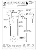
STEPS : REFER TO FIGURE [1] Next Page
1- Install a 1/2" (MIN.) supply line to the dishmachine
hot water incoming 1/2" NPT Female fitting as shown in Figure [1].
Manufacturer recommends using a flexible copper 1/2" supply line with
sufficient length looped at rear of dishmachine to allow machine to be
removed for servicing.
NOTE: Supply line must have capacity to supply 43.7 gallons per hour
of 120 F.(MIN.) of hot water at 20 PSI Flow pressure. Manufacturer
recommends 140 F. hot water for best results.
NOTE: If water flow pressure is greater than 20 PSI, install a pressure
regulator and adjust to 20 PSI Flow pressure. If flow pressure is less
than 20 PSI, an adjustment must be made to the machine's Timer to
increase the Fill cycle time during the Fill cycle so machine can fill to
it's proper water level. See Timer Adjustment.


INSTALLATION
DRAIN CONNECTION
The Dishmachine is factory equipped with a Pump Drain system capable of pumping the drain
water to a height of 24 inches from the floor. Approximately six (6) feet of drain hose is
provided and attached to rear of machine. A hose barb and clamp are also provided along with a
1-1/2" PVC Threaded Adaptor for convenient installation to nearest dishwasher "Y".
CAUTION: Drain hose is factory mounted to rear of dishmachine at MAXIMUM height of
(24") at which drain water can be pumped. DO NOT remove or relocate hose
to higher level from which it is factory located. Do not elevate hose
higher from this level of machine.
STEPS : REFER TO FIGURE [1]
1. Install the 1-1/2" PVC threaded adaptor into dishmachine "Y" using teflon
pipe tape as shown in Figure [1].
2. Install the threaded hose barb provided into adaptor.
3. Cut dishmachine drain hose to appropriate length to reach the hose barb and
install to barb using the hose clam? provided.
NOTE: Leave sufficient length of hose at back of machine to allow machine to
be moved forward for servicing.
PROCEED TO ELECTRICAL CONNECTIONS

INSTALLATION
ELECTRICAL CONNECTION
WARNING: All wiring connections must conform to the local and national electrical codes.
Refer to machine electrical data plate located on front of machine and Specification section of
this manual for proper electrical ratings.
POWER CORD
The dishmachine is provided with six (6) feet of power cord so connection can be made
to nearest receptacle. Do not alter or remove this power cord in any manner.
STEPS :
1. Plug machine's power cord into convenient wall receptacle nearest machine
which has service breaker rated for the machine's total load amperes.
WARNING: Wall receptacle to which machine's power cord is connected MUST have
proper electrical ground. Test for proper electrical grounding.
UNDERCOUNTER INSTALLATION
Dishmachines installed undercounter without feet (adjustable levelers) must be sealed to floor
by using sealer such as RTV, SILICONE or other non-toxic sealers.
STEPS
1. Once machine is in permanent position, seal base of machine to floor
with sealer along edges of sides.
PAN STRAINER
Install Pan Strainer provided into wash/rinse tank. SPRAY ARMS
Install upper and lower spray arms by inserting spindle end of arm into hub and turn clockwise
while applying pressure.
PROCEED TO CHEMICAL DISPENSING EQUIPMENT

INSTALLATION
CHEMICAL DISPENSING EQUIPMENT
The Model 24LT is equipped with a factory installed Sanitizer pump for accurately dispensing
sanitizer into the final fresh water rinse. A Detergent and Rinse pump dispenser is not
provided with this dishrnachine and must be installed prior to undercounter installation. An
electrical connection point and signal is provided for the installation of a Detergent and
Rinse dispensing pump. Refer to the following instructions for proper installation of
this equipment.
SANITIZER DISPENSING
STEPS:
1. Install the Sanitizer "WHITE" plastic suction tube end and the Sanitizer
"CLEAR" plastic probe tube end into the sanitizer container bottle so both
tube ends touch bottom of bottle. Tubes are located at rear of machine and
must be routed to bottle in such a manner as not to crimp or bend sharply.
NOTE: The clear plastic probe tube installed above is used to constantly
measure sanitizer solution level in bottle. When solution level in bottle
drops below two (2) inches, an indicator light located in the prime switch
will light up to provide a signal to the operator that the sanitizer bottle
is low.
PRIME SWITCH
The sanitizer priming switch is located on the control panel. This prime switch will only
activate the factory installed sanitizer pump, so priming of the sanitizer line to the
injection point can be accomplished. The sanitizer injection fitting is located
inside of dishrnachine, directly above pan strainer at rear wall.
S T E P S:
Press prime switch while observing the injection fitting inside of machine
and release switch when solution is primed.
PROCEED TO SANITIZER DISPENSING ADJUSTMENT

INSTALLATION
SANITIZER DISPENSING ADJUSTMENT
The sanitizer dispenser pump is factory pre-set to accurately dispense approximately 7.5
milliliters (50 parts per million) sanitizing agent based on an 8.4 % solution of Sodium
Hypochlorite.
Adjustment of the sanitizer dispenser pump timer may be necessary depending on the type and
sanitizer solution used. Consult your chemical representative for further details. Refer to
Timer Adjustment section of this manual for proper adjustment of sanitizer dispensing.
DETERGENT AND RINSE AGENT DISPENSING EQUIPMENT
The Model 2 ALT is a Dump-and-Fill type dishmachine which dumps the wash tank water and
refills with fresh water each cycle. This type of dishmachine cannot use the concentration
probe often used in the wash tank to control detergent injection.
The dishmachine will supply an electrical signal of 115 volts during the wash and rinse cycle
for detergent and rinse agent equipment connection. The duration of this signal can be
increased or decreased to achieve proper solution in wash/rinse water. Refer to Timer
Adjustment section of this manual for proper procedures for increasing or decreasing
detergent and rinse agent dispensing duration.
NOTE: The Detergent dispensing timer is factory set to dispense approximately 12
milliliters of detergent during the wash cycle. The Rinse agent dispensing timer is
factory set to dispense approximately. 5 milliliters of rinse additive during the rinse
cycle.
STEPS : DISCONNECT POWER TO MACHINE
1. Remove and discard the plastic bulkhead plug provided for installation of
detergent and/or rinse injection fitting at back of machine.
2. Install detergent and/or rinse injection fitting into 7/3" diameter hole
provided.
3. Remove front lower kick panel from dishmachine to access electrical
connection point for dispensing equipment. Dishmachine door must be
opened slightly for upward removal of lower kick panel.
4. Locate the electrical terminal and fuse block as shown in Figure [2].
Using decal provided at block, make appropriate connections and install
fuses as specified.
CAUTION: Insure that a 3AG "SLO-BLO" 2.5 AMP MAX. type fuse is used and
proper electrical ground is made.
PROCEED TO TIMER ADJUSTMENT SECTION


TIMER ADJUSTMENTS
GENERAL
The timer is a self-contained (frame mounted) timer of the repeating cycle type. It is
mounted behind the lower kick panel, where it controls the automatic functions of the
machine. The timer motor operates on 115 volts, 60 cycles, taking (2) minutes to complete
one full revolution. There are (7) micro switches which are controlled by rotating cams
driven by the timer motor. Four (4) of the cams are adjustable and can be adjusted to either
lengthen or shorten the desired function.
WARNING: Turn power off to machine when making all timer adjustments.
The timer cams are preset at the factory but may have to be readjusted for different
conditions of the country and for the different brands of detergent, rinse additive and
sanitizing solutions. Both sides of the four adjustable cams are hex-shaped for easy
adjustment using wrenches provided. Two (2) wrenches are provided for timer adjustments and
are taped to base plate directly below timer.
PLEASE READ THE OPERATION INSTRUCTIONS BEFORE MAKING TIMER ADJUSTMENTS
STEPS : REFER TO FIGURE 3
1. To make adjustment, place one wrench on timer shaft nut as shown in figure 5
and hold stationary.
2. While holding timer shaft stationary, place other wrench provided on hex side
of cam to which adjustment is being made and increase or decrease the
gap/detent length.
NOTE: Increasing or decreasing the gap/detent length will make the
particular function longer or shorter, i.e., need more detergent during wash
cycle, increase gap/detent to make detergent injection function longer,
thereby increasing the amount of detergent dispensed into wash water.


TIMER ADJUSTMENTS
TIMER FUNCTIONS
All timer functions are on marked on the timer frame adjacent to each timer cam controlling
that function.
The different cam functions are:
TIMER "Not adjustable" Fixed cam that controls the total length of the cycle, activated
by the "START" switch.
"Not adjustable" Fixed cam that controls the wash cycle length.
DRAIN "Not adjustable" Fixed cam that controls the draining of the tank during the
drain/flush function.
"ADJUSTABLE FUNCTION" Adjustable of hot
water used to fill the specified level
marked on tank. to specified water level
using 20
cam that controls the amount
wash/rinse tank up to the Factory set
to fill tank up PSI Flow pressure.
HIGH WATER PRESSURE: For water flow pressures higher than 20
PSI, install a water pressure regulator and adjust to 20 PSI Flow pressure.
LOW WATER PRESSURE: For water flow pressures lower than 20 PSI, adjust the Fill cycle length by
increasing the gap/detects
of the Fill Cam to make the fill function longer. This will lengthen the fill time and allow the low water flow
pressure sufficient time to fill up to the specified level on tank.
CAUTION: The dishmachine cannot function properly on water level lower than what is specified, adjustment
on timer fill function must be made to compensate for flow pressures.
High flow pressure must be prcperly reculated or could occur.
WASH
FILL

TIMER ADJUSTMENTS
"ADJUSTABLE CAM" It operates the sanitizer pump that dispenses the sanitizer
solution. By adjusting this can you can either increase or decrease your amount
of sanitizer solution. The cam is factory set to dispense 7.5 milliliters (50
parts per million) of sanitizing agent based on an 8.4 % solution of sodium
hypochlorite. Consult your chemical representative for further details on
brand/type of chemical used and solution.
PRIMING: The sanitizer prime switch is located on the control panel and is
provided for moving the sanitizer from it' s bottle to the injection fitting.
NOTE: The sanitizer low-level probe installed in the sanitizar container/bottle
will light an indicator lamp located in the prime switch when sanitizer solution
level falls below two (2) inches.
"ADJUSTABLE CAM" It provides a 115 volt signal source for installation of an
after-market Rinse dispenser. The signal will activate the rinse dispenser
during the rinse cycle. The cam is factory set to dispense 5 milliliters of rinse
agent. By adjusting this cam you can either increase or decrease the
amount of additive injected.
"ADJUSTABLE CAM" It provides a 115 volt signal source for installation of an
aftermarket Detergent dispenser. The signal will activate the detergent dispenser
during the wash cycle. The cam is factory set to dispense 12 milliliters of
detergent By adjusting this cam you can either increase or decrease the amount of
detergent injected.
COMPLETE THE INSTALLATION CHECKLIST BEFORE PROCEEDING TO OPERATION

INSTALLATION CHECKLIST
Please check off the following items as they are completed, all item's must be completed and checked off before proceeding to
operation.
In the event that your machine has missing parts or installation information is needed, please call . authorized sevice
agency or call telephone number provided on cover of this manual.
IS NON-UNDERCOUNTER MACHINE LEVELED YES []
IS UNDERCOUNTER MACHINE SEALED TO FLOOR YES []
IS DRAIN HOSE CONNECTED TO DISHWASHER "Y" PLUMBING YES []
IS DRAIN HOSE UNDER THE MAXIMUM DRAIN HEIGHT OF 24 INCHES YES []
IS DRAIN HOSE SECURED TO DISHWASHER "Y" USING CLAMP YES []
IS DRAIN HOSE ROUTED WITHOUT SHARP BENDS OR CRIMPED YES []
IS SERVICE BREAKER RATED FOR TOTAL AMP LOAD OF 10 AMPS YES []
IS SERV ICE BREAKER MARKED FOR DISHWASHER YES []
IS WALL RECEPTACLE PROPERLY GROUNDED YES []
IS LINE POWER 115-120 VOLTS 60 CYCLE YES []
IS INCOMING HOT WATER MIN. 120 F. YES []
IS WATER LEVEL AT MARK IN TANK YES []
IS PRESSURE REGULATOR INSTALLED FOR PRESSURE ABOVE 20 PSI YES []
IS FLEXIBLE COPPER LINE USED FOR INCOMING WATER LINE YES []
IS PAN STRAINER INSTALLED IN TANK YES []
IS UPPER AND LOWER SPRAY ARMS INSTALLED YES []
IS SANITIZES SUCTION TUBE INSTALLED IN BOTTLE YES []
IS SANITIZER LOW LEVEL PROBE INSTALLED IN BOTTLE YES []
IS DETERGENT DISPENSER INJECTOR FITTING\TUBING INSTALLED YES []
IS DETERGENT SUCTION TUBE INSTALLED IN BOTTLE YES []
IS ELECTRICAL CONNECTION FOR DETERGENT EG. COMPLETED YES []
IS PROPER FUSE INSTALLED FOR DETERGENT EQUIPMENT YES []
IS DETERGENT EQUIPMENT PROPERLY GROUNDED TO DISHMACHINE YES []
IS DETERGENT SOLUTION CORRECT YES []
IS RINSE AGENT DISPENSER INJECTOR FITTING\TUBING INSTALLED YES []
IS RINSE AGENT SUCTION TUBE INSTALLED IN BOTTLE YES []
IS ELECTRICAL CONNECTION FOR RINSE EQUIPMENT COMPLETED YES []
IS PROPER FUSE INSTALLED FOR RINSE EQUIPMENT YES []
IS RINSE EQUIPMENT PROPERLY GROUNDED TO DISHMACHINE YES []
IS RINSE AGENT SOLUTION CORRECT YES []
IS CYCLE TIMES CORRECT TO TIMING CHART YES []

OPERATING INSTRUCTIONS
GENERAL
Please read the following operating instructions carefully and completely. Proper operation
of your Model 24 LT will insure clean and sanitized ware.
The Model 24 LT Low-Temperature Chemical Sanitizing Dishmachine requires 50 Parts per Million
of Chlorine be dispensed into the final rinse water for proper sanitizing of the ware. Use
prime switch to prime line at start-up.
MACHINE OPERATIONAL REQUIREMENTS
WASH/RINSE water temperature must be a MINIMUM of 120 Degrees F. when operating the dishmachine.
NOTE: If unit is not operated for extended periods of time, the water temperature in the
wash/rinse tank will fall below the 120 F. MIN. required. If so, drain and refill with MIN.
120 F. hot water.
OPERATING CYCLE TIMES
A complete Wash/Rinse operating cycle for the Model 24 LT lasts (2) minutes. It includes:
WASH - 66 SECONDS PER CYCLE
DWELL - 33 SECONDS PER CYCLE (drain and flush)
RINSE - 18 SECONDS PER CYCLE
WARE PREPARATION
1. Scrape dishes thoroughly.
2. Pre-wash by soaking or spraying with a pre-rinse hose.
3. Place dishes and cups in dish rack; cups, upside down.
4. Place glasses and silverware in combination glass silverware rack;
glasses, upside down. Scatter silverware loosely on bottom. Do not put glasses on top of
silverware.
NOTE: Silverware should be washed upright in a special compartment silverware rack for
best results.

OPERATING INSTRUCTIONS
MACHINE OPERATION
TO FILL (START-UP)
Previous Page
STEPS :
1. Press Power Switch to "ON" position, red lamp will light.
2. Remove Strainer Pan inside and press and hold the Fill Switch until water
reaches level marked on tank. Replace strainer pan. Never operate machine
without water.
TO WASH
1. Install upper and lower spray arms.
2. Check chemical bottles for adequate supply.
NOTE: Low Sanitizer Lamp in Prime Switch will light when Sanitizer
level in bottle is "LOW".
3. Insert Dish Rack and close door.
4. Press Start Switch and hold for approximately (3) seconds and release, red
lamp will light and cycle will start automatically, light will go out when
cycle is complete.
NOTE: If door of machine is opened during cycle, all machine functions will
stop. When door is closed, cycle will resume automatically where stopped.
TO DRAIN AT END OF DAY/MEALTIME
1. Press and hold Drain Switch until water in tank is drained completely out.
2. Clean Strainer Pan and replace.
3. Remove Drain Pump cleanout cap and clean out pump, replace

CARE AND CLEANING
DAILY (2-3 times) OR AS NEEDED
1. Clean the Strainer Pan daily or as needed to remove debris from strainer openings.
NOTE: It is very important that the strainer pan is always clean.
2. Clean the Drain Pump daily or as needed to remove debris from inside of pump housing. Drain machine completely and remove cap and
clean, replace cap firmly.
WEEKLY OR AS NEEDED
1. Clean the Upper and Lower spray arms weekly or- as needed. Remove and disassemble spray arms as shown in Figure [6]
Remove end plugs and flush or clean with a tube brush.
Clean spindle and other parts by either soaking or brushing with deliming solution.
2. Remove all lime and corrosion deposits from machine.
Fill machine and place one cup of de-liming compound into water. The compound is available through your detergent supplier.
Run machine through complete cycle and examine the interior, repeat if needed. Drain machine and refill, run machine through another
cycle to flush system completely.
YEARLY OR AS NEEDED .
1. Clean the incoming hot water "Y' Strainer yearly or as needed.
CAUTION: Turn off incoming hot water to machine and relieve the pressure in line by pressing fill switch. Remove plug and clean wire
screen.

/