Page is loading ...

CONSERVER 24LT
CONSERVER 24LTP
INSTALLATION & OPERATION MANUALINSTALLATION & OPERATION MANUAL
March 29, 2001
P/N 7610-002-10-44 (Revision B)
Visit Jackson on the Internet at:
www.jacksonmsc.com
LOW TEMPERATURE CHEMICAL
SANITIZING UNDERCOUNTER
DISHMACHINE

MANUFACTURERS WARRANTY
ONE YEAR LIMITED PARTS & LABOR WARRANTY
ALL NEW JACKSON DISHWASHERS ARE WARRANTED TO THE ORIGINAL PURCHASER TO BE FREE FROM
DEFECTS IN MATERIAL OR WORKMANSHIP, UNDER NORMAL USE AND OPERATION FOR A PERIOD OF (1) ONE
YEAR FROM THE DATE OF PURCHASE, BUT IN NO EVENT TO EXCEED (18) EIGHTEEN MONTHS FROM THE DATE
OF SHIPMENT FROM THE FACTORY.
Jackson MSC agrees under this warranty to repair or replace , at its discretion, any original part which fails under normal use due to faulty
material or workmanship during the warranty period, providing the equipment has been unaltered, and has been properly installed, main-
tained and operated in accordance with the applicable factory instruction manual furnished with the machine and the failure is reported to
the authorized service agency within the warranty period. This includes the use of factory specified genuine replacement parts, purchased
directly from a Jackson authorized parts distributor or service agency. Use of generic replacement parts may create a hazard and void war-
ranty certification.
The labor to repair or replace such failed part will be paid by Jackson MSC, within the continental United States, Hawaii and Canada, dur-
ing the warranty period provided a Jackson MSC authorized service agency, or those having prior authorization from the factory, performs
the service. Any repair work by persons other than a Jackson MSC authorized service agency is the sole responsibility of the customer.
Labor coverage is limited to regular hourly rates, overtime premiums and emergency service charges will not be paid by Jackson MSC.
Accessory components not installed by the factory carry a (1) one year parts warranty only. Accessory components such as table limit switch-
es, pressure regulators, pre rinse units, etc. that are shipped with the unit and installed at the site are included. Labor to repair or replace
these components is not covered by Jackson MSC.
This warranty is void if failure is a direct result from shipping, handling, fire, water, accident, misuse, acts of god, attempted repair by unau-
thorized persons, improper installation, if serial number has been removed or altered, or if unit is used for purpose other than it was origi-
nally intended.
TRAVEL LIMITATIONS
Jackson MSC limits warranty travel time to (2) two hours and mileage to (100) one hundred miles. Jackson MSC will not pay for travel time
and mileage that exceeds this, or any fees such as those for air or boat travel without prior authorization.
WARRANTY REGISTRATION CARD
The warranty registration card supplied with the machine must be returned to Jackson MSC within 30 days to validate the warranty.
REPLACEMENT PARTS WARRANTY
Jackson replacement parts are warranted for a period of 90 days from the date of installation or 180 days from the date of shipment from the
factory, which ever occurs first.
PRODUCT CHANGES AND UPDATES
Jackson MSC reserves the right to make changes in design and specification of any equipment as engineering or necessity requires.
THIS IS THE ENTIRE AND ONLY WARRANTY OF JACKSON MSC. JACKSON’S LIABILITY ON ANY CLAIM OF ANY KIND, INCLUDING
NEGLIGENCE, WITH RESPECT TO THE GOODS OR SERVICES COVERED HEREUNDER, SHALL IN NO CASE EXCEED THE PRICE
OF THE GOODS OR SERVICES OR PART THEREOF WHICH GIVES RISE TO THE CLAIM.
THERE ARE NO WARRANTIES, EXPRESSED OR IMPLIED, INCLUDING FOR FITNESS OR MERCHANTABILITY, THAT ARE NOT SET
FORTH HEREIN, OR THAT EXTEND BEYOND THE DURATION HEREOF. UNDER NO CIRCUMSTANCES WILL JACKSON MSC BE
LIABLE FOR ANY LOSS OR DAMAGE, DIRECT OR CONSEQUENTIAL, OR FOR THE DAMAGES IN THE NATURE OF PENALTIES,
ARISING OUT OF THE USE OR INABILITY TO USE ANY OF ITS PRODUCTS.
ITEMS NOT COVERED
This warranty does not cover adjustments to timer cams or thermostats, cleaning wash arms or strainers, or replacement of wear items such
as curtains, squeeze tubes, drain balls, door guides, or gaskets beyond 30 days from installation of unit. Also not covered are conditions
caused by the use of incorrect (non commercial) grade detergents, excessive supply water temperature or pressure, or hard water condi-
tions.

SECTION DESCRIPTION PAGE
I. GENERAL SECTION
Specifications of Conserver 24LT 1
II. INSTALLATION & OPERATION INSTRUCTIONS
Installation Instructions 2
Electrical 3
Chemical Dispensing Equipment 4
Detergent Control 5
Installation Checklist/Operating Instructions 6
Conserver 24LT Cam Timer Operation Instructions 7
Conserver 24LTP Cam Timer Operation Instructions 9
III. DRAWINGS
Conserver 24LT Dimensions 11
Electrical Schematic 12
IV. JACKSON MAINTENANCE AND REPAIR CENTERS 14
V. IMPORTANT INFORMATION DATA SHEET 21
TABLE OF CONTENTS
i

1
PERFORMANCE/CAPABILITIES
OPERATING CAPACITY (RACKS/HOUR)
RACKS PER HOUR 24
DISHES PER HOUR 600
GLASSES PER HOUR 600
OPERATING CYCLE (SECONDS)
WASH TIME 56
DRAIN TIME 29
RINSE TIME 35
TOTAL CYCLE TIME 120
TOTAL WATER CONSUMPTION
GALLONS PER HOUR (80% CAP.) 28.8
GALLONS PER RACK 1.2
TEMPERATURES
WASH---
°F (MINIMUM) 120
WASH---
°F (RECOMMENDED) 140
RINSE ---°F (MINIMUM) 120
RINSE
---
°F (RECOMMENDED) 140
ELECTRICAL REQUIREMENTS
WASH PUMP MOTOR HORSEPOWER 3/4
VOLTS PHASE AMPS
115 1 9.4
WATER REQUIREMENTS
INLET TEMPERATURE (RECOMMENDED) 140
°F
INLET TEMPERATURE (MINIMUM) 120
°F
GALLONS PER HOUR 28.8
WATER LINE SIZE I.P.S. (Minimum) 1/2”
DRAIN LINE SIZE I.P.S. (Minimum) 1 3/8”
FLOW PRESSURE P.S.I. (Optimum) 20
MINIMUM CHLORINE REQUIRED (PPM) 50
FRAME DIMENSIONS
WIDTH 24 1/4”
DEPTH 22 5/8”
HEIGHT 33 1/4”
SPECIFICATIONS of CONSERVER 24LT/CONSERVER 24LTP

2
NOTE: Before any connections are made, visually check the
entire machine for any possible shipping damage. If any damage
is found, proceed to “CONCEALED DAMAGE OR MISSING
PARTS”.
UNPACKING THE DISHWASHER:
STEPS:
1. Remove all protective packing material from machine.
2. Place machine in its operating location and remove skid.
3. Adjust all four (4) adjustable bullet (or flanged) feet so contact
is made to floor.
For proper operation, the dishmachine should be leveled from
side to side and from front to back. Using a level placed on the
flat area at top of unit, adjust leveling feet up or down.
NOTE: The dishwasher must be positioned and leveled before
making any connections to the unit.
CONCEALED DAMAGE OR MISSING PARTS:
IMPORTANT: FOR YOUR PROTECTION, PLEASE READ AND
OBSERVE THE FOLLOWING:
This dishwasher has been thoroughly inspected and carefully
packed before leaving our warehouse.
Concealed loss or damage means loss or damage which does not
become apparent until the dishwasher has been unpacked. The
contents may be damaged in transit due to rough handling even
though the carton may not show external damage.
If it is found that the shipment has concealed damage, PLEASE
DO NOT RETURN IT TO JACKSON, but notify the carrier (within
48 hours) asking them to send their agent to fill out an inspection
report. Save the cartons so he may inspect them and be sure to
note in the report any black marks, creases, tears, crushed cor-
ners or any other marks indicating rough handling. Also, notify the
JACKSON dealer immediately.
If it is discovered that there are missing parts such as: strainers,
spray assemblies, rinse assembly, owner’s manual or racks,
please notify JACKSON immediately.
PLUMBING:
NOTE: ALL CONNECTIONS MUST COMPLY WITH ALL
APPLICABLE LOCAL, STATE AND NATIONAL PLUMBING
CODES.
The plumber is responsible for ensuring that the water line is
THOROUGHLY FLUSHED BEFORE connecting it to any manual
or solenoid valve. It is necessary to remove all foreign matter
such as chips (resulting from cutting or threading pipes), pipe joint
compound or, if soldered fittings are used, bits of solder or cuttings
from the lines. This debris, if not removed, may lodge in the
valves and render them inoperative.
Any valves fouled by foreign matter, and any expenses
resulting from this fouling, are not the responsibility of the
manufacturer.
DRAIN LINE CONNECTION:
The drain for the Conserver 24LT/Conserver 24LTP dishmachine
is a pumped discharge. This unit comes with a drain hose which
should be connected to a system drain. It is recommended that
the drain hose be used as opposed to hard or permanent drain
piping.
Ensure that the drain connection has an airgap (indirect) to allow
proper draining.
The drain height should not exceed 24” above floor height.
Ensure that this unit is installed in accordance with all applicable
codes.
If a grease trap is required by code, it should have a flow capaci-
ty of 5 gallons per minute.
WATER SUPPLY CONNECTION:
Install the water supply line (1/2” pipe size minimum) to the dish-
machine line strainer using copper pipe. It is recommended that
a water shut-off valve be installed in the water line between the
main supply and machine to allow access for service. The water
supply line is to be capable of 20 PSI “flow” pressure at a recom-
mended temperature of 140°F (minimum of 120° F required).
In areas where the water pressure fluctuates or is greater than the
recommended pressure a water pressure regulator valve must be
installed. This item should be located before the “Y”-strainer and
after the shut-off valve.
Do not confuse static pressure with flow pressure. Static pressure
is the line pressure with no flow (all valves and services are
closed). Flow pressure is the pressure in the fill line when the fill
valve is open and the machine is in the fill cycle.
It is recommended a shock absorber (not supplied) be installed in
the incoming water line. This prevents line hammer (hydraulic
shock), induced by the solenoid valve as it operates, from causing
damage to the equipment.
INSTALLATION INSTRUCTIONS

WARNING: Electrical and grounding connections must comply with applicable portions of the National Electrical Code
ANSI / NFPA 70 (latest edition) and/or other electrical codes.
WARNING: Disconnect electrical power supply and place a tag or lock at the disconnect switch to indicate that you are
working on the circuit.
ELECTRICAL POWER CONNECTION:
This dishmachine comes with a standard 3 prong 120V outlet power cord attached. Prior to plugging the unit into the outlet, have an
electrician verify that the incoming power is at the proper voltage and to further verify L1 and N to ground individually.
Prior to installation, verify that the electrical service agrees with the specifications on the machine data plate located on the right side
and to the front of the machine. Refer to the data plate for machine operating requirements, machine voltage, total amperage load and
serial number.
VOLTAGE CONNECTIONS:
STEPS:
1. Place machine’s POWER SWITCH into the off position.
2. Apply power to the dishmachine.
3. Check incoming power at power block for proper voltage per the data plate.
4. Turn off power at service breaker. Mark breaker for dishmachine and advise the proper personnel.
DO NOT APPLY POWER OR TURN MACHINE ON AT THIS TIME. ALL PLUMBING AND WATER CONNECTIONS MUST BE COM-
PLETED BEFORE MACHINE CAN BE OPERATED.
ELECTRICAL
3

The Conserver 24LT dishmachine is not supplied with integral chemical dispensing peri-pumps. Instead, an independent chemical dis-
pensing system must be connected to the unit prior to use in order to achieve required cleanliness and sanitation. Please consult the
literature that accompanied your independent chemical dispensing system for information concerning installation and operation of the
dispenser.
The Conserver 24LT requires that a separate chemical feeder be connected to it to provide the required sanitizer. This feeder
needs to be able to provide 2.271 ml of a 10% Chlorine sanitizer for every machine cycle.
Chemical feeder dispensing tubes are fed into the Conserver 24LT through the white bulkhead fitting in the back lower por-
tion of the unit.
WARNING: CHLORINE-BASED SANITIZERS CAN BE DETRIMENTAL TO YOUR MACHINE IF THE CHEMICAL SOLUTION IS
TOO STRONG. SEE YOUR CHEMICAL PROFESSIONAL TO ENSURE YOUR DISPENSER IS SET UP CORRECTLY.
TO PREPARE PUMPS FOR OPERATION
The Conserver 24LTP dishmachine is supplied with detergent, rinse additive and santizer dispensing peri-pumps. Locate the open
ends of the chemical tubes with the tube stiffeners and place each one in the appropriate container.
A. Red Tubing = Detergent
B. Blue Tubing = Rinse Aid
C. White Tubing = Sanitizer.
PRIMING PERI-PUMPS
Peristaltic pumps need priming when the machine is first installed or if for some reason the chemical lines have been removed and air
is allowed to enter.
CAUTION: Water must be in the sump and wash tank prior to the dispensing of chemicals. Sanitizer in concentration is caus-
tic and may cause damage without dilution.
1. Verify that the proper chemical tube stiffener inlet is in the proper container.
2. Use the toggle switches on the right side of control box to prime each pump. There are two (2) switches mounted by the peri-
pumps. One will prime the sanitizer pump only, and the second will prime either the detergent or rinse aid pump, depending upon which
way it is depressed.
3. To prime the pumps, hold the switch in the momentary position until chemical can be observed entering the sump.
4. Detergent is dispensed as required during the wash cycle by the cam timer. The amount of detergent may need to be increased or
decreased depending on water quality and type of detergent. It is adjusted by changing Cam 7 on the cam timer. See the Conserver
24LTP cam timer operation instructions.
5. Rinse additive is dispensed as required into the final rinse. The amount of rinse aid may need to be adjusted depending on water
hardness and results. It can be changed by changing Cam 6 on the cam timer. See the Conserver 24LTP cam timer operation instruc-
tions.
6. Sanitizer (either chlorine or iodine) is dispensed into the final rinse. The amount of sanitizer may need to be adjusted depending on
the concentration and type of sanitizer used. It is adjusted by changing Cam 8 on the cam timer. See the Conserver 24LTP cam timer
operation instructions.
CHEMICAL DISPENSING EQUIPMENT
4

Detergent usage and water hardness are two factors that contribute greatly to how efficiently your dishmachine will operate. Using
detergent in the proper amount can become, in time, a source of substantial savings. A qualified water treatment specialist can tell you
what is needed for maximum efficiency from your detergent, but you should still know some basics so you’ll understand what they are
talking about.
First, you must understand that hard water greatly effects the performance of the dishmachine. Water hardness is the amount of dis-
solved calcium and magnesium in the water supply. The more dissolved solids in the water, the greater the water hardness. Hard water
works against detergent, thereby causing the amount of detergent required for washing to increase. As you use more detergent, your
costs for operating the dishmachine will increase and the results will decrease. The solids in hard water also may build-up as a scale
on wash and rinse heaters, decreasing their ability to heat water. Water temperature is important in removing soil and sanitizing dish-
es. If the water cannot get hot enough, your results may not be satisfactory. This is why Jackson recommends that if you have installed
the machine in an area with hard water, that you also install some type of water treatment equipment to help remove the dissolved
solids from the water before it gets to the dishmachine.
Second, hard water may have you adding drying agents to your operating cycle to prevent spotting, when the real problem is deposit-
ed solids on your ware. As the water evaporates off of the ware, the solids will be left behind to form the spotting and no amount of dry-
ing agent will prevent this. Again, using treated water will undoubtedly reduce the occurences of this problem.
Third, treated water may not be suitable for use in other areas of your operation. For instance, coffee made with soft water may have
an acid or bitter flavor. It may only be feasible to install a small treatment unit for the water going into the dishmachine itself. Discuss
this option with your qualified water treatment specialist.
Even after the water hardness problems have been solved, there still must be proper training of dishmachine operators in how much
detergent is to be used per cycle. Talk with your water treatment specialist and detergent vendor and come up with a complete train-
ing program for operators. Using too much detergent has as detrimental effects as using too little. The proper amount of detergent must
be used for job. It is important to remember that certain menu items may require extra detergent by their nature and personnel need to
be made aware of this. Experience in using the dishmachine under a variety of conditions, along with good training in the operation of
the machine, can go a long way in ensuring your dishmachine operates as efficiently as possible.
Certain dishmachine models require that chemicals be provided for proper operation and sanitization. Some models even require the
installation of third-party chemical feeders to introduce those chemicals to the machine. Jackson does not recommend or endorse any
brand name of chemicals or chemical dispensing equipment. Contact your local chemical distributor for questions concerning these
subjects.
Some dishmachines come equipped with integral solid detergent dispensers. These dispensers are designed to accomodate deter-
gents in a certain sized container. If you have such a unit, remember to explain this to your chemical distributor upon first contacting
them.
As explained before, water temperature is an important factor in ensuring that your dishmachine functions properly. The data plate locat-
ed on each unit details what the minimum temperatures must be for either the incoming water supply, the wash tank and the rinse tank,
depending on what model of dishmachine you have installed. These temperatures may also be followed by temperatures that Jackson
recommends to ensure the highest performance from you dishmachine. However, if the minimum requirements are not met, the
chances are your dishes will not be clean or sanitized. Remember, a dish can look clean, but it may not be sanitized. Instruct your dish-
machine operators to observe the required temperatures and to report when they fall below the minimum allowed. A loss of tempera-
ture can indicate a much larger problem such as a failed heater or it could also indicate that the hot water heater for your operation is
not up to capacity and a larger one may need to be installed.
There are several factors to consider when installing your dishmachine to ensure that you get the best possible results from it and that
it operates at peak efficiency for many years. Discuss your concerns with your local chemical distibutor and water treatment specialist
before there is a problem.
DETERGENT CONTROL
5

CHECK OFF THE FOLLOWING ITEMS AS THEY ARE COMPLETED BEFORE PROCEEDING TO OPERATION OF DISHMA-
CHINE.
Has the dishmachine been checked for concealed/hidden damage?
Has the dishmachine and the surrounding area been properly vented in accordance with all applicable codes?
Has the dishmachine been properly leveled?
Has the drain plumbing been installed with an air gap?
Has the service voltage been checked to ensure that it meets the electrical requirements listed on the dishma-
chine’s data plate?
Has the dishmachine been properly grounded?
Has the dishmachine circuit breaker/service breaker been sized correctly, given the dishmachine’s load, and has it
been marked clearly and identified to all pertinent personnel?
Has the incoming water supply been flushed for debris?
Is the hot water supply at the minimum temperature as indicated on the dishmachine data plate?
Is the incoming water supply at 20 PSI (1.41 kg/sq. cm)?
Is the incoming water supply line at 1/2” minimum?
OPERATING INSTRUCTIONS
PREPARING DISHES
Scrape dishes thoroughly. Pre-wash by soaking or spraying with a pre-rinse hose. Place dishes and cups in dish rack; cups upside
down. Place glasses and flatware in combination glass/flatware rack; glasses - upside down. Scatter flatware loosely on bottom.
Do not put glasses on top of flatware.
NOTE: Flatware should be washed upright in a special compartment flatware rack for best results.
DAILY MACHINE PREPARATION
Open door and verify strainer is in wash tub sump. Check all levels in all chemical containers and replace with full containers if
empty. Check that the wash arms are installed and securely tightened. For the initial fill, close the door, place the auto/manual switch
in the “AUTO” position and turn the power switch to the “ON” position. The machine will automatically fill. Allow the cycle light to
turn off. Open the door and check the water level. Close the door, the machine will now automatically run a warm up cycle.
NOTE: Never operate wash pump without water in sump or damage may occur.
WASHING A RACK OF DISHES
Open the door and insert a rack of soiled dishes and shut the door. The cycle will then automatically begin and cycle light will come
on. When the cycle light goes out, open the doors and remove the rack of clean dishes. Place another rack of soiled dishes in the
machine and repeat the process until all the dishware is clean.
DAILY CLEANING OF DISHWASHER
Clean any food debris out of the wash tub strainer and clean wash arms if necessary, then replace them into the machine. Open
and close the door to start a cycle. Wait 5 seconds then turn the power switch to the “OFF/DRAIN” position. The machine will run a
wash cycle, drain and turn off. Wipe the machine down as necessary. DO NOT spray water into the machine, it will not drain without
running another drain cycle.
INSTALLATION CHECKLIST/OPERATING INSTRUCTIONS
6

The Conserver 24LT cam timer is a 2 minute, 8 cam timer with an OFF-DRAIN function.
The following is a description of set points for each cam and function for each switch.
CAM 1: Cam 1 is a cut cam with a single notch and serves as the Cycle/Reset.
FUNCTION: When the machine is in the operation mode the notch is the home position. The machine will set idle until the door is
opened, then cam 1 moves to the start position and holds until the door is closed. The closing of the door will start the next cycle. The
cam will rotate a complete cycle and back to the home position and hold.
CAM 2: Cam 2 is a cut cam and provides the off/drain function.
FUNCTION: The function of the off/drain cam is controlled by the power switch. When the power switch is in the ON position the
off/drain function is disabled. To use the off/drain, start a cycle and place the power switch in the OFF position. The machine will run a
wash cycle, drain and stop. The machine will hold this state of operation until the power switch is turned on, when turned on the machine
will fill, run a rinse cycle and stop at the home position.
The off/drain cam works off the normally open contacts of cam 2. This requires the switch to be held closed by the cam. The off/drain
cam switch will pick up just after the cycle cam switch and drop back down just after the wash cycle cam switch.
CAM 3: Cam 3 is a cut cam and controls the wash and rinse cycles.
FUNCTION: The wash and rinse cam works off the normally open contacts of cam 3. This requires the switch to be held closed by the
cam. The wash/rinse cam switch will pick up just after the cycle cam switch and drop back down just before the off/drain cycle cam
switch. Wash pump will run approximately 58 seconds. The machine will drain and fill. The rinse cycle will start after the fill,
approximately at the 82 second mark and will last 35 seconds. The machine will then return to the home position.
NOTE: The last 5 cams are adjustable. The following instructions will require that the timer position have the cams to the front and the
motor to the left. (See the attached drawing)
CAM 4: Cam 4 is an adjustable cam and controls the drain valve.
FUNCTION: The drain valve cam works off the normally closed contacts of cam 4. This requires the switch to be held open by the cam
and allowed to drop into the notch to operate the drain valve. The pumped drain and fill cams require adjustment due to varying water
pressure. The drain must be adjusted to remove whatever water the fill brings into the machine.
SETTINGS: The right side of cam 4 must be set to pick up the switch arm just before the wash cycle cam switch drops. If the drain
valve does not close first, the water in the drain hose will back up into the pump housing and wash tank.
Any adjustment made to the drain should be made with the left side of cam 4. The adjustment must be moved back into the wash time
until all water is drained from thewash tank.
CAM 5: Cam 5 is an adjustable cam and controls the fill valve.
FUNCTION: The fill valve cam works off the normally closed contacts of cam 5. This requires the switch to be held open by the cam
and allowed to drop into the notch to operate the fill valve. The pumped drain and fill cams require adjustment due to varying water
pressure. Cam 5 must be adjusted to fill the wash tank to the proper operating water level. (Remember, the drain cycle must
remove what the fill cycle brings in.)
CONSERVER 24LT CAM TIMER OPERATION INSTRUCTIONS
7

SETTINGS: The left side of cam 5 must be set to drop in just past the stop point of the off/drain cam. There must be a dwell between
the off/drain and the fill, so that the fill will not run while the machine is in the off state.
Any adjustment made to the fill should be made with the right side of cam 5. Proper water level will be achieved when the water touch-
es the bottom of the strainer pan.
CAM 6: Cam 6 is an adjustable cam and controls the sanitizer pump.
FUNCTION: The sanitizer pump cam works off the normally closed contacts of cam 6. This requires the switch to be held open by the
cam and allowed to drop into the notch to operate the pump.
SETTINGS: The left side of cam 6 must be set to drop in just past the starting point of the fill cam. The adjustment for sanitizer volume
must be made with the right side of the cam.
CAM 7: Cam 7 is an adjustable cam and controls the detergent pump.
FUNCTION: The detergent pump cam works off the normally closed contacts of cam 7. This requires the switch to be held open by the
cam and allowed to drop into the notch to operate the pump.
SETTINGS: The left side of cam 7 must be set to drop in just past the starting point of the wash cam. The adjustment for detergent vol-
ume must be made with the right side of the cam.
CAM 8: Cam 8 is an adjustable cam and controls the rinse aid pump.
FUNCTION: The rinse aid pump cam works off the normally closed contacts of cam 8. This requires the switch to be held open by the
cam and allowed to drop into the notch to operate the pump.
SETTINGS: The left side of cam 8 must be set to drop in just past the starting point of the fill cam.
CONSERVER 24LT CAM TIMER OPERATION INSTRUCTIONS (CONTINUED)
8

The Conserver 24LTP cam timer is a 2 minute 8 cam timer with an OFF-DRAIN function.
The following is a description of set points for each cam and function for each switch.
CAM 1: Cam 1 is a cut cam with a single notch and serves as the cycle/reset.
FUNCTION: When the machine is in the operation mode the notch is the home position. The machine will set idle until the door is
opened, then cam 1 moves to the start position and holds until the door is closed. The closing of the door will start the next cycle. The
cam will rotate a complete cycle and back to the home position and hold.
CAM 2: Cam 2 is a cut cam and provides the off/drain function.
FUNCTION: The function of the off/drain cam is controlled by the power switch. When the power switch is in the ON position the
off/drain function is disabled. To use the off/drain, start a cycle and place the power switch in the OFF position. The machine will run a
wash cycle, drain and stop. The machine will hold this state of operation until the power switch is turned on, when turned on the machine
will fill, run a rinse cycle and stop at the home position.
The off/drain cam works off the normally open contacts of cam 2. This requires the switch to be held closed by the cam. The off/drain
cam switch will pick up just after the cycle cam switch and drop back down just after the wash cycle cam switch.
CAM 3: Cam 3 is a cut cam and controls the wash and rinse cycles.
FUNCTION: The wash and rinse cam works off the normally open contacts of cam 3. This requires the switch to be held closed by the
cam. The wash/rinse cam switch will pick up just after the cycle cam switch and drop back down just before the off/drain cycle cam
switch. Wash pump will run approximately 58 seconds. The machine will drain and fill. The rinse cycle will start after the fill,
approximately at the 82 second mark and will last 35 seconds. The machine will then return to the home position.
NOTE: The last 5 cams are adjustable. The following instructions will require that the timer position have the cams to the front and the
motor to the left.
CAM 4: Cam 4 is an adjustable cam and controls the drain valve.
FUNCTION: The drain valve cam works off the normally closed contacts of cam 4. This requires the switch to be held open by the cam
and allowed to drop into the notch to operate the drain valve. The pumped drain and fill cams require adjustment due to varying water
pressure. The drain must be adjusted to remove whatever water the fill brings into the machine.
SETTINGS: The right side of cam 4 must be set to pick up the switch arm just before the wash cycle cam switch drops. If the drain
valve does not close first the water in the drain hose will back up into the pump housing and wash tank.
Any adjustment made to the drain should be made with the left side of cam 4. The adjustment must be moved back into the wash time
until all water is drained from thewash tank.
CAM 5: Cam 5 is an adjustable cam and controls the fill valve.
FUNCTION: The fill valve cam works off the normally closed contacts of cam 5. This requires the switch to be held open by the cam
and allowed to drop into the notch to operate the fill valve. The pumped drain and fill cams require adjustment due to varying water
pressure. Cam 5 must be adjusted to fill the wash tank to the proper operating water level. Remember, the drain cycle must
remove what the fill cycle brings in.
SETTINGS: The left side of cam 5 must be set to drop in just past the stop point of the off/drain cam. There must be a dwell between
the off/drain and the fill, so that the fill will not run while the machine is in the off state.
Any adjustment made to the fill should be made with the right side of cam 5. Proper water level will be achieved when the water touch-
es the bottom of the strainer pan.
CONSERVER 24LTP CAM TIMER OPERATION INSTRUCTIONS
9

CAM 6: Cam 6 is an adjustable cam and controls the sanitizer pump.
FUNCTION: The sanitizer pump cam works off the normally closed contacts of cam 6. This requires the switch to be held open by the
cam and allowed to drop into the notch to operate the pump.
SETTINGS: The left side of cam 6 must be set to drop in just past the starting point of the fill cam. The adjustment for sanitizer volume
must be made with the right side of the cam.
CAM 7: Cam 7 is an adjustable cam and controls the detergent pump.
FUNCTION: The detergent pump cam works off the normally closed contacts of cam 7. This requires the switch to be held open by the
cam and allowed to drop into the notch to operate the pump.
SETTINGS: The left side of cam 7 must be set to drop in just past the starting point of the wash cam. The adjustment for detergent vol-
ume must be made with the right side of the cam.
CAM 8: Cam 8 is an adjustable cam and controls the rinse aid pump.
FUNCTION: The rinse aid pump cam works off the normally closed contacts of cam 8. This requires the switch to be held open by the
cam and allowed to drop into the notch to operate the pump.
SETTINGS: The left side of cam 8 must be set to drop in just past the starting point of the fill cam.
CONSERVER 24LTP CAM TIMER OPERATION INSTRUCTIONS (CONTINUED)
10

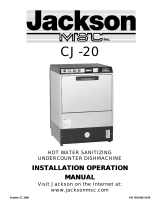
CONSERVER 24LT/CONSERVER 24LTP DIMENSIONS
11
Legend:
A.- Drain Connection flexible hose.
6’-0” free length, 1” ID x 1 3/8 OD
B.- Electrical Connection.
C.- Water Inlet-1/2” Female Pipe Thread,
2 1/2” AFF
D.-Detergent Feeder Connection
Note: All dimensions from floor can be increased 1”
with adjustable feet supplied.
Dimensions:
Height (minimum) 33 1/4”
Height (maximum) 34 1/4”
Width 24 1/4”
Depth 22 5/8”
Wall Clearance (minimum) 2 1/2”
Inside Clearance Height 14 1/2”
Inside Clearance Width 20 1/4”
Inside Clearance Depth 21 1/4”
Door Open Depth 39 1/2”

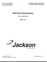
12
Conserver 24LT
ELECTRICAL DIAGRAM
115 volt - 60 hertz - single phase

Conserver 24LTP
ELECTRICAL DIAGRAM
115 volt - 60 hertz - single phase
13

ALABAMA
Jones-McLeod Appliance
1616 7th Avenue North
Birmingham, AL 35203
(205) 251-0159
(800) 821-1150
(205) 322-1440 fax
Jones-McLeod Appliance
854 Lakeside Drive
Mobile, AL 36693
(334) 666-7278
(800) 237-9859
(334) 661-0223 fax
ALASKA
Restaurant Appliance Service
7219 Roosevelt Way NE
Seattle, WA 98115
(206) 524-8200
(800) 433-9390
(206) 525-2890 fax
ARIZONA
GCS Service, Inc. #78
5052 South 40th Street
Phoenix, AZ 85040
(602) 474-4510
(800) 510-3497
(602) 470- 4511 fax
Authorized Commercial
Food Equipment Service
4832 South 35th St.
Phoenix, AZ 85040
(602) 234-2443
(800) 824-8875
(602) 232-5862 fax
ARKANSAS
Bromely Parts & Service
10th & Ringo
P.O. Box 1688
Little Rock, AR 72202
(501) 374-0281
(800) 482-9269
(501) 374-8352 fax
Commercial Parts & Service
3717 Cherry Road
Memphis, TN 38118
(901) 366-4587
(800) 262-9155
(901) 366-4588 fax
CALIFORNIA
P & D Appliance
4220-C Roseville Road
North Highlands, CA 95660
(916) 974-2772
(800) 824-7219
(916) 974-2774
CALIFORNIA (cont)
P & D Appliance
100 South Linden Avenue
S. San Francisco, CA 94080
(650) 635-1900
(800) 424-1414
(650) 635-1919 fax
Barkers Food
Machinery Equipment
5367 Second Street
Irwindale, CA 91706
(626) 960-9390
(800) 258-6999
(626) 337-4541 fax
GCS Service, Inc. #24
1100 East Pico Blvd
Los Angeles, CA 90021
(213) 683-2090
(800) 327-1433
(213) 683-2099 fax
GCS Service, Inc. #24
650 S. Grand Avenue
Suite 111
Santa Ana, CA 92705
(714) 542-1798
(800) 540-0719
(714) 542-4787 fax
GCS Service, Inc. #52
360 Littlefield
S. San Francisco, CA 94080
(650) 635-0720
(800) 969-4427
(650) 871-4019 fax
GCS Service, Inc. # 84
9030 Kenamar Drive
Suite 313
San Diego, CA 92121
(858) 549-8411
(800) 422-7278
(858) 549-2323 fax
COLORADO
GCS Service, Inc. #60
4251 S. Natches Ct.
Unit C
Sheridan, Co 80110
(303) 371-9054
(800) 972-5314
Metro Appliance Service
1640 South Broadway
Denver, CO 80210
(303) 778-1126
(800) 525-3532
(303) 778-0268 fax
CONNECTICUT
GCS Service, Inc. #06
302 Murphy Road
Hartford, CT 06114
(860) 549-5575
(800) 423-1562
(860) 527-6355 fax
DELAWARE
Food Service Equipment
2101 Parkway South
Broomall, PA 19008
(610) 356-6900
(610) 356-2038 fax
GCS Service, Inc. #44
817 N. Third Street
P.O. Box 3564
Philadelphia, PA 19123
(215) 925-6217
(800) 441-9115
(215) 925-6208 fax
Elmer Schultz Service
36 Belmont Ave.
Wilmington, DE 19804
(302) 655-8900
(800) 225-0599
(302) 656-3673 fax
EMR Service Division
106 Willamsport Circle
Salisbury, MD 21804
(410) 543-8197
(410) 543-4038 fax
FLORIDA
GCS Service, Inc. #15
3373 N. W. 168th Street
Miami, FL 33056
(305) 621-6666
(800) 766-8966
(305) 621-6656 fax
Commercial Appliance Service
8416 Laurel Fair Circle
Building 6, Suite 114
Tampa, FL 33610
(813) 663-0313
(800) 282-4718
(813) 663-0212 fax
GCS Service, Inc. #14
3902 Corporex Park Drive
Suite 350
Tampa, FL 33619
(813) 626-6044
(800) 282-3008
(813) 621-1174
JACKSON MAINTENANCE & REPAIR CENTERS (USA)
14

FLORIDA (cont)
GCS Service, Inc. # 13
4305 Vineland Road
Suite G-12
Orlando, FL 32811
(407) 841-2551
(800) 338-7322
(407) 423-8425 fax
Jones-McLeod Appliance
854 Lakeside Drive
Mobile, AL 36693
(334) 666-7278
(800) 237-9859
(334) 661-0223 fax
GEORGIA
GCS Service, Inc. #16
3127Presidential Dr.
Atlanta, GA 30340
(770) 452-7322
(300) 334-3599
(770) 452-7473 fax
Southeastern
Restaurant Service
2200 Norcross Pkwy,
Suite 210
Norcross, GA 30071
(770) 446-6177
(800) 235-6516
(770) 446-3157 fax
Whaley Foodservice Repairs
109-A Owens Industrial Drive
Savannah, GA 31405
(912) 447-0827
(888) 765-0036
(912) 447-0826 fax
HAWAII
Food Equipment Parts &
Service Co.
300 Puuhale Road
Honolulu, HI 96819
(808) 847-4871
(808) 842-1560 fax
IDAHO
Ron’s Service
703 E. 44th Street, Suite 10
Garden City, ID 83714
(208) 375-4073
(208) 375-4402 fax
Restaurant Appliance Service
7219 Roosevelt Way Ne
Seattle, WA 98115
(206) 524-8200
(800) 433-9390
(206) 525-2890 fax
ILLINOIS
GCS Service Inc. #12
696 Larch Avenue
Elmhurst, IL 60126
(630) 941-7800
(800) 942-9689
(630) 941-6048 fax
Cone’s Repair Service
2408 40th Avenue
Moline, IL 61265
(309) 797-5323
(800) 716-7070
(309) 797-3631 fax
Eichenauer Services, Inc.
130 S. Oakland Street
Decatur, IL 62522
(217) 429-4229
(800) 252-5892
(217) 429-0226 fax
GCS Service, Inc. #80
9722 Reavis Park Drive
St. Louis, MO 63123
(314) 638-7444
(800) 284-4427
(314) 638-0135 fax
INDIANA
Commercial Parts and Service
5310 E. 25th Street
Indianapolis, IN 46218
(317) 545-9655
(800) 727-8710
(317) 549-6286 fax
IOWA
Goodwin-Tucker Group
3509 Delaware Avenue
Des Moines, IA 50313
(515) 262-9308
(800) 372-6066
(515) 262-2936 fax
Cone’s Repair Service
1056 27th Ave. SW
Cedar Rapids, IA 52404
(319) 365-3325
(800) 747-3326
(319) 365-0885 fax
KANSAS
GCS Service Inc. #82
6107 Connecticut
Kansas City, MO 64120
(816) 920-5999
(800) 229-6477
(816) 920-7387 fax
KENTUCKY
Certified Service Center
Ramco Business Park
4283 Produce Road
Louisville, Ky 40218
(502) 964-7007
(800) 637-6350
(502) 964-7202 fax
Commercial Parts & Service
4204 South Brook Street
Louisville, KY 40214
(502) 367-1788
(800) 752-6160
(502) 367-0400 fax
Certified Service Center
1051 Goodwin Drive
Lexington, KY 40505
(606) 254-8854
(800) 432-9269
(606) 231-7781 fax
Commercial Parts & Service
1002 Nandino Blvd.
Lexington, KY 40511
(606) 255-0746
(800) 432-9260
(606) 255-0748 fax
LOUISIANA
Bana Parts, Inc.
1501 Kueble Street
Harahan, LA 70123
(504) 734-0076
(800) 325-7543
(504) 734-8456 fax
Bana Parts, Inc.
4028 Greenwood Road
Shreveport, LA 71109
(318) 631-6550
(800) 832-6550
(318) 636-5675 fax
MAINE
GCS Service, Inc. #09
180 Second Street
Chelsea, MA 02150
(617) 889-9393
(800) 225-1155
(617) 889-1222 fax
Massachusetts Restaurant
Supply
34 South Street
Somerville, MA 02143
(617) 868-1930
(800) 338-6737
(617) 868-5331 fax
JACKSON MAINTENANCE & REPAIR CENTERS (USA)
15

MARYLAND
GCS Service, Inc. #07
2660 Pittman Drive
Silver Spring, MD 20910
(301) 585-7550 (DC)
(410) 792-0388 (Balt)
(800) 638-7278
(301) 495-4410 fax
EMR Service Division
700 East 25th Street
Baltimore, MD 21218
(410) 467-8080
(800) 879-4994
(410) 467-4191 fax
EMR Service Division
106 Willamsport Circle
Salisbury, MD 21804
(410) 543-8197
(888) 687-8080
(410) 548-4038 fax
EMR Service Division
2626 Pittman Drive
Silver Spring, MD 20910
(301) 588-8080
(800) 348-2365
(301) 588-6985 fax
MASSACHUSETTS
GCS Service, Inc. #09
180 Second Street
Chelsea, MA 02150
(617) 889-9393
(800) 225-1155
(617) 889-1222 fax
Massachusetts Restaurant
Supply
34 South Street
Somerville, MA 02143
(617) 868-1930
(800) 338-6737
(617) 868-5331 fax
Ace Service Co.
95 Hampton Avenue
Needham, MA 02494
(781) 449-4220
(800) 225-4510 MA & NH
(781) 444-4789 fax
GCS Service, Inc. #06
302 Murphy Road
Hartford, CT 06114
(860) 549-5575
(800) 723-1562
(860) 527-6355 fax
MICHIGAN
GCS Service, Inc. #20
31829 West Eight Mile Road
Livonia, MI 48152
(248) 426-9500
(800) 772-2936
(248) 426-7555 fax
GCS Service, Inc. #21
3516 Roger B Chaffe SE
Grand Rapids, MI 49548
(248) 426-9500
(800) 772-2936
(248) 426-7555 fax
Jackson Service
3980 Benstein Road
Commerce Township, MI 48382
(248) 363-4159
(800) 332-4053
(248) 363-5448 fax
MINNESOTA
GCS/Metro Service, Inc.
2857 Louisiana Avenue N.
Minneapolis, MN 55427
(612) 546-4221
(800) 345-4221
(612) 546-4286 fax
MISSISSIPPI
Commercial Parts & Service
5755 Gallant Drive
Jackson, MS 39206
(601) 956-7800
(800) 274-5954
(601) 956-1200 fax
Commercial Parts & Service
3717 Cherry Road
Memphis, TN 38118
(901) 366-4587
(800) 262-9155
(901) 366-4588 fax
MISSOURI
GCS Service, Inc. #82
6107 Connecticut
Kansas City, MO 64120
(816) 920-5999
(800) 229-6477
(816)920-7387 fax
GCS Service, Inc. # 80
9722 Reavis Park Drive
St. Louis, MO 63123
(314) 638-7444
(800) 284-4427
(314) 638-0135 fax
MISSOURI (cont)
Kammerlin Parts & Service
2728 Locust Street
St. Louis, MO 63103
(314) 535-2222
(314) 535-6205 fax
MONTANA
Restaurant Appliance Service
7219 Roosevelt Way NE
Seattle, WA 98115
(206) 524-8200
(800) 433-9390
(206) 525-2890 fax
NEBRASKA
Goodwin-Tucker Group
815 N. 19th Street
Omaha, NE 68102
(402) 345-7400
(800) 228-0342
(402) 346-6145 fax
NEVADA
GCS Service, Inc. #77
3585 East Patrick Lane
Suite 1000
Las Vegas, NV 89102
(702) 450-3495
(800) 500-9060
(702) 450-3491 fax
Burney’s Commercial Service
4480 Aldevaran Avenue
Las Vegas, NV 89103
(702) 736-0006
(702) 798-7531 fax
NEW HAMPSHIRE
GCS Service, Inc. #09
180 Second Street
Chelsea, MA 02150
(617) 889-9393
(800) 225-1155
(617) 889-1222 fax
Massachusetts Restaurant
Supply
34 South Street
Somerville, MA 02143
(617) 868-1930
(800) 338-6737
(617) 868-5331 fax
Ace Service Co.
95 Hampton Avenue
Needham, MA 02494
(781) 449-4220
(800) 225-4510 MA & NH
(781) 444-4789 fax
JACKSON MAINTENANCE & REPAIR CENTERS (USA)
16

NEW JERSEY
Jackson Faspray Service
155 Sargeant Avenue
Clifton, NJ 07013
(973) 471-8000
(800) 356-6740
(973) 471-1289 fax
GCS Service, Inc. #44
817 N. Third Street
Philadelphia, PA 19123
(215) 925-6217
(800) 441-9115
(215) 925-6208 fax
GCS Service, Inc. #02
1 Madison ST., Bldg. F
E. Rutherford, NJ 07073
(973) 614-0003
(800) 399-8294
(973) 614-0320 fax
Food Service Equipment
2101 Parkway South
Broomall, PA 19123
(610) 356-6900
(610) 356-2038 fax
NEW MEXICO
Stove Parts Supply Co.
2120 Solana Street
Ft. Worth, TX 76117
(817) 831-0381
(800) 433-1804
(817) 834-7754 fax
NEW YORK
GCS Service, Inc. #01
932 Grand Street
Brooklyn, NY 11211
(718) 486-5220
(800) 969-4271
(718) 486-6772 fax
Duffy’s Equipment Service
3138 Oneida Street
Sauquiot, NY 13456
(315) 737-9401
(800) 443-8339
(315) 737-7132 fax
B.E.S.T., Inc.
3003 Genesee Street
Buffalo, NY 14225
(716) 893-6464
(800) 338-5011
(716) 893-6466 fax
NEW YORK (cont)
Appliance Installation &
Service Corp.
1336 Main Street
Buffalo, NY 14209
(716) 884-7425
(800) 722-1252
(716) 884-0410 fax
Northern Parts & Service
21 Northern Avenue
Plattsburgh, NY 12903
(518) 563-3200
(800) 634-5005
(800) 782-5424 fax
Jackson Faspray Service
155 Sargeant Avenue
Clifton, NJ 07013
(973) 471-8000
(800) 356-6740
(973) 471-1289 fax
NORTH CAROLINA
Whaley Foodservice Repairs
8334-K Arrowridge Blvd.
Charlotte, NC 28273
(704) 529-6242
(704) 529-1558 fax
Whaley Foodservice Repairs
203-D Creek Ridge Road
Greensboro, NC 27406
(336) 333-2333
(336) 333-2533 fax
Whaley Foodservice Repairs
335-105 Sherwee Drive
Raleigh, NC 27603
(919) 779-2266
(919) 779-2224 fax
Whaley Foodservice Repairs
6418-101 Amsterdam Way
Wilmington, NC 28405
(910) 791-0000
(910) 791-6662 fax
NORTH DAKOTA
GCS/Metro Service Inc.
2857 Louisiana Avenue N.
Minneapolis,MN 55427
(612) 546-4221
(800) 345-4221
(612) 546-4286 fax
OHIO
Certified Service Center
890 Redna Terrace
Cincinnati, OH 45215
(513) 772- 6600
(800) 543-2060
(513) 612-6600 fax
OHIO (cont)
Commercial Parts &
Service of Columbus
1150 West Mound Street
Columbus, OH 43223
(614) 221-0057
(800) 837-8327
(614) 221-3622 fax
GCS Service, Inc.
2830 Johnstown Rd.
Columbus, OH 43219
(614) 476-3225
(800) 282-5406
(614) 476-1196 fax
Electrical Appliance
Repair Service
5805 Valley Belt Road
Cleveland, OH 44131
(216) 459-8700
(800) 621-8259
(216) 459-8707 fax
OKLAHOMA
Krueger Inc.
100 NE 24th Street
Oklahoma City, OK 73105
(405) 528-8883
(800) 522-8069
(405) 528-5405 fax
Hagar Restaurant Equipment
1229 W. Main Street
Oklahoma City, OK 73106
(405) 235-2184
(800) 445-1791
(405) 236-5592 fax
OREGON
Ron’s Service
16364 SW 72nd Ave.
Portland, OR 97224
(503) 624-0890
(800) 851-4118
(503) 684-6107 fax
PENNSYLVANIA
GCS Service, Inc. #44
817 N. Third Street
P.O. Box 3564
Philadelphia, PA 19123
(215) 925-6217
(800) 441-9115
(215) 925-6208 fax
Elmer Schultz Service
540 North 3rd Street
Philadelphia, PA 19123
(215) 627-5400
(215) 627-5408 fax
JACKSON MAINTENANCE & REPAIR CENTERS (USA)
17
/