MODEL 10LT AUTOMATIC
DISHWASHER
LOW TEMPERATURE CHEMICAL SANITIZING
ROUND DISHMACHINE
INSTALLATION, OPERATION AND
SERVICEMANUAL
INCLUDES:
WORLD HEADQUARTERS & MANUFACTURING OPERATIONS
Highway 25E, P.O. Box 1060
Barbourville, KY 40906
888/800-JMSC. Fax 606/523-9196
March 12,1999 (Reprinted without change) P/N 7610-100-05-00
-
Warranty Policy
-Operating Instructions
-Description of Components
-Troubleshooting Guide
-
Installation Requirements
-Basic Functions of Dishwasher
-Maintenance and Care
-Wiring Diagrams

INDEX
SPECIFICATIONS 3
GENERAL INSTRUCTIONS (installation/Dimensions) 4
GENERAL INSTRUCTIONS (Operation 6
SEQUENCEOFMACHINEOPERATIONS 7
GENERAL INSTRUCTI0NS (Preventive Maintenance) 7
REMOVALOF WASH HEADASSEMBUES 8
TIME FOR MODEL10LT DISHWASHERS 10
DEFECTIVETIMER MOTOR 11
FUNCTION of CIRCUIT BREAKER, SWITCHES,
and INDICATOR LIGHT 12
REPLACEMENTS SWITCHES in CONTROL PANEL 13
DISPENSING SYSTEM for SANITIZING AGENT 14
PERISTALTIC PUMP SANITIZING DISPENSING
SYSTEM (Operation) 15
REPLACING SEAL and CERAMIC on WASH
And RINSE PUMP 16
GENERAL INSTRUCTIONS for DRAIN VALVE 18
DRAIN VALVE ASSEMBLY 19
SERVICE INSTRUCTIONS 20
TROUBLE SHOOTING GUIDE 21
PICTORIALS
FRONT VIEW OF MACHINE 25
BACKVIEWOFMACHINE 26
RIGHTSIDEV1EWOFMACHINE 27
BOTTOM VIEWOF MACHINE 28
BASEVIEW 29
SUPPORT PIPE ASSEMBLY and HOOD ASSEMBLY 30
WASH and RINSE THERMOMETER, VACUUM
BREAKER and INCOMING PLUMBING 31
SANITIZING AGENTINJECTOR 32
CONTROLBOX and CONTROL PANEL COMPONENTS 33
WIRING DIAGRAM 34
PARTS LIST 35
PARTS DISTRIBUTORS Inside Back Cover

SPECIFICATIONS
OPERATING CAPACITY 100% 10LT
Racks per hour 43
Dishes per hour 910
Glasses per hour 910
OPERATING CYCLE
Wash time - seconds 28
Rinse time - seconds 15
Total cycle - seconds 75
WASH TANK CAPACITY
Gallons 2.3
RINSE TANK CAPACITY
Gallons N/A
WASH PUMP CAPACITY
Gallons per minute 70
WATER REQUIREMENTS 100%
Inlet Temperature ºF 120-140
Gallons per hour 100
Flow Pressure, PSI 20
Flow, gallons per minute 10
Inlet size - IPS 3/4"
Drain size - IPS 1-1/2"
WASH PUMP MOTOR
Horsepower 1/2
RINSE PUMP MOTOR
Horsepower 1/2
WASH HEATER, KW N/A
RINSE HEATER, KW N/A
DIMENSIONS
Hood outside diameter 19"
Hood height above table 191/4"
Base outside diameter 21"
Depth below table level
(without legs) 16"
Standard table height,
legs furnished 34"
Maximum height for dishes 14"
Rack size 171/2" dia.
10L Series Tested at NSF Available
Using 5.25% Chlorine 50 PPM
Sodium Hypochlorite for Sanitizing
ELECTRICAL RATING. MODEL 10L
Volts Phase Approximate Total
Load Amps
115
1
12
3

GENERAL INSTRUCTIONS
(INSTALLATIONS/DIMENSIONS)
Note: Read the following instructions carefully. Proper installation of your Jackson
Dishwasher will assure proper machine operation.
1. With machine base set in place, lift the table (with proper flanged cutout) over and above machine so
that vertical flange on table cutout fits down inside of machine tub and horizontal flange on machine tub
fits up tight against underside of the table.
2. Ease vacuum breaker piping supplied down through square cutout in the backsplash of table (directly
behind machine).
3. Connect vacuum breaker piping to machine. The top union connects to its matching half on the bottom
of the hood support block.
4. The bottom union of the piping connects to an adaptor pipe which, In turn, connects to
the solenoid valve. The arrows on the solenoid valve Indicate the direction of water
flow to the machine. Tighten both connections.
5. Adjust machine base until small hole (1-7/8" diameter) behind large flanged hole, lines up
with hole in support block of machine.
6. Insert internal vacuum breaker pipe (taped to hood support pipe) into support block with large end
down and pinned end up. It should set in snug, retaining ring will prevent it from being inserted too far.
7. Lift hood and hood support pipe up over table and machine to clear the internal vacuum breaker
pipe. Slide hood support pipe down over internal pipe and work support pipe down into support block
hole. Locating pin will insure proper line up.
8. Make sure there are two "0" rings on lower support pipe near end ring.
9. While holding support pipe, start tightening nut by hand to prevent cross threading. It should tighten
considerably by hand. Then continue tightening with a wrench. It may be necessary to work support pipe
back and forth to seat nut properly.
10. When nut is tight, it should force flat the stainless steel and rubber washers tight to table top.
11. Rotate hood to insure it is free; if not, check level of machine, tightness of table to machine flange,
centering of machine, level of table and hood support pipe. See instructions in manual for adjustments.
12. Connect drain to bottom of machine (1-1/2" IPS female fitting on bottom of machine) to conform with
local and/or national codes. Drain Is a gravity feed system from machine.
13. Connect incoming 3/4" water line with capacity to supply 10 gallons per minute, flow at 20 PSI at a
constant temperature of 120º-140ºF. This connection Is Just before the flow restrictor. Connect to
conform with local and/or national codes (standards).
14. Electrical connections should be made through hole in bottom of control box to terminal board inside
(to the right lower side of control box). This terminal board is accessible by removing the lower cover
plate on control box. The terminals are marked LI and N. There is a grounding lug inside the control box
on the bottom left. Be sure all connections made are tightened properly.
15. Install the proper circuit breaker, wire and conduit size to conform with local and/or national codes.
Refer to data plate for electrical loads.
16. Do not apply power until step #20.
17. Remove all shipping tape holding drain strainer, wash head, rack support, etc., and assemble.
18. The sanitizing agent dispensing pump is located on the front shroud of the machine. Fill the opaque
storage bottle that is provided with the machine to about 3 inches from the top with 5.25% Sodium
Hypochlorite (FDA approved). Place the full bottle in the holder on the front right side of the machine.
Insert the hose that leads to the left side of the pump into the storage bottle. The hose from the other
side of the pump is connected to a fitting in the back of the unit.
19. Insert drain and pump strainers and then close hood.
4

20. Turn on water supply to machine, check for any leaks In plumbing and connections. To
energize electrically, proceed as follows:
a. Turn on customer's circuit breaker controlling machine.
b. Check voltage at incoming terminal L1 and Neutral. It should match data plate
voltage. Voltage at L1 and N should be checked to ground individually to insure
that a high (or wild) leg is not connected. (Voltage exceeding 150V to ground would
indicate high leg.)
c. If voltage is in required range, turn on 15 amp circuit breaker on side of control box.
d. Turn on master switch only.
e. Lift fill switch and hold for approximately 20 seconds. This will not fill wash tank to
overflow level. Check for any leaks and tighten where necessary. If no leaks are
present, continue to fill by holding the rinse/fill switch.
f. Open hood and check water level, it should be up about 1 1/2" deep in round tub.
Check water line making sure valve fully opens and closes as the switch is turned
on and off.
g. Lift the primer switch on the control panel. Observe the face of the pump and
watch to see if the cam roller rotates. If it rotates, continue to hold the switch up
with the hood open until the sanitizing agent passes through the pump and drops
into the machine in the back. If the cam roller does not rotate, check page 15.
h. If water is at proper level, close hood and turn on start switch. Run through one or
two full cycles to make sure wash pump water runs, drain opens and fresh water
solenoid lets water in.
i. Dishwasher is now ready to proceed with washing of dishes in accordance with
operating instructions in this manual and instruction sticker on hood of dishwasher.
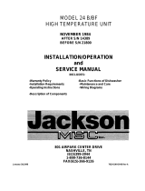
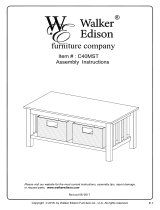
A. INLET 3/4" IPS
B. DRAIN 1-1/2" IPS
C. ELECTRICAL CONNECTION
D. CLEARANCE TO WALL
E. CLEARANCE FOR MAXIMUM
DISH HEIGHT OF 14" F. RATING PLATE
5

GENERAL INSTRUCTIONS
(OPERATION)
Note: Read the following instructions carefully. Proper operation of your Jackson
Dishwasher will assure clean and sanitized glasses and dishes at optimum
efficiency.
Dish Preparation:
1. Scrape dishes thoroughly.
2. Pre-wash dishes by soaking or spraying with pre-rinse hose.
3. Place dishes and cups in dish rack; cups upside down.
4. Place the glasses upside down in the open rack. With the Model 10, a four
compartment silverware rack is supplied. Place silver In compartment rack loosely, not allowing it to
mix with other silverware of the same nature. Place the compartment rack in the open rack and wash
with glasses or cups taking up excess area.
Operator's Instructions:
1. Make sure drain and pump intake strainer are clean and in place. For the first rack of a new meal
period (when the machine is empty of water) slide an empty rack into the machine.
2. Close door and turn on master switch.
3. Lift fill switch and hold for approximately 20 seconds.
4. Open hood and slide soiled dishes into machine.
5. Dispense proper amount of detergent in machine and close hood.
6. Start machine by flipping start switch either up or down. Note: The start switch Is three
positions: up = start, center = off, down = start. Indicator light will come on during automatic
cycle.
7. When center light goes out, cycle has ended. Open hood, slide out rack of clean dishes. Slide
in rack of soiled dishes, and repeat steps 6,7, and 8. (Add detergent, close hood and flip start
switch in opposite direction.)
8. At end of meal time, shut off by placing start switch in center position. Drain machine by lifting drain
switch and holding for approximately 30 seconds. Remove drain strainers after water has drained
and clean. Clean wash head and replace clean strainers.
Detergent Recommendations and Rinse Additives:
We suggest that you contact your local Detergent Specialist for the correct detergent and rinse additives
for your area. To help you until one can be reached, we suggest that you use a non-foaming dishwasher
detergent, approximately one tablespoon in wash tank when machine is filled, and one tablespoon each
cycle or load thereafter. This may have to be increased or decreased to obtain satisfactory results.
When manually dispensing powdered detergent in wash tub always distribute over a sufficient area to
prevent build up. Some detergent, when dispensed in a small or concentrated area, may cause
deterioration of the stainless tub or sump.
6

SEQUENCE of MACHINE
OPERATIONS
1. Start switch depressed.
2. Timer motor activated.
3. Wash/rinse cam switch activates motor for wash.
4. Wash ends, drain cam switch activates drain valve.
5. Drain ends, fill solenoid and peristaltic pump activated (dropping sanitizing agent in
rinse water) by fill and pump cam.
6. Wash/rinse cam switch activates motor for rinse as fill ends.
7. Timer motor deactivated and cycle ends.
GENERAL INSTRUCTIONS
(PREVENTIVE MAINTENANCE)
THE FOLLOWING IS TO BE PERFORMED AS NEEDED.
Note: Read the following instructions carefully. Proper maintenance of your
Jackson Dishwasher will assure optimum service with a minimum of down time.
1. Remove all lime and corrosion deposits. (Always protect hands with waterproof
gloves to reduce chance of Irritation.)
a. Fill the machine with wash water as would ordinarily be done for washing.
b. Remove hose from sanitizing agent bottle.
c. Open door and place one cup or less of deliming compound into the water. (Be sure
to follow the directions on the compound label if they vary from these being given.)
The compound is available from your detergent supplier.
d. Turn on the start switch and allow to go through one cycle.
e. Open door and examine the interior. All lime should be removed and parts should
be shiny. If not, add more deliming compound and recycle.
f. After the interior is clean, empty the wash water by holding drain switch for
approximately 30 seconds.
g. Refill machine and allow to run through a cycle, repeating this operation twice.
h. Refill as it is ready for regular operation.
2. Clean strainers.
a. Clean around sump opening, flat strainers and pump Intake strainer holes. b. Clean
around pump intake (toothbrush makes excellent tool for cleaning).
3. Clean Y-strainer on incoming water line. (Water to machine must be turned 'off' for this
operation.) a. Remove plug and clean strainer.
4. Clean wash head assembly.
a. If spray jets are plugged, straighten a paper clip and use as a tool to dislodge and
flush with clean water.
b. If lodged items still remain in wash tubes, remove wash assembly.
c. Clean assembly at sink by flushing water through spray jets.
d. Reinstall wash assembly. (See page with instructions.)
5. Clean any deposits which may have built up on exterior moving parts.
7

REMOVAL of WASH HEAD
ASSEMBLIES
General Instructions:
1. With the hood closed, lift the drain switch and hold it for 30 seconds.
2. Open the hood.
3. Lift out the rack support rod assembly.
4. Clean the flat drain and pump intake pump strainers. Then replace.
5. Locate the Allen head set screw in the wash head cap, insert an Allen wrench and loosen the screw
by turning counterclockwise.
6. Turn the wash head cap counterclockwise until cap is removed and put the cap in a safe place.
7. Remove the 1/4" stainless ball bearings carefully and put in a receptacle in a safe place. If any
should drop in machine, you will be able to locate and retrieve if you replaced the flat strainer as
suggested in #3 above.
8. Lift and remove the small manifold with the short tubes. Put it in a safe place.
9. Remove the 1/4" ball bearing in a similar method to step #7-
10. Lift and remove the large manifold with the long length tubes similar to step #8.
11. The lower fixed race may be left in place.
12. Clean the ball bearings by soaking in a deliming solution.
13. The ball bearing race ways may be cleaned by either brushing with a deliming solution (toothbrush
makes an excellent tool) or gently clean by rubbing with fine sandpaper or emery cloth.
14. Rinse the ball bearings and manifolds thoroughly.
15. To reassemble, first, fill the lower race to capacity with 1/4" ball bearings, then remove one. This will
give proper movement needed during rotation of assembly.
16. Replace lower manifold and fill race fully with 1/4" ball bearings. Repeat, removing one only.
17. Replace upper manifolds and repeat necessary parts of step #15.
18. Replace wash cap by screwing on center shaft clockwise, finger tight.
19. Back off wash cap about % turn and tighten Allen set screw.
20. Rotate manifolds in opposite directions, see if they rotate freely. A rule of thumb is to select the
longest tube in the bottom manifold and make sure it moves up and down at least 1/8" and no more
than 1/4".
21. Close the hood doors and refill the dishwasher.
22. Run through several cycles and recheck wash arms for easy movement Adjust if necessary.
23. Replace rack support rod assembly.
8

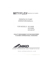
WASH/RINSE HEAD ASSEMBLY P/N 1860
ITEM
P/N
DESCRIPTION
1. 1865 WASH CAP
2. 1870 WASH CAP SET SCREW
3. 1940 BALL BEARINGS (3 PLACES)
4.
1875
CENTER SHAFT
5. 1925 SMALL MANIFOLD
6. 1945 SPRAY TUBE (12 PLACES)
7.
1930
LARGE MANIFOLD
8.
1935
FIXED RACE
9.
447
HOLDING NUT
10.
1885
HOLDING BOLT
11.
WASH HEAD BASE
9

TIMER FOR MODEL 10LT
DISHWASHERS
General Description:
The timer is a self-contained (frame mounted) timer of the repeating cycle type. It is mounted in the control panel of
the Jackson Dishwashing Machine to control the automatic functions of this machine. It consists of a clock motor
which operates on 60 cycle, 110VAC. In addition to the clock motor, the timer also contains a driven cam
arrangement which operates five micro switches.
Principle of Operation:
The timer controls various operations of the automatic washer as per wiring diagram for each machine;
however, the timing cycle and the micro switches are the same for each model. The time for one complete
revolution of the cam shaft Is approximately 150 seconds allowing two wash and two rinse operations for
each complete revolution of the cam shaft. The micro switch nearest the timer motor is the hold circuit and
uses both the NO and NC contacts. The micro switch second from the timer motor controls the wash/rinse
and uses the NC contact. The micro switch third from the timer motor controls the rinse/fill and uses Just
the NC contact. The micro switch fourth from the timer motor controls the drain and uses just the NC
contact. The last micro switch, fifth from the timer motor, controls the peristaltic pump and uses just the
NC contact.
Service Instructions:
Caution: Always remove the power to the machine before working on the control panel or while servicing
the components in the door panel. All electrical checks should be made by qualified personnel.
Remove power to machine while attempting removal of control panel from box.
Timer operation can be observed after removing the control panel from the control box by loosening the
four screws holding it. Hang the control panel using the two right hand screws with the back side of the
panel outward.
If it is determined that the timer is defective, it is recommended that a new time be Installed. However, limited
field maintenance can be accomplished as explained below:
A frozen contact on a micro switch will be indicated by one function being executed all the time or the absence
of a click when the switch arm is actuated.
To Replace Micro Switch:
1. Remove all wires from the timer and properly tag them to assure proper replacement
2. Remove all screws which hold the timer to the control panel.
3. One screw holds the micro switches, cams and actuating arms in the frame. This screw is seen on the side
opposite the motor. Remove this screw. Note: Be sure to note which cam goes with which micro switch.
Cam nearest timer motor has 1/2 raised and 1/2 depressed.
4. The unit can now be taken apart and the defective micro switch replaced.
5. Reassemble. Note: The flanges on the cams are such that they only mesh in one direction.
The timer's cam drive system is equipped with a clutch to enable one to view the operations of the cams and micro
switches. Remove power to machine before touching timer. Rotate cams by turning with fingers; cams will turn in
one direction, only. Do not force them. As cams actuate switches, listen for the 'click' of the switch or test the
switches with an ohmmeter.
10

DEFECTIVE TIMER MOTOR
Caution: Always remove the power to the machine before working on the control panel or while
servicing the components In the door panel. All electrical checks should be made by
qualified personnel.
A defective motor is indicated by the fact that the cams do not rotate or the machine does not
perform the automatic operations or performs a specific part of the cycle continuously, but works
okay on manual. Remember, the timer motor is controlled by the start switch and the hold micro
switch; check this complete circuit before changing motor.
To Replace Motor
1. Remove motor leads from shorting bar and neutral.
2. Remove the two screws which hold the motor.
3. Replace with a new motor.
Note: It may be necessary to remove complete timer to replace motor; if so, follow steps 1 and 2,
previous page.
11
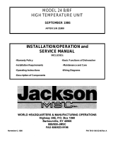
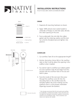
TYPICAL TIMER SWITCH
P/N1775
A - TO UPPER TERMINAL START SWITCH
B - TO LOWER TERMINAL START SWITCH
C - TO TERMINAL NUMBER 9 ON TB-2
D - TO TERMINAL NUMBER 10 ON F-SW
E - TO TERMINAL NUMBER 2 ON M-SW
F - SHORTING BAR CONNECTED TO ALL
THE THREE TIMER SWITCHES,
TO TERMINALS (ON REAR),
NUMBER 6 ON DIAGRAM
G -TO TERMINAL NUMBER 4 ON D-SW
H - TO TERMINAL NUMBER 5 ON PR-SW

FUNCTION of CIRCUIT BREAKER,
SWITCHES and INDICATOR LIGHT
Circuit breaker The circuit breaker is rated 15 amps and controls power to control circuit,
I.E. timer, solenoid valve, and motors. Circuit breaker does not cutoff power in control box at incoming
terminal board. Power is still applied only to the incoming terminal board when the circuit breaker is in 'off
position.
Operator Controls: The operator of this machine has five control switches which he can operate.
These switches are located across the top of the control panel.
1. The Master Switch activates operating controls.
2. The Start Switch initiates automatic operation of the machine by energizing timer. Switch Is
three positions: full up = start, middle = off, down = start.
3. The Drain Switch allows the User to manually drain the wash tank at the end of the meal period
and/or when cleaning is required. It is spring loaded and must be held approximately 30 seconds.
4. The initial Fill Switch allows the User to manually fill the machine before running it the first
time of each day. It is spring loaded and must be held approximately 20 seconds to fill machine.
5. The Primer Switch is used to fill the peristaltic pump and pump line with sanitizing solution
when a new bottle is utilized or the pump loses it's prime.
Indicator Light The signal light comes on when start switch is turned on and remains on until
cycle is over; then it turns off automatically to signal end of cycle.
12

REPLACEMENT of SWITCHES
in CONTROL PANEL
There are five switches installed in the control box cover panel. These are the master, start, drain,
fill and primer switches.
Before working on machine, trip breaker to off position. It is important that power be turned off at
customer's circuit breaker to prevent the possibility of electrical shock.
Remove control panel from control box by removing the four screws holding it in place. Hang the
control panel using the two right hand upper and lower screw receptacles on the control box with
backside of panel facing outward. The switches are mounted in individual round holes with a
keyway. By using a pair of pliers or open end wrench, it is possible to loosen the inside nut
enough to allow the outside nut holding the switch to be removed by fingers. Push switch out of
hole.
If a switch is found to be defective, replacement can be achieved by placing the new switch next
to the old one. To make sure the new switch is not upside down, line up with the keyways.
Transfer wires one at a time to the new switch. If this is not practical, pull wires off one at a time
and tag them for proper replacement.
Put switches back into panel; make sure switch protrudes through panel properly, tighten both
nuts, and replace control panel on control box. Power can now be applied to dishwasher and run
through cycles checking all operations.
1. CONNECTION TERMINALS
2. INSIDE NUT
3. PANEL PLATE
4. OUTSIDE NUT
5. BAT OR TOGGLE HANDLE
13

DISPENSING SYSTEM for
SANITIZING AGENT
Instructions: Filling the Storage Bottle and Dispenser Operation.
1. Check the level of the liquid in the opaque storage bottle setting in the holder on the
machine. You should be able to see liquid about 1" up from the bottom.
2. To refill, place a funnel in the top of the bottle and slowly transfer 5.25% of Sodium
Hypochlorite (FDA approved). Into the storage bottle. It may be necessary to remove the
bottle from the holder; if so, remove the hose from the mouth of the bottle first. Lift and place
the bottle onto a working surface and fill within 3" of the top. Wipe off any spillage.
Caution: Do not spill liquid on clothes or skin and avoid getting in eyes, as it is an irritant Rinse
immediately. Harmful if swallowed; call a physician immediately.
3. Replace the storage bottle in the holder with the hose in the mouth of the bottle.
14

PERISTALTIC PUMP SANITIZING
DISPENSING SYSTEM
(OPERATION)
The peristaltic pump is mounted onto the front shroud of the machine. The pump receives its electrical
signals from two sources.
The first source is the rinse/fill switch which is used to prime the pump when it is first put into operation
and then every time the unit is filled with fresh water to start a new meal period.
The second source is the timer which activates the pump during the wash cycle of the unit and allows it
to drop 15 milliliters of sanitizing solution into the holding tank.
Checkout of Sanitizing Agent Injector
The pump can be deemed operational if the following items are observed:
1. If the cam roller assembly rotates during each cycle.
2. If the solution is observed passing through the tube.
Note: Both of these operations must be observed to determine if the sanitizing agent is
being dispensed.
If it is determined that the unit is not operating correctly, the following procedures will aid in correcting the
problem:
1. Make certain that the tube is in the bottle of solution.
2. Make certain that there are no cracks in the tubing and particularly in the pump hose.
3. Check all wire connections on the pump, the timer cam, and the rinse/fill switch.
4. Check to see that there is no debris in the tubes.
5. Make sure that the tubing is inserted into the pump hose so that air is not drawn into the system.
15

REPLACING SEAL and
CERAMIC on WASH AND RINSE
PUMP
(SEE ILLUSTRATION NEXT PAGE)
Function:
The pump is part of the total motor-pump system and utilizes one seal and ceramic to
prevent the pump from leaking around the impeller and shaft. One gasket is used to
prevent leakage in between the pump mounting plate and the machine pump plate.
Replacement of Seal and/or Ceramic:
1. Drain machine by lifting drain switch for 30 seconds.
2. Remove power source to machine by turning circuit breaker to Its off position on
side of control box.
3. Support motor, remove the four nuts holding the pump/motor to the machine's
pump plate.
4. Carefully pull motor outward, move from side to side as required to remove from
machine.
5. Set motor and pump on a sturdy stand close to machine or remove wires and
conduit to allow motor/pump to be moved to a better work situation.
6. Remove dust cap over end of motor shaft (opposite impeller end). This can be
done by wedging with a screwdriver.
7. To remove impeller, hold shaft by inserting screwdriver in slotted end of shaft and
unscrew impeller in counterclockwise direction.
8. The ceramic is embedded in the Impeller and normally does not need replacement,
but It should be checked for cracks or a worn out surface. If ceramic does need
replacement, proceed as follows:
a. With a thin flat tool, work the ceramic and rubber cup out of groove in impeller.
b. Clean groove of all residue.
c. Apply small amount of adhesive In groove.
d. Press new ceramic gently Into groove with rubber cup leading the way. Note: The
ceramic has one side that is grooved. This side should be facing down Into the
rubber cup. The smooth surface should be facing up.
9. The seal is embedded in the pump mounting plate and usually will need replacement
when water leaks around motor shaft area. If replacement is required, proceed as
follows:
a. Remove four bolts holding pump mounting plate to motor. This must be done
with Allen wrench.
b. Slide mounting plate up off of shaft and motor.
c. Press seal out of housing carefully.
d. Clean hole where seal was installed.
e. Apply a small amount of non-hardening sealant to backside of seal. Insert new
seal with seat driver to prevent ruffling the edges of seal. Never use
screwdrivers or similar tools to alternately force edge of seal in place.
10. Reassemble pump and motor by reversing the above procedure.
11. Always replace pump gasket to insure good seal around pump cleaning.
16

PUMP & MOTOR ASSEMBLY
10L WASH & RINSE PUMP ASSEMBLY ASSEMBLY P/N 850
17
ITEM P/N DESCRIPTION
1. 860 PUMP MOTOR
2. 880 PUMP MOUNTING PLATE
3. 875 PUMP IMPELLER SEAL
4. 890 PUMP CERAMIC FACE W/ RETAINER CUP
5. 895 PUMP IMPELLER
6. 900 PUMP MOUNTING GASKET
7. 905 PUMP PLATE TO MOTOR
MOUNTING BOLTS
8. 910 MOUNTING PLATE LOCKWASHERS
9. 910
PUMP MOUNTING PLATE TO BASE
LOCKWASHERS
10. 915 PUMP MOUNTING PLATE TO BASE
NUTS
11. DUST CAP

GENERAL INSTRUCTIONS for
DRAIN VALVE
If Valve Fails To Open:
1. Pull manual drain chain.
2. Check to see that drain chain or lever is not jammed.
3. Check drain switch.
4. Check wiring and connections.
5. If gear motor is burned out; replace drain valve.
If Valve Fails To Close:
1. Look into top of machine drain for obstruction.
2. Check drain chain or lever to make sure they are not jammed.
3. Check gear motor shaft to ensure spring is not loose or broken.
4. Remove drain plumbing from lower no-hub connector and check valve for obstruction.
5. Replace drain valve if necessary.
18

DRAIN VALVE ASSEMBLY P/N 1433A
19
1.
VALVE SUPPORT BRACKET
2. 1-1/2" NO-HUB CONNECTORS
3. DRAIN BALL VALVE
4. 1-1/2" PVC MALE ADAPTOR
5. OVERFLOW TUBE
6. COVER BRACKET
7. GEAR MOTOR COVER
8. MANUAL DRAIN CHAIN

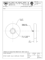
SERVICE INSTRUCTIONS
(INCOMING WATER SOLENOID VALVE)
SOLENOID
VALVE P/N
1434
To Take the Valve Apart
Disassembly — These valves may be taken
apart by unscrewing the bonnet and the
enclosing tube assembly from the valve body
assembly. See Fig. 3. After unscrewing,
carefully lift off the bonnet and enclosing
tube assembly. Don't drop the plunger. The
"0" ring seal and diaphragm cartridge can
now be lifted out.
Be careful not to damage the machined faces
while the valve is apart.
To Reassemble — Place the diaphragm
cartridge in the body with the pilot port
extension up. Hold the plunger with the
synthetic seat against the pilot port. Make
sure the "0" ring is in place, then lower the
bonnet and enclosing tube assembly over the
plunger. Screw bonnet assembly snugly
down on the body assembly.
DIAPHRAGM CARTRIDGE
Possible Problems:
Pilot Port extension #1 clogged. Hole
#2 clogged.
Remedy:
Pass heated straight pin through hole #2
or clean hole #1.
20
Page is loading ...
Page is loading ...
Page is loading ...
Page is loading ...
Page is loading ...
Page is loading ...
Page is loading ...
Page is loading ...
Page is loading ...
Page is loading ...
Page is loading ...
Page is loading ...
Page is loading ...
Page is loading ...
Page is loading ...
/