Page is loading ...

Revised 22 Dec 05
Revised 22 Dec 05
Notice: lift kits with 4” or more require a long arm kit. Part #LAT, #STL or
#LCG. 35” or larger tires will require upper adjustable ex arms.
Think safety rst when installing your new suspension system.
Use these instructions to install the TeraFlex 3, 4 or 5-inch lift kits.
Information regarding the installation of the TeraFlex “System” Compo-
nents are included after the lift installation instructions. The TeraFlex
3,4 and 5-inch lift kit you are about to install were designed specically
for the Jeep TJ.
Attention:
To eliminate drive line vibration on the 4 and 5-inch kits, a slip yoke elimi-
nator (short shaft kit - part number 231ESS) is mandatory.
Spring Spacer Warning:
The combination of spring spacers larger than the SSTX75 with any
TeraFlex spring will void any applicable warranties. Spring spacers may also
adversely affect vehicle handling, performance and safety.
Warning: For proper installation, the rear must be
installed rst to ensure proper placement of the
new front track bar mounting hole.
Disregard if you are installing the TeraFlex front
adjustable track bar, part # TBAF.
Installation Guide for the
TJ 3-inch, 4-inch, or 5-inch
lift kits (3T/4T/5T)
Tera Manufacturing, Inc.
5251 South Commerce Dr.
Murray, Utah 84107
Phone/801.288.2585
Fax/801.713.2313
www.teraex.biz
INSTALLATION GUIDE

Revised 22 Dec 05
Revised 22 Dec 05
Before starting installation, make sure that your kit
contains all the correct parts.
Your kit should contain:
2 rear springs (6.50” OD)
2 front springs (5.25” OD)
One installation kit including:
2 rear sway bar links
8 rubber bushings
4 plastic sleeves
5 at washers (1/2” SAE)
2 self-tapping bolts (3/8” x 2”)
2 front bumpstop spacers (3” OD x 2.25” tall)
1 rear track bar bracket
1 rear track bar spacer (1.5” x 1” OD x .5” ID)
7 bolts (1/2” x 3” nc)
7 lock washers (1/2”)
6 round spacers (1.25”OD x 1.25” tall)
6 beveled washers
2 bolts (5/16” x 1” nf)
2 lock nuts (5/16” nf)
2 at washers (5/16” SAE)
1 drop pitman arm (for power steering only)
1 bolt (10mm x 75mm)
1 lock nut (10mm)
Special items for the 3-inch kit:
2 bolts (10mm x 55mm)
2 rear bumpstop spacers (1.75”OD x 1.5” tall)
Special items for the 4 and 5-inch kit:
2 bolts (10mm x 75 mm 1.5p)
2 rear bump stop spacers (2” OD x 2.25” tall)
NOTE: The 3T DOES NOT include the drop pitman arm.
Tools Needed:
Torx bits (T50 & T55)
Pitman arm puller
Electric hand drill
5/16” and 13/32” drill bits
Jack stands and a jack
Other standard hand tools
3/8 NC Hand Tap (2003 +)
Getting Started
1. Jack up the rear of the TJ by the frame and secure
with jack stands.
2. Remove the rear tires and rear shocks.
3. Remove the rear sway bar links.
4. Remove rear springs.
5. Remove the rear rubber bump stops by grasping the
bump stop and pulling down with a side to side
motion. (Located at the top of each coil spring.)
6. Use a 15mm socket to remove the bolt inside both
bump stop cups.
7. Install rear bumpstop extensions. 3” kit installers:
With a 16mm socket and new bolt (10mm x 55mm
1.5 pitch) remove the bump stop cup, and place
the spacer (1.5” OD x 1.5” tall) between the bump
stop cup and the bump stop pedestal. 4” & 5” kit
installers: follow the above directions using new bolt
(10mm x 75mm 1.5 pitch) and spacer (2” OD x 2.25”
tall).
8. Remove the plastic dust shield that covers the bolt
securing the rear track bar to the rear axle housing.
You will no longer need this shield.
9. Remove the size T55, Torx headed bolt and set it aside.
(Note: It is easy to remove and replace the front and
rear track bars with the TJ on the ground.) Tie the
track bar end up out of the way while you install the
track bar extension bracket.
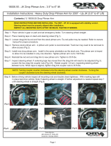
10. Hold the rear track bar bracket extension over the axle
bracket positioned as show in Figure 1. Using one of
the bolts (1/2” x 3” nc) and the spacer (1.5” x 1”OD
x .5”ID) insert them in the hole vacated by the Torx
headed bolt. Use the spacer to ll the spot the track
bar once occupied. This will keep the bracket from
Rear Installation (rst)
Figure 1

Revised 22 Dec 05
Revised 22 Dec 05
collapsing when the new bolt is tightened.
11. With the track bar bracket in place, the two (2) smaller
holes in the bracket should line up close to the holes
in the axle bracket vacated by the plastic shield
removed in Step 8.
12. Using a 5/16” drill bit, drill out the small holes upper
and lower to make room for installing the (5/16” x 1”)
bolts and nuts and washers. Install and tighten the
bolts and nuts.
13. Line up the track bar with the upper holes in the new
track bar bracket and use the Torx bolt and nut you
removed in Step 9 to secure the bar in place.
14. Install the new TeraFlex rear springs (6.50” OD).
15. Install the replacement shocks. When using the
Doetsch Tech MV series shocks, mount the shock with
the canister up for improved clearance on the axle
housing. Do not mount other brands upside down.
16. Install the new longer sway bar links using two rubber
bushings on each end of the link. Reuse the bolts you
took out of the stock links to install the new longer
ones. Push the plastic sleeve over the shank of each
bolt. Insert the bolt with sleeve into the bushings in
the link ends. Use one of the (1/2” SAE) at washers
between the sway bar and the rubber bushing. This
will cause the bushing to compress more. Using the
nut you removed, tighten the sway bar links into
place.
Rear Installation Complete.
1. Jack up the front of the TJ by the frame and set stands
in place.
2. Remove the front tires and front shocks. Remember to
save those lower bolts.
3. Disconnect the lower end of the front sway bar link to
allow the front axle to drop.
4. Remove the spring clamp and bolt and set aside.
5. Remove the front springs. Passenger side rst.
6. Remove the bump stop cushions and the bolts in the
bump stop cup.
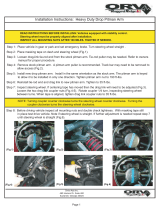
7. Using an electric hand drill and a 5/16” drill bit, locate
the center of the front, lower spring pad. The divot in
the center works well as a guide. Drill a hole through
the guide in the pad as shown in Figure 2.
8. Using the aluminum spacer as a guide, screw one of the
self-tapping bolts (3/8” x 2”) into each hole to cut
the threads and then remove the bolt and set aside.
Note: 2003 and newer TJ’s have a thick plate here. You will
need to drill and tap this with a thread tap. The self
tapping bolts won’t cut threads in the heavy plate.
9. Install the front TeraFlex springs. Right side rst.
Front Installation (second)
Set the aluminum spacer (3”OD) inside the TeraFlex
spring as you put it up into place. Once the spring is
in place, rotate the spring so the bottom end of the
spring butts up against the stop in the axle pad sup-
port.
10. Replace the spring clamp and bolt taken out in Step 4.
11. Replace the upper bump stop cup, bolt and cushion
removed in Step 6.
12. Install the front shocks. Put the tires and wheels back
on.
13. Remove the stock pitman arm from the drag link and
the steering gear. You will most likely need a pitman
arm puller. We recommend renting a good one from a
tool rental place rather than buying a cheap one.
14. Install the new TeraFlex drop pitman arm.
NOTE: The 3T DOES NOT include the drop pitman arm.
Do NOT connect the drag link yet.
15. Straightening the steering wheel
Our goal is to nd the neutral location for the front axle.
If we do this, the steering wheel will be very close to
center.
Make sure the Jeep is on at, level ground. Remove the
passenger side (right side) of the front track bar. With the
Jeep on the ground and the steering wheel locked in its
center position bounce the Jeep up and down. Use the
front bumper to do this. After you have done this the front
suspensions and steering should be in a neutral position.
Without moving any other components raise the lower
end of the track bar up into its mounting bracket. Using
the track bar center hole as a guide mark the bracket.
If you have room in the bracket so the hole does not
Figure 2 Figure 3

Revised 22 Dec 05
Revised 22 Dec 05
overlap the edges go ahead and drill the hole out. Make
sure you are drilling at a right angle to the bracket when
drilling through to the rear half of the bracket. Use a 13/
32” drill bit. If you drilled the hole in the correct location
you should be able to just lift the bar up and insert the
new 10mm x 75 mm bolt.
If there is not enough room to re-drill the track bar
mount then an adjustable front track bar must be pur-
chased. An adjustable track bar will allow you to ne tune
the correct length needed to center the axle underneath
the vehicle.
You should now connect the drag link to the drop pitman
arm.
Transfer Case Lowering Kit Installation
Drill the front track bar bracket to remount the
track bar in the position that will center the axle
underneath the vehicle.
Adjust here
1997-2002 TJ Wrangler
Applications
2003-Current TJ Wrangler
Applications
1" Spacer
Beveled washer
Lock washer
1/2"x3" bolt
1" Spacer
Lock washer
Flat washer
12mmx70mm bolt
Transfer Case Skid Plate
1. 1997-2002 TJ Wranglers- Install the six spacers
(1.25”OD x 1.25” tall) between the frame and the
cross member with the at end of the spacer up
against the frame. The 1/2” lock washer goes onto
the 1/2” x 3” bolt rst followed by the tapered washer
with the at end of the tapered washer against the
lockwasher.
2. Put the tires and wheels back on if needed and lower
the TJ to the ground.
1. 2003-current TJ Wranglers- Install the six spacers
(1.25”OD x 1.25” tall) between the frame and the
cross member with the at end of the spacer up
against the frame. The 1/2” lock washer goes onto
the M12 x 1.75 x 70 bolt rst followed by the 1/2”
at washer.
2. Put the tires and wheels back on if needed and lower
the TJ to the ground.
Fine tuning the steering:
Adjust the sleeve on the front drag link by loosening the
clamps and twisting the sleeve in a direction that causes
drag link to become shorter. Find a place you can drive
that is at and straight. Adjust the sleeve and test drive
the TJ until your steering wheel is centered to your satis-
faction and tighten the adjuster sleeve clamps.
Note: If your Jeep is not level when you put it back on the
ground, loosen all bolts and retighten with the Jeep on
the ground.
Troubleshooting
Driveline vibration
This section applies if the stock driveshaft is used. If a CV
style driveshaft is installed this section will not apply.
Acceleration vibration - The vibration is caused by the
pinion angle being to high in relation to the transfer case
output shaft.
Deceleration vibration - This vibration is caused by the
pinion angle being too low in relation to the transfer case
output shaft.

Revised 22 Dec 05
Relocator Plate
Note: 99 percent of the lifts don’t require the relocator
plate. You do not need to install this plate if-
1. You are not using the transfer case lowering kit.
2. Your transfer case shifts ne into 4 Low.
The relocator plate is no longer included in the kit. Please
call us if you are having problems shifting into 4 Low.
If you have any questions or problems with this suspen-
sion kit, contact your local dealer or contact us at Tera
Manufacturing.
Use the relocating plate to lower the pivot bearing as
shown on the body side of the shift bellcrank.
Optional Accessories Available-
Alignment notes
Suspension System Kit (part #ST)
includes front/rear lower exarms, steering box skidplate,
and sway bar disconnects.
TeraFlex FlexArms
front/rear lower exarms (part #FATJ)
front upper control arms (part# FAFU)
rear upper control arms (part# FARU)
Steering Box Skidplate (part #SBSPT)
Sway Bar Disconnects (part #QDFT)
ADJUSTMENT RANGEPREFERRED
Caster
Camber (fixed angle)
Wheel Toe-In
Thrust Angle
7
-2.5
.15
0
+/- 1.0
+/- 0.63
+/- 0.15
+/- 0.15
After installation of the TeraFlex suspension kit, it
is imperative that the front end alignment angles be
checked. It is recommended that your TJ be taken to a
reputable alignment shop that understands 4WD vehicles
and has experience with their alignment parameters.
There are three basic alignment angles: camber, caster,
and toe-in. Camber is pre-set by the manufacturer and
cannot be adjusted. If the camber angle is off, this could
indicate that something is bent.
Caster might be changed with the installation of our
suspension kit. It is recommended that the factory speci-
cations be maintained. If this cannot be obtained with the
caster adjustment eccentrics found on the lower control
arms, you may opt for our FlexArms (exible lower control
arms) which allow for additional adjustment.
Toe-in is also important for tire wear. Toe-in may be
affected on a three-inch kit, and will be affected on a
four-inch kit. It has been recommended that the toe-in
be set to minimum factory specications if you go to the
larger tire and wheel set up.
.
If you have constant vibration when accelerating or
decelerating, see which of these actions causes the vibra-
tion to decrease in severity. If you accelerate and the
vibration diminishes you need to bring the yoke up.
Because the axle is mounted in rubber, the axle will
rotate in the rubber under torque. TeraFlex has lower and
upper control arms available which are adjustable. With
the FlexArms from TeraFlex, you can adjust your pinion
angles to eliminate vibration.
Factory Alignment Specications
/