Page is loading ...

Doc.Ref. No. m104/QG/101 Issue No.:07 Page 1 of 2
AUTO TUNE PID CONTROLLER
SPECIFICATION
Input type
Temp. RangeºC
Input
type
Temp.
RangeºC
PT100(0.1ºC)
-199.9 to 850.0
B
450 to 1800
PT100
-199 to 850
R
0 to 1768
E
-200 to 1000
S
0 to 1768
J
-200 to 1200
K
-200 to 1372
T
-200 to 400
Table-1.1
INPUT
Accuracy
T/C and RTD:
+ (0.25% of Full Span ± 1 count)
Resolution
ADC:16 bits,
Display :0.1°C / 1 Count
Sampling Rate
5 Samples/Sec
CJC Error
±3.0 °C Max
Sensor Burnout
current
0.25uA
RTD excitation current
0.166mA (Approx)
Allowable wiring
resistance for RTD
Maximum 15 ohms/wire
(Resistance between three wires
should be equal)
NMRR
> 40 dB
CMRR
> 120 dB
Temp-co
< 100ppm/°C
Input Impedance
> 1MΩ
Max Voltage
20VDC
DISPLAY
PV
Display
TC596: 0.56” 7-segment Red LED 4-Digit
TC548, TC548E: 0.4” 7-segment White LED 4-
Digit
SV
Display*
TC548E: 0.31” 7-segment Green LED 4-Digit
Status
Indication
Individual RED Led for Relay/SSR and Alarm
Status
Keys
Enter, Increment, Decrement
* For TC548E
OUTPUT
TYPE
Control
Mode
Rating
Type
Relay-1
PID/On-Off
/Alarm
10A @ 230VAC /
28VDC
Single Change
over, Three
Terminals
(C, NO, NC)
Relay-2
Alarm
5A @ 230VAC /
28VDC
SSR
PID
11VDC or more /
2VDC or less
Voltage Pulse
Output
Resolution: -
10mSec
Model
TC596
TC548
TC548E
Relay-1
Relay-2
SSR
(in lieu of relay-1)
POWER SUPPLY
Standard
85-265VAC/ 100-300VDC
Power consumption
<3 VA
ENVIRONMENTAL CONDITION
Humidity (Non-Condensing)
30% to 95% RH
Instrument Warm-up Time
Approx. 15 minutes
Ambient Temperature
0 to 55°C
Storage Temperature
0 to 80°C
PHYSICAL
Models
TC596
TC548, TC548E
Front Bezel (in mm)
100 x 100
50 x 50
Panel Cutout (in mm)
92 x 92
45 x 45
Depth Behind the Panel
(in mm)
52
70 (Including
Terminal)
Weight (Approx.)
160g
110g
Enclosure Material
Lid: PC,
Base: ABS
PC
Enclosure Protection
IP20
Terminal Cable Size
Barrier type terminal,
cable 2.5 mm2
MOUNTING DETAILS
TC596: All Dimensions are in mm
TC548, TC548E: All Dimensions are in mm
WARRANTY
Warranty does not apply to defects resulting from action of
the user such as misuse, improper wiring, operation
outside of specification, improper maintenance or repair,
or unauthorized modification. Masibus is not liable for
special, indirect or consequential damages or for loss of
profit or for expenses sustained as a result of a device
malfunction, incorrect application or adjustment Masibus’
total liability is limited to repair or replacement of the
product.
The warranty set forth above is inclusive and no other
Warranty, whether written or oral, is expressed or implied.
SAFETY/WARNING PRECAUSTIONS
To ensure that the device can be operated safely and all
functions can be used, please read these instructions
carefully.
Installation and Start-up must be carried out by qualified
personnel only. The relevant county-specific regulations
must also be observed.
Before start-up it is particularly important to ensure:
Terminal wiring: check that all cables are correctly
connected according to the connection diagram
All wiring must confirm to appropriate standards of good
practice and local codes and regulations. Wiring must be
suitable for voltage, current and temperature rating of the
system. Unused control terminals should not be used as
jumper points as they may be internally connected, which
may cause damage to the unit.
LOAD CONNECTION
Electrical precautions during use: Electrical noise
generated by switching of inductive loads can create
momentary disruption, erratic display, and latch up, data
loss or permanent damage to the instrument. Use of
snubber circuits across loads as shown above, is
recommended.
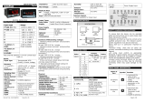
TERMINAL CONNECTION
TC596:
TC548E: TC548:
FRONT KEYS DESCRIPTION
Functions
Key press
To enter into
Set-point mode
Press key to entering into Set-
point mode.
Set-point is changed by using
or Keys. Then Press Key to
Store the Set-point.
To enter into
lock mode
Press & Keys for 3 seconds
to enter into Lock mode.
To enter in to
run mode
Press & Keys to enter into
Run mode from menu mode.
FRONT PANEL DESCRIPTION
Symbol
Function
In run mode Press Increment key to view
ambient temperature. In run mode press
Increment key for 3 seconds to entering into
conf mode. In Menu mode it increments the
value of any parameters.
In run mode Press Decrement key to view
average energy. In run mode press
Decrement key for 3 seconds to entering
into tune mode. In Menu mode it
decrements the value of any parameters.
In run mode Press enter key to entering in
to set-point mode. In menu mode it stores
the value of parameters. TC548E: In run
mode press enter key for 3 seconds to view
remaining soak time.
PV
Display Process Value. Display parameter
name when user set parameter.
R1,R2,R3
ON when Relay is energized & OFF
otherwise.
PARAMETER SETTINGS
Display
Name
Description
Def
ault
Valu
e
Shows
only if
C1.SP
(C1.sp)
Control
Set Point
1
Range Depending on
PV sensor type
selected
100
-
A1.SP
(A1.sp)
Alarm
Set Point
1
Range Depending on
PV sensor type
selected
100
TC548E,
SSR is
selected
in OT.
A2.SP
(A2.sp)
Alarm
Set Point
2
Range Depending on
PV sensor type
selected
100
TC548E
SSTR*
(SSRT)
SOAK
run/stop
Run/ Stop button for
SOAK.
st o
p
TC548E
** L a s t d e c i m a l p o i n t o f P V d i s p l a y “ O N ” , i n d i c a t e s R U N .
Tune mode
A.TUN
(A.tun)
Auto
Tune
Auto Tuning Process
yes / no
NO
COP is
PID
PB
(pb)
Proportio
nal Band
0 to 9999(B,R,S,RTD 1
deg0C) or 0.0 to 999.9
(E,J,K,T,RTD 0.1
deg0C)
160
.0
COP is
PID
TI
(ti)
Integral
Time
0 to 1000
175
COP is
PID
TD
(td)
Derivativ
e Time
0 to 180
40
COP is
PID
CT
(Ct)
Cycle
Time
Adjust Cycle Time
1 – 300 sec
10
CO P is
PI D
MR
(mr)
Manual
Reset
To Prevent Overshoot
(-50% to +50%)
of PB
-40%
COP is
PID
TIL
(til)
Integral
Inihibit
Low
0 to 100
100
COP is
PID
O.DIR
(o.dir)
Output
Direction
Reverse/Direct
0
( R E
V)
COP is
PID
RAMP
(rAMP)
Ramp
Rate
Type
None/minutes/hours
NO
NE
TC548E
RMPR
(rMPr)
Ramp
rate
Value
0.1 to 999.9 Degree
per minute or hour
0 . 1
TC548E
SOKR
(Sokr)
Soak
Rate
0 to 99.59
[HH.MM]hour and
minute
0 . 0
0
TC548E
SOKT
(Sokt)
Soak
Type
Reset/Hold
R E S
ET
TC548E
Conf Mode
INPT
(inpt)
INPUT
Type
As per table 1.1
TC E
ZERO
(zero)
Zero
Any value within the
Input Range & less the
SPAN Value.
-200
If TC E
SPAN
(span)
Span
Any value within the
Input Range & greater
the ZERO Value.
100
0
If TC E
DP
(dp)
Decimal
Point
1/ 0.1
1
*FLTR
(fltr)
Filter
Filter for PV Input(0 to
5)
3
OFST
(OFST)
Offset
Offset to be added in
PV value -100.0 to
100.0
0
OPES
(opes)
OPEN
Sensor
Status
Set Control O/P when
Input OPEN condition.
DOWN /UP
UP
OT
(oT)
Output
Type
Relay/SSR
Rely / SSR
R e l
ay
TC548,
TC548E
Model
COP
(Cop)
Control
Output
PID/ONOF
pid / onof
PID
Type
OT
is Relay
Quick User Guide
TC596, TC548, TC548E

Doc.Ref. No. m104/QG/101 Issue No.:07 Page 2 of 2
Type
TSP
(tsp)
Type of
Set Point
L-ON / H-ON
Lower ON
Higher ON
L-
ON
Control
Type (COP)
is ON-OFF
HY
(Hy])
Hysteresi
s
Hysteresis Value (in
°C) for Relay during
ON-OFF type Control.
1 to 250
1
Control
Type (COP)
is ON-OFF
RD1
(rd1)
Relay
Delay
(For
Relay-1)
Relay Delay is amount
of time (in sec), that
Relay will wait before
getting ON after the
ON condition occurs.
1 to 99 sec
1
sec
TC548,
TC548E
Model
DISP
(disp)
Display
Set Point
Set which Set Point to
shown in SV display in
RUN mode while
device is in Auto Mode
C1.SP, A2.SP Tsok
(Remaining Soak time)
0
TC548,
TC548E
Model
CO.LO
(Co.Lo)
Control
Output
Low
Control Output Low
Limit in %. 0.0 to
100.0 %
(CO.LO < CO.HI)
0 . 0
TC548,
TC548E
Model
CO.HI
(Co.Hi)
Control
Output
High
Control Output High
Limit in %.
0.0 to 100.0 %
100
.0
TC548,
TC548E
Model
A1TP
(a1tp)
Alarm
Type – 1
Refer ALARM Type
Table
0 to 15
6
(PV.
A.L)
TC548,
TC548E,
SSR is
selected in
OT.
A1HY
(a1Hy)
Alarm 1
Hysteresi
s
Set Hysteresis (in °C)
for Alarm-1
1
A1LC
(a1lC)
Alarm 1
Logic
Set Logic for Alarm-1
0: NORM (Normal)
1: FLSF (Fail-Safe)
0
(Nor
mal)
A1DY
(a1.Dy)
Alarm 1
Delay
Alarm Delay is amount
of time (in sec), that
Relay-1 will wait
before getting ON after
the alarm condition
occurs.
1 to 99 sec
1
A2TP
(a2tp)
Alarm
Type – 2
Refer ALARM Type
Table
0 to 15
6
(PV.
A.L)
TC548E
Model
A2HY
(a2Hy)
Alarm 2
Hysteresi
s
Set Hysteresis (in °C)
for Alarm-2
1
TC548E
Model
A2LC
(a2lC)
Alarm 2
Logic
Set Logic for Alarm-2
0: NORM (Normal)
1: FLSF (Fail-Safe)
0
(Nor
mal)
TC548E
Model
A2DY
(a2.Dy)
Alarm 2
Delay
Alarm Delay is amount
of time (in sec), that
Relay-2 will wait
before getting ON after
the alarm condition
occurs.
1 to 99 sec
1
TC548E
Model
A.CJC
(a.CJC)
ACJC
Auto Cold Junction
Compensa-tion
NO / yes
YES
Input Type
is TC.
F.CJC
(F.CJC)
Fix cold
junction
Compens
a-tion
0 to 60.0 °C
0.0
Input Type
is TC &
A.CJC is
NO.
PASS
(pass)
Password
Password protection
for calibration mode &
factory default
1
VERS
(vers)
Version
Shows the Version of
the Current Firmware
-
*The value of FLTR will determine the ability of filtering noise. When a large
value is set, the measurement input is stabilized but the response speed is
slow. “FLTR” should be set to 0 or 1 to short the response time.
Lock Mode : To lock/Unlock
L.CON
(L.CON)
The conf menu
parameters
lock/
unlock
Unlock
L.TUN
(L.TUN)
the tune menu
parameters
L.SC1
(L.SC1)
the Control Set
point
L.SA1
(L.SA1)
the Alarm -1 set
point
TC548,
TC548E,
OT is SSR
L.SA2
(L.SA2)
the Alarm -2 set
point
TC548E
L.Str
(L.STR)
the Run/ Stop
button for SOAK.
TC548E
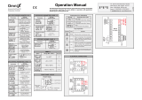
CONTROL FUNCTION
ON/OFF Control (For L-ON Mode): The relay is ‘ON’ up to the
set temperature and cuts ‘OFF’ above the set temperature. As the
temperature of the system drops, the relay is switched ‘ON’ at a
temperature slightly lower than the set point.
L-ON H-ON
Figure 1.1: Typical Relay operation
HYSTERESIS: The difference between the temperatures at which
relay switches ‘ON’ and at which the relay switches ‘OFF’ is the
hysteresis or dead band.
PID Control
Auto Tuning: The Auto tuning process is performed at set point.
Temperature will oscillate around the set point during tuning
process. Set a set point to a lower value if overshooting around
the normal process value is likely to cause damage. To start the
auto tuning process, set the desired set point, select the
parameter A.TUN in TUNE menu and set it to YES. During Auto
tuning lower display (SV) will flash “AT” message. After auto tune
procedure is completed, the message will be removed and
controller will revert back to the PID control by using the new
calculated PID values. The PID values obtained are stored in the
nonvolatile memory.
AUTO TUNE FUNCTION:
Manual Reset: After some time, the process temperature settles
at some point and there is a difference between the set
temperature & the controlled temperature. This difference can be
removed by setting the manual reset value equal & opposite to
the offset. Range for the manual reset is -50.0% to +50.0% of
proportional band.
Cycle Time: The Cycle time for output is the time where the
output is on for percentage of that time and off for a percentage
of that time, creating a portioning effect. The cycle time is only
used where PI, PD or PID control action is used. The shorter the
cycle time, the higher the proportionate resolution is, and better is
the control.
For Relay output: Set to 10 to 300 seconds or more
For SSR output: Set to 1 to 60 seconds or more
USER GUIDE
PV bias for input correction: PV bias is used for normal
operation. This function can be used for adjustment to
compensate for differences in measurement reading.
Settable Digital Filter: In certain application the process value is
too unstable to be read. To improve this, a programmable low
pass filter incorporated in the controller can be used. This is a first
order IIR filter with time constant.
Filter Effects:
Input PV Filtering for 2 sec Filtering for 10 sec
Settable manual reset to prevent overshoot: Virtually no
process requires precisely 50% output on single output controls or
0% output on two output controls. Because of this many older
control designs incorporated an adjustment called manual reset
(also called offset on some controls). This adjustment allows the
user to redefine the output requirement at the set point. A
proportioning control without manual reset or Integral time will
settle out somewhere within the proportioning band but likely not
on the set point.
Some controls use manual reset (as a digital user programmable
value),this allows the user to pre-program the approximate output
requirement at the set point to allow for quicker settling at set
point when Automatic reset (Integral time) set to zero.
For PI and PID control, set MR to prevent overshoot
Range for the manual reset is -50% to +50% of Proportional
band.
Integral Inhibit: The Value of Integral Inhibit is in a percentage of
PB.
To accurate control a process at some defined set point we use
PID control. But some of the processes, overshoot can occur
during controlling. To overcome this type of issue we can use
Integral Inhibit parameter in such type of process to control
overshoot.
By use of integral inhibit “I” term (Integral constant) function is
limited in specific region of Proportional band (PB).
ALARM OUTPUT
Alarm Types:
Various alarm operations are shown in the reference figure.
Display
message
ALARM
TYPE
Display
message
ALARM TYPE
1
none
None
9
SP.A.L
Absolute value
set point low
alarm
2
Pv.d.H
Deviation
High alarm
10
P.S.d.H
Deviation High
alarm with
standby
3
Pv.d.l
Deviation
Low alarm
11
P.S.d.L
Deviation Low
alarm with
standby
4
Pv.d.r
Deviation
High & Low
range
alarm
12
P.S.d.r
Deviation High
& Low range
alarm with
standby
5
Pv.d.b
Deviation
High & Low
Band
alarm
13
P.S.d.b
Deviation High
& Low limit
alarm with
standby
6
Pv.a.H
Absolute
value High
alarm
14
P.S.A.H
Absolute value
High alarm
with standby
7
Pv.A.L
Absolute
value Low
alarm
15
P.S.A.L
Absolute value
Low alarm
with standby
8
SP.A.H
Absolute
value set
point high
alarm
16
PV.-E.
PV error
(OPEN/OVER/
UNDER)
NOTE-1: The fault diagnosis output turns on in case of input burnout (PV)
failure.
NOTE: -
LIT = LED on, UNLIT = LED off
Up arrow indicate Alarm will ON from this value.
Down arrow indicate Alarm will OFF from this value.
Standby operation:
For alarm types, 9 to 14, the relay action happens only after the
PV has crossed the SP after power on.
For operation manual please visit www.masibus.com
Specifications are subject to change without notice due to
Continuous improvements.
Masibus Automation And Instrumentation Pvt. Ltd.
B-30, GIDC Electronics Estate, Sector-25, Gandhinagar-
382044, Gujarat, India.
Tel: +91 79 23287275-77 Fax: +91 79 23287281
Web:www.masibus.com Email:support@masibus.com
/