Page is loading ...

Doc.Ref. No. m61D/QG/101 Issue No.:01 Page 1 of 2
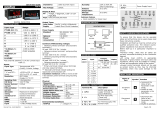
FLAMEPROOF AUTO-TUNE PID CONTROLLER
LC5296-XP-AT can be configured as PID or ON-OFF
Controller
SPECIFICATIONS
Input
type
Range
Input
type
Range
PT100
(0.1ºC)
-199.9 to 850.0 ºC
B
450 to 1820°C
R
0 to 1768ºC
PT100
(1ºC)
-200 to 850ºC
S
0 to 1768ºC
*4-20mA
/1-5VDC
-1999 to 9999
(Field Scalable)
E
-200 to 1000ºC
J
-199.9 to 1200ºC
*0-20mA
/0-5VDC
K
-199.9 to 1372ºC
T
-199.9 to 400ºC
0-10VDC
*Use external 250ohms, 0.1% for current Input
Table 1.1
Inputs
Accuracy
T/C and RTD :
Linear :
+ (0.25% of Full Span ± 1 count)
+ (0.1% of Full Span ± 1 count)
Resolution
ADC: 16 bits, Display : 0.1°C/1 Count
Sampling Rate
5 Samples/Sec
CJC Error
±2.0 °C Max
Sensor Burnout
current
0.25uA
RTD excitation
current
0.166mA (Approx.)
Allowable wiring
resistance for
RTD
Maximum 15 ohms/wire (Conductor
resistance between three wires should
be equal)
NMRR
> 40 dB
CMRR
> 120 dB
Input
Impedance
> 1MΩ (Voltage Input),
250Ω Current Input)
Max Voltage
20VDC
Display & Keys
PV Display
4-Digit, 7-Segment, 0.56” High, Red
SV Display
4-Digit, 7-Segment, 0.40” High, Green
Status
Indication
Individual RED Led for Relay, SSR, Manual
& Communication Status
Keys
Auto manual, Enter, Decrease, Increase
Output Types
Relay
Output
Relay-1: For PID or ON-OFF Controlling.
Used as Alarm-1 Output(Output Type is Linear)
Relay-2: Alarm-2 Output
SSR
Output
Voltage Pulse Output
Available at Terminals of Relay-1
Linear
Available at Terminals of Retransmission-1. Linear
Output
Output Type as per selection in Retransmission-1
Output Type.
At a time unit can support Relay or SSR Output. (Factory settable)
Relay Output
Type
Single Change over Three Terminals (C, NO, NC)
Rating
5A @ 230VAC / 30VDC
Pulse Output (SSR)
Output
signal
Voltage Pulse Output, On/Off-condition
11VDC or more / 2VDC or less
Resolution
10 ms
Linear Output
Output
Signal
Voltage (0-5VDC, 1-5VDC, 0-10VDC)@3kΩMin
Current (4-20mADC, 0-20mADC)@500ΩMax
Retransmission Output
Number of output
Linear Output Type
Relay/SSR Output Type
1 (@Retransmission-2)or
2 (@Retransmisswion-1&2)
Output According to
Process Value
Output Signal
4-20mA/ 0-20mA/1-5VDC/ 0-
5VDC / 0-10V DC
Load resistance
For Current o/p
For Voltage o/p
<500Ω
>3KΩ
Output accuracy
±0.25% of span
Alarm Output
Number of
Outputs
2 if Output Type is Linear(@Relay-1&2),
1 if Output Type is Relay or SSR(@Relay-2)
Control relays are available as alarm outputs
Type
Three terminals (NC, NO, and C)
Rating
250 V AC or 30 V DC, 5A (resistive load)
Loop Power Supply
Supply Voltage
24VDC (±10%) @26mA
Communication Details
Communication
Interface
RS485 (2 Wire)
Protocol
Modbus-RTU
Baud rate
9600, 19200, 38400 bps
Physical
Dimension (H x W x D) mm
IIA & IIB
IIA , IIB & IIC
150 x 150 x 120
180 x 165 x 140
Weight (Approx.)
IIA & IIB
IIA , IIB & IIC
2.6kg
3.1kg
Enclosure Material
Flameproof
(Explosion Proof) Ex-d
Enclosure Protection
IP 66
Gas Groups
IIA, IIB,
IIC (optional)
Area Classification
Zone 1 & 2
Environmental Conditions
TEMPCO
Input to PV Display
Display to RX and Control output
< 100ppm/oC
< 100ppm/oC
Humidity
30% to 95% RH
(Non-Condensing)
Instrument Warm-up Time
Approx. 15 minutes
Ambient temperature
0 to 55°C
Storage Temperature
0 to 80°C
Power Supply
Standard
85-265VAC/ 100-300VDC
Optional
18-36VDC
Power consumption
<10 VA
Data backup
Non-volatile memory (can be
written up to 100000 times)
Isolation (Withstanding voltage)
Between primary terminals* and secondary terminals**:
At least 1500 V AC for 1 minute
Between primary terminals* and grounding terminal:
At least 1500 V AC for 1 minute
Between grounding terminal and secondary terminals**:
At least 1500 V AC for 1 minute
Between secondary terminals**:
At least 500 V AC for 1 minute
* Primary terminals indicate power terminals and relay output
terminals.
** Secondary terminals indicate analog I/O signal and
Communication O/P.
Insulation resistance: 20MΩ or more at 500 V DC between
power terminals and grounding terminal.
SAFETY/WARNING PRECAUSTIONS
To ensure that the device can be operated safely and all
functions can be used, please read these instructions carefully.
Installation and Start-up must be carried out by qualified
personnel only. The relevant county-specific regulations must
also be observed.
Before start-up it is particularly important to ensure:
Terminal wiring: check that all cables are correctly connected
according to the connection diagram
All wiring must confirm to appropriate standards of good
practice and local codes and regulations. Wiring must be
suitable for voltage, current and temperature rating of the
system.
Unused control terminals should not be used as jumper
points as they may be internally connected, which may cause
damage to the unit.
TERMINAL CONNECTION
Terminal No.
Description
1 C2
2 NO2
3 NC2
For Relay-1 potential free Contacts
Terminal 4,5:- SSR Pulse o/p.
4 C1
5 NO1
6 NC1
For Relay-2 potential free Contacts
Alarm-2 o/p.
7 Earth
Earth Connection
8 N/-
9 L/+
Power Supply Input
10 C+
For RTD Input (3-wire Compensation)
11 TC+/V+
12 TC-/V-/LPS-
For Thermocouple, RTD & Linear Input
13 LPS+
24VDC Loop power supply
14 C+
For RTD Input (3-wire Compensation)
15 TC+/V+
For Thermocouple, RTD & Linear Input
16 TC-/V-/LPS-
17 Linear O/P
+/RTR1+
18 Linear O/P
-/RTR1-
For Retransmission-1 output
Linear type Control Output
19 D+/ RTR2+
20 D- / RTR2-
For Retransmission-2 output OR
Modbus-RTU Communication Output
LOAD CONNECTION
Electrical precautions during use
Electrical noise generated by switching of inductive loads can
create momentary disruption, erratic display, latch up, data
loss or permanent damage to the instrument. Use of snubber
circuits across loads as shown above, is recommended.
FRONT PANEL DESCRIPTION
Symbol
Function
Increment the Value of any Parameter. Shows
ambient value for T/C Input in RUN mode. In
Manual Mode this key is used to Increment the
%Power.
Decrement the Value of any Parameter. Shows
%Power value if Device is in Auto Mode in RUN
mode. In Manual Mode this key is used to
Decrement the %Power.
In Sub Menu it can be used to get to the next
Parameter. It is also used to save the parameters to
nonvolatile memory, for parameter configuration. In
RUN mode it shows different set point.
Get to the Previous Menu level.
It is used to switch between Auto to Manual mode
and Manual to Auto mode if pressed for at least 2
sec if function key is A/M. Shows remaining soak
time when pressed if function key is selected SOK.T.
PV
Display process value. Display parameter name
when user set parameter. Display error message
when an error occurs.
SV
Display set value. Display parameter value of
parameter in process value field when user set
parameter. Display control output value when in
manual mode.
RL1
ON when Relay-1 is energized & OFF otherwise.
RL2
ON when Relay-2 is energized & OFF otherwise.
SSR
SSR ON status.
MAN
ON when unit is in Manual mode, Off Otherwise.
Tx
ON when device is transmitting Data (RS-485).
Rx
ON when device is receiving Data (RS-485).
Quick User Guide
L
LC
C5
52
29
96
6-
-X
XP
P-
-A
AT
T

Doc.Ref. No. m61D/QG/101 Issue No.:01 Page 2 of 2
CONTROL FUNCTION
ON/OFF Control (For L-ON Mode): The relay is „ON‟ up to the
set temperature and cuts „OFF‟ above the set temperature. As the
temperature of the system drops, the relay is switched „ON‟ at a
temperature slightly lower than the set point.
L-ON H-ON
Figure 1.1: Typical Relay operation
HYSTERESIS: The difference between the temperatures at which
relay switches „ON‟ and at which the relay switches „OFF‟ is the
hysteresis or dead band.
PID Control
Auto Tuning: The Auto tuning process is performed at set point.
Temperature will oscillate around the set point during tuning
process. Set a set point to a lower value if overshooting around
the normal process value is likely to cause damage. To start the
auto tuning process, set the desired set point, select the
parameter A.TUN in TUNE menu and set it to YES. During Auto
tuning lower display (SV) will flash “AT” message. After auto tune
procedure is completed, the message will be removed and
controller will revert back to the PID control by using the new
calculated PID values. The PID values obtained are stored in the
non-volatile memory.
AUTO TUNE FUNCTION:
Manual Reset: After some time the process temperature settles at some
point and there is a difference between the set temperature & the
controlled temperature. This difference can be removed by setting
the manual reset value equal & opposite to the offset. Range for
the manual reset is -50.0% to +50.0% of proportional band.
Cycle Time: The Cycle time for output is the time where the
output is on for percentage of that time and off for a percentage of
that time, creating a portioning effect. The cycle time is only used
where PI, PD or PID control action is used. The shorter the cycle
time, the higher the proportionate resolution is, and better is the
control.
For Relay output: Set to 10 to 300 seconds or more
For SSR output: Set to 1 to 60 seconds or more
Ramp and Soak Function:
This function is used to stop the sudden change of set point. The
ramp function is performed in following conditions. The target set
point is changed. Target set point number is changed. The power
is turned ON or the controller is recovered from power failure. A
change is made from manual mode to auto mode. When the process
value crosses the set point value for the first instant, a “soak period” begins.
The ramp function will be performed when ramp unit parameter is
selected as MInR(minute rate) or HRR (hour rate). The ramp rate
can be programmed by setting the parameter rmp.r. The Soak
rate is programmed by setting sok.r. Soak time will be performed
according to s.hod and s.rst. When the soak type is s.hod it will
not reset the soak rate when the power is down and when the
Soak type is s.rst it will reset the soak rate when the power is
down.
The ramp and Soak function will be cancelled in following
conditions.
A change is made from Auto mode to manual mode.
Sensor Failure occurs.
Auto tuning function is activated.
ALARM OUTPUT
Alarm Types:
Various alarm operations are shown in the reference figure.
Display
message
ALARM TYPE
Display
message
ALARM TYPE
none
None
SP.A.L
Absolute value set
point low alarm
Pv.d.H
Deviation High
alarm
P.S.d.H
Deviation High
alarm with standby
Pv.d.l
Deviation Low
alarm
P.S.d.L
Deviation Low
alarm with
standby
Pv.d.r
Deviation High
& Low range
alarm
P.S.d.r
Deviation High &
Low range alarm
with standby
Pv.d.b
Deviation High
& Low Band
alarm
P.S.d.b
Deviation High &
Low limit alarm
with standby
Pv.a.H
Absolute value
High alarm
P.S.A.H
Absolute value
High alarm with
standby
Pv.A.L
Absolute value
Low alarm
P.S.A.L
Absolute value Low
alarm with standby
SP.A.H
Absolute value
set point high
alarm
PV.-E.
PV error (OPEN
/OVER/UNDER)
Note: The fault diagnosis output turns on in case of input
burnout (PV) failure.
NOTE:-
LIT = LED on, UNLIT = LED off
Up arrow indicate Alarm will ON from this value.
Down arrow indicate Alarm will OFF from this value
MENU LAYOUT For LC5296-XP-AT
ORDERING CODE
Model
Input
Power Supply
Control Output
Option
Gas Group
1 (AO1*)
2 (AO2** or
RS485)
LC5296-XP
-AT
1
E
U1
85-265VAC/
100300VDC
1
Relay
N
None
N
None
1
IIA & IIB
2
J
2
SSR
1
4-20 mA
1
4-20 mA
2
IIA, IIB &
IIC
3
K
U2
18-36VDC
2
0-20 mA
2
0-20 mA
4
T
3
1-5V
3
1-5V
5
B
4
0-5V
4
0-5V
6
R
5
0-10V
5
0-10V
7
S
*Configurable as MV or PV
6
RS-485
9
Pt-100
** PV only
C
4-20mA
For operation manual please visit www.masibus.com
Specifications are subject to change without notice due
to continuous improvements.
Masibus Automation And Instrumentation Pvt. Ltd.
B-30, GIDC Electronics Estate, Sector-25, Gandhinagar-
382044, Gujarat, India.
Tel:+91 79 23287275-79 Fax: +91 79 23287281
Web:www.masibus.com Email:[email protected]
D
0-20mA
E
1-5V
F
0-5V
G
0 -10V
/