Page is loading ...

i
Installation & Operation Manual
3400 1/32 DIN
Automatic Tuning Smarter
Logic Temperature Controller
PK545
0037-75576
April 2018

ii
Warning Symbol
This Symbol calls attention to an operating procedure
or practice which if not correctly performed or adhered
to, could result in severe personal injury or damage to
the product or system.
Do not proceed beyond a warning symbol until the in-
dicated conditions are fully understood and met.
FM approved high limit controllers should always be
used in heated systems.
Manual Use
Installers ................................................... Chapter 1, 2
Basic Function User ............................. Chapter 1, 3, 5
Enhanced Function User .................. Chapter 1, 3, 4, 5
System Designer .......................................All Chapters
Expert User ......................................................Page 11
Safety and Warranty Information
Warranty and Returns Statement
These products are sold by Chromalox under the war-
ranties set forth in the following paragraphs. Such war-
ranties are extended only with respect to a purchase
of these products, as new merchandise, directly from
Chromalox or from a Chromalox distributor, repre-
sentative or reseller and are extended only to the first
buyer thereof who purchases them other than for the
purpose of resale.
Warranty
These products are warranted to be free from function-
al defects in material and workmanship at the time the
products leave Chromalox factory and to conform at
that time to the specifications set forth in the relevant C
instruction manuals sheet or sheets, for such products
for a period of three years.
THERE ARE NO EXPRESSED OR IMPLIED WAR-
RANTIES, WHICH EXTEND BEYOND THE WAR-
RANTIES HEREIN AND ABOVE SET FORTH.
CHROMALOX MAKES NO WARRANTY OF MER-
CHANTABILITY OR FITNESS FOR A PARTICULAR
PURPOSE WITH RESPECT TO THE PRODUCTS.
Limitations
Chromalox shall not be liable for any incidental damag-
es, consequential damages, special damages, or any
other damages, costs or expenses excepting only the
cost or expense of repair or replacement as described
above. Products must be installed and maintained in
accordance with Chromalox instructions. There is no
warranty against damage to the product resulting from
corrosion. Users are responsible for the suitability of
the products to their application.
For a valid warranty claim, the product must be re-
turned carriage paid to the supplier within the war-
ranty period. The product must be properly packaged
to avoid damage from electrostatic discharge or other
forms of harm during transit.

iii
Table of Contents
Contents Page Number
Safety & Warranty ................................................................................................................................................... ii
Chapter 1 Overview ................................................................................................................................................ 1
1-1 Features ....................................................................................................................................................... 1
1-2 Ordering Code ............................................................................................................................................. 3
1-3 ProgrammingPort andDIP Switch ............................................................................................................... 4
1-4 Keys and Displays ....................................................................................................................................... 5
1-5 Menu Overview ............................................................................................................................................ 7
1-6 System Modes ............................................................................................................................................. 8
1-7 Parameter Descriptions ............................................................................................................................... 9
Chapter 2 Installation ........................................................................................................................................... 17
2-1 Unpacking ................................................................................................................................................. 17
2-2 Mounting ................................................................................................................................................... 17
2-3 Wiring Precautions .................................................................................................................................... 18
2-4 Power Wiring ............................................................................................................................................. 18
2-5 Sensor Installation Guidelines ................................................................................................................... 19
2-6 Thermocouple Input Wiring ....................................................................................................................... 19
2-7 RTD Input Wiring ....................................................................................................................................... 20
2-8 Linear DC Input Wiring .............................................................................................................................. 20
2-9 CT / Heater Current Input Wiring ............................................................................................................... 21
2-10 Event Input wiring .................................................................................................................................... 22
2-11 Output 1 Wiring ....................................................................................................................................... 22
2-12 Output 2 Wiring ....................................................................................................................................... 24
2-13 Alarm 1 Wiring ......................................................................................................................................... 25
2-14 Alarm 2 Wiring ......................................................................................................................................... 26
2-15 RS-485 .................................................................................................................................................... 27
2-16 RS-232 .................................................................................................................................................... 28
2-17 Analog Retransmission ............................................................................................................................ 29
2-18 Programming Port ................................................................................................................................... 30
Chapter 3 Programming the Basic Function ..................................................................................................... 31
3-1 Input 1 ....................................................................................................................................................... 32
3-2 OUT1 & OUT2 Types ................................................................................................................................. 33
3-3 Rearrange User Menu ............................................................................................................................... 33
3-4 Display SV Instead of PV ........................................................................................................................... 34
3-5 Heat Only Control ...................................................................................................................................... 34
3-6 Cool Only Control ...................................................................................................................................... 35
3-7 Heat - Cool Control ................................................................................................................................... 36
3-8 Dwell Timer ................................................................................................................................................ 37
3-9 Process Alarms .......................................................................................................................................... 38
3-10 Deviation Alarms ...................................................................................................................................... 40
3-11 Deviation Band Alarms ............................................................................................................................ 41
3-12 Heater Break Alarm ................................................................................................................................. 42
3-13 Loop Break Alarm .................................................................................................................................... 43
3-14 Sensor Break Alarm ................................................................................................................................. 44
3-15 SP1 Range ............................................................................................................................................... 44
3-16 PV1 Shift .................................................................................................................................................. 45
3-17 Failure Transfer ........................................................................................................................................ 46
3-18 Bumpless Transfer ................................................................................................................................... 47
3-19 Self-tuning ............................................................................................................................................... 48
3-20 Auto-tuning .............................................................................................................................................. 49
3-21 Manual Tuning ......................................................................................................................................... 51
3-22 Signal Conditioner DC Power Supply ..................................................................................................... 54
3-23 Manual Control ........................................................................................................................................ 55

iv
3-24 Display Mode ........................................................................................................................................... 55
3-25 Heater Current Monitoring ....................................................................................................................... 56
3-26 Reload Default Values ............................................................................................................................. 56
Chapter 4 Programming the Full Function ......................................................................................................... 57
4-1 Event Input ................................................................................................................................................ 57
4-2 Second Set Point ....................................................................................................................................... 58
4-3 Second PID Set ......................................................................................................................................... 58
4-4 Ramp & Dwell ............................................................................................................................................ 59
4-5 Remote Set Point ...................................................................................................................................... 60
4-6 Differential Control ..................................................................................................................................... 61
4-7 Output Power Limits .................................................................................................................................. 62
4-8 Data Communication ................................................................................................................................. 63
4-9 Analog Retransmission .............................................................................................................................. 64
4-10 Digital Filter .............................................................................................................................................. 65
4-11 Sleep Mode ............................................................................................................................................. 65
4-12 Pump Control .......................................................................................................................................... 66
4-13 Remote Lockout ...................................................................................................................................... 67
Chapter 5 Applications ........................................................................................................................................ 68
5-1 Pump / Pressure Control ........................................................................................................................... 68
5-2 Variable Period Full Wave SSR ( VPFW SSR ) ........................................................................................... 69
5-3 Heat Only Control ...................................................................................................................................... 71
5-4 Cool Only Control ...................................................................................................................................... 72
5-5 Heat - Cool Control ................................................................................................................................... 73
5-6 Ramp & Dwell ............................................................................................................................................ 74
5-7 Remote Set Point ...................................................................................................................................... 77
5-8 Differential Control ..................................................................................................................................... 78
5-9 Dual Set Point / PID ................................................................................................................................... 79
5-10 RS-485 .................................................................................................................................................... 81
5-11 RS-232 .................................................................................................................................................... 82
5-12 Retransmit ............................................................................................................................................... 82
Chapter 6 Calibration ........................................................................................................................................... 84
Chapter 7 Error Codes & Troubleshooting ......................................................................................................... 87
Chapter 8 Specifications ..................................................................................................................................... 90
Appendix ............................................................................................................................................................... 94
A-1 Menu Existence Conditions ...................................................................................................................... 94
A-2 Factory Menu Description ......................................................................................................................... 96
A-3 Glossary .................................................................................................................................................... 98
A-4 Memo ...................................................................................................................................................... 104
Contents Page Number

11
Chapter 1
ETR-3400 Fuzzy Logic plus PID microprocessor-based controller, incorporates a bright, easy to read 4-digit LED
display, indicating the process or set value. FUZZY LOGIC technology enables a process to reach a predeter-
mined set point in the shortest time, with the minimum of overshoot during power-up or external load disturbance.
The units are housed in a 1/32 DIN case, measuring 24 mm x 48 mm with 98 mm behind panel depth. The units
feature three touch keys to select the various control and input parameters. Using a unique function, you can put
at most 5 parameters in front of the user menu by using SEL1 to SEL5 contained in the setup menu. This is par-
ticularly useful for quick access to commonly used settings.
ETR-3400 is powered by 11-26 V DC / AC or 90 - 264 V AC supply, incorporating a 3 amp. control relay output, 5V
logic alarm output and a 3 amp. alarm relay output. The second alarm can be configured into second output for
cooling purposes or a dwell timer. Alternative output options include SSR drive, triac, 4 - 20 mA and 0 - 10 volts.
ETR- 3400 is fully programmable for PT100, thermocouple types J, K, T, E, B, R, S, N, L, 0 - 20 mA, 4 -20 mA and
voltage signal input, with no need to modify the unit. The input signals are digitized by using a 18-bit A to D con-
verter. Its fast sampling rate allows the ETR-3400 to control fast processes such as pressure and flow. The self-
tune feature can be used to optimize the control parameters as soon as undesired control result is observed. Un-
like auto-tuning, Self-tune will produce less disturbance to the process Digital communications, RS-485, RS-232
or 4 - 20 mA retransmission are available as an additional option. These options allow ETR-3400 to be integrated
with supervisory Three different methods can be used to program the ETR-3400. 1) Use the keys on the front panel
to program the unit manually, 2) Use a PC and setup software to program the unit via RS-485 or RS-232 COMM
port. 3) Use P10A, a hand-held programmer specifically designed for the ETR series controllers.
Although PID control has been used and proved to be an efficient controlling method by many industries, PID tun-
ing is difficult to deal wit, some sophisticated systems such as second and higher order systems, long time-lag
systems, during set point change and/or load disturbance. The PID principle is based on a mathematic modeling
which is obtained by tuning the process. Unfortunately, many systems are too complex to describe in numerical
terms precisely. In addition, these systems may vary from time to time. In order to overcome the imperfections of
PID control, Smarter Logic Technology is introduced. Smarter Logic is a linguistic control which controls the sys-
tem by experience and does not need to simulate the system precisely as PID. Smarter Logic is the OGDEN trade
mark for Fuzzy Logic . An ETR with Smarter Logic continues decision making and will prevent initial overshoot and
set point differentials due to process disturbances. Control results are virtually perfect. Not only is control perfor-
mance improved, software and design innovations have made available other improvements over conventional
controllers.
**High accuracy 18-bit input A D
**High accuracy 15-bit output D A
**Fast input sample rate (5 times / second)
**Two function complexity levels
**User menu configurable
**Adaptive heat-cool dead band
**Pump control
*Fuzzy + PID microprocessor-based control
*Automatic programming
*Differential control
*Auto-tune function
*Self-tune function
*Sleep mode function
*“Soft-start” ramp and dwell timer
*Programmable inputs (thermocouple, RTD, mA, VDC)
*Analog input for remote set point and CT
*Event input for changing function & set point
*Programmable digital filter
*Hardware lockout + remote lockout protection
*Loop break alarm
*Heater break alarm
*Sensor break alarm + Bumpless transfer
*RS-485, RS-232 communication
*Analog retransmission
*Signal conditioner DC power supply
*A wide variety of output modules available
*Safety UL / CSA / IEC1010 1
*EMC / CE EN61326
*Front panel sealed to NEMA 4X & IP65
1-1 Features (**Unique, *Valuable)

2
PROCESS
PID
FUZZY
MV PV
_
+
SV
+
+
Fuzzy Rule
Fuzzy Inference
Engine
DefuzzifierFuzzifier
Digital
information
Language
information
Digital
information
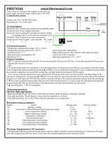
Figure 1.1 Fuzzy PID System Block
PID + FUZZY CONTROL
The function of Fuzzy Logic is to adjust PID parameters internally in order to make
PID + FUZZY CONTROL
Smarter Logic causes the following:
If temperature difference is large and temperature rate is large, then delta MV is large.
If temperature difference is large and temperature rate is small, then delta MV is small.
Warm Up
Load Disturbance
PID tuned controller
PID+Fuzzy control
Set
point
Temperature
Time
Figure 1.2 Fuzzy PID Enhances Control Stability

3
1-2 Ordering Code
A
ccessories
CT94-1 = 0 - 50 Amp. AC Current T
ransformer
OM95-3 = Isolated 4 - 20 mA / 0 - 20 mA Analog Output Module
OM95-4 = Isolated 1 - 5V / 0 - 5V Analog Output Module
OM95-5 = Isolated 0 - 10V Analog Output Module
OM94-6 = Isolated 1A / 240V
AC Triac Output Module ( SSR )
DC94-1 = Isolated 20V / 25mA DC Output P
ower Supply
DC94-2 = Isolated 12V / 40mA DC Output P
ower Supply
DC94-3 = Isolated 5V / 80mA DC Output P
ower Supply
CM94-1 = Isolated RS
-485 Interface Module
CM94-2 = Isolated RS
-232 Interface Module
CM94-3 = Isolated 4 - 20 mA / 0 - 20 mA R
etransmission Module
CM94-4 = Isolated 1 - 5V / 0 - 5V R
etransmission Module
CM94-5 = Isolated 0 - 10V R
etransmission Module
CC94-1 = RS
-232 Interface Cable (2M)
UM34001A = ETR-3400 User's Manual
4: 90 - 264 VAC, 50/60 HZ
5: 11 - 26 VAC or VDC
4: 90 - 264 VAC, 50/60 HZ
5: 11 - 26 VAC or VDC
0: None
1: RS-485
2: RS-232
3: Retransmit 4-20mA/0-20mA
4: Retransmit 1 - 5V / 0 - 5V
5: Retransmit 0 - 10V
0: None
1: RS-485
2: RS-232
3: Retransmit 4-20mA/0-20mA
4: Retransmit 1 - 5V / 0 - 5V
5: Retransmit 0 - 10V
1: Standard Input
Input 1 - Universal Input
Thermocouple: J, K, T, E, B,
R, S, N, L
RTD: PT100 DIN, PT100 JIS
Current: 4 - 20mA, 0 - 20 mA.
Voltage: 0 - 1V, 0 - 5V, 1 - 5V,
0 - 10V
Input 2 -
CT: 0 - 50 Amp. AC Current
Transformer
Voltage Input: 0 - 1V, 0 - 5V,
1 - 5V, 0 - 10V.
Event Input ( EI )
1: Standard Input
Input 1 - Universal Input
Thermocouple: J, K, T, E, B,
R, S, N, L
RTD: PT100 DIN, PT100 JIS
Current: 4 - 20mA, 0 - 20 mA.
Voltage: 0 - 1V, 0 - 5V, 1 - 5V,
0 - 10V
Input 2 -
CT: 0 - 50 Amp. AC Current
Transformer
Voltage Input: 0 - 1V, 0 - 5V,
1 - 5V, 0 - 10V.
Event Input ( EI )
1: Relay rated 2A/240VAC
2: Pulsed voltage to
drive SSR, 5V/30mA
3: Isolated
4 - 20mA / 0 - 20mA
4: Isolated 1 - 5V / 0 - 5V
5: Isolated 0 - 10V
6: Triac Output
1A / 240VAC,SSR
C: SSR Drive 14V/30mA
1: Relay rated 2A/240VAC
2: Pulsed voltage to
drive SSR, 5V/30mA
3: Isolated
4 - 20mA / 0 - 20mA
4: Isolated 1 - 5V / 0 - 5V
5: Isolated 0 - 10V
6: Triac Output
1A / 240VAC,SSR
C: SSR Drive 14V/30mA
1: 5V Logic
Output
1: 5V Logic
Output
1 2
3 4
5
6
0: None
1: Form A Relay 2A/240VAC
2: Pulsed voltage to
drive SSR, 5V / 30mA
3: Isolated 4 - 20mA / 0 - 20mA
4: Isolated 1 - 5V / 0 - 5V
5: Isolated 0 - 10V
6: Triac Output, 1A / 240VAC, SSR
7: Isolated 20V / 25mA DC
Output Power Supply
8: Isolated 12V / 40 mA DC
Output Power Supply
9: Isolated 5V / 80mA DC
Output Power Supply
C: SSR Drive 14V/30mA
ETR-3400
Standard Model:
ETR
-3400-411111
90 - 264 operating voltage
Input: Standard Input
Output 1: Relay
Output 2: Relay
Alarm 1: 5V Logic Output
RS- 485 Communication Interface
Standard Model:
ETR
-3400-411111
90 - 264 operating voltage
Input: Standard Input
Output 1: Relay
Output 2: Relay
Alarm 1: 5V Logic Output
RS- 485 Communication Interface
SNA10B = Smart Network Adaptor for ETR
-Net
Software, Converts 247 channels
of RS-485 or RS-422 to RS-232
Network
SNA10B = Smart Network Adaptor for ETR
-Net
Software, Converts 247 channels
of RS-485 or RS-422 to RS-232
Network
P10A = Hand-held Programmer for ETR
Series Controller
P10A = Hand-held Programmer for ETR
Series Controller
SNA10A = Smart Network Adaptor for Third
Party Software, Converts 247
channels of RS-485 or RS-422 to
RS-232 Network
SNA10A = Smart Network Adaptor for Third
Party Software, Converts 247
channels of RS-485 or RS-422 to
RS-232 Network
Example
Related Products
Range set by front keyboard
Alternative between RS-232 and Input 2
Need to order an accessory CT94-1 if
Heater Break detection is required.
Range set by front keyboard
Alternative between RS-232 and Input 2
Need to order an accessory CT94-1 if
Heater Break detection is required.
******
******
****
****
****
*
**
**
**
**
**
**
**

4
1-3 Programming Port and DIP Switch
Figure 1.3 Access Hole Overview
Front
Panel
Rear
T
erminal
Access Hole
1
PIDNO
432
The programming port connects to the
P11A hand-held programmer for automatic
programming, this also connects to an ATE
system for automatic calibration and testing.
Table 1.1 DIP Switch Configuration
TC, RTD, mV
0-1V, 0-5V, 1-5V, 0-10V
0-20 mA, 4-20 mA
Input 1
Select
All parameters are Unlocked
Only SP1, SEL1 SEL5 are unlocked
Only SP1is unlocked
All Parameters are locked
Lockout
12
34
DIP Switch
:ON :OFF
Factory Default Setting
*
The mini jumper ( programming port ) is used for off-line automatic setup and testing procedures only. Don’t at-
tempt to make any connection to these jumpers when the unit is powered on.
When the unit leaves the factory, the DIP switch is set so that TC & RTD are selected. Lockout function is used to
disable the adjustment of parameters as well as operation of the unit prior to setup being performe
*SEL1- SEL5 represent those parameters which are selected by using SEL1, SEL2,...SEL5 parameters contained
in Setup menu. Parameters that were selected are then allocated to the chosen SEL position.

5
1-4 Keys and Displays
The unit is programmed by using three keys on the front panel. The available key functions are listed in following table.
Pressand releasequickly to increase thevalue of parameter.
Pressand holdtoaccelerateincrementspeed.
Pressand releasequickly to decreasethe value of parameter.
Pressand holdtoaccelerate decrement speed.
Select the parameter in adirect sequence.
Allow access to more parametersonuser menu, also used to Enter manual
mode, auto-tune mode,defaultsetting modeand to save calibrationdata
duringcalibrationprocedure.
Select the parameter in a reverse sequenceduring menu scrolling.
Select the operation Mode in sequence.
Reset the frontdisplay to anormal display mode from anywhere within the
parameterbank. This also exits theauto-tuneand manual control
operation while quitting thesleep mode.
The controllerentersthe sleep modeifthe sleep function ( SLEP)is enabled
( selectYES ).
By entering correct security codeto allow execution of engineering programs.
This function is used onlyatthe factory to manage thediagnostic reports.
The user should never attempt to operate this function.
Press
for at least3seconds
Press
for at least6seconds
Press
Press
Press
Press
Press
for at least3seconds
Up Key
Down Key
Scroll Key
EnterKey
Start Record Key
Reverse Scroll Key
ModeKey
Reset Key
Sleep Key
Factory Key
NOITPIRCSEDNOITCNUFSYEKHCUOT
Reset historicalvaluesofPVHI and PVLO andstart to recordthe peak process
value.
Table 1.2 Keypad Operation
Alarm 1
Indicator
Output
2
Indicator
3 Silicone Rubber Buttons
for ease of control setup
and set point adjustment.
Output 1
Indicator
Figure 1.4 Front Panel Layout
4-digit Display
to display process value,
set point value, menu symbol,
parameter value, control output
value and error code etc.
O1
O2
A1
F
ETR-3400
: These characters are displayed with symbols
A
E
I
N
S
X
B
F
J
O
T
Y
C
G
K
P
U
Z
c
H
L
Q
V
?
Dh
M
R
W
=
Table 1.3 Character Legend
For a number with decimal point the
display will be shifted one digit right:
-19999 will be displa yed by:
45536 will be displaye d by:
-9999 will be displaye d by:
-199.99 will be displayed by -199.9
4553.6 will be displayed by 4553
For a number without decimal point
the display will be divided into two
alternating phases:
How to display a 5-digit number?

6
Power On
All segments of display and
indicators are left off for 0.5
second.
All segments of display and
indicators are lit for 2 seconds.
Display Date Code and Serial
number for 2.5 seconds.
Each display stays for 1.25 seconds
Display used hours for 2.5
seconds.
The 6-digit number of hour is indicated
by two successive displays and each
one stays on for 1.25 seconds.
The left diagram shows that the
unit has been used for 23456.2
hours since production.
Figure 1.5 Display Sequence o
f
Initial Power-up
Display program code of the
product for 2.5 seconds.
Each display stays for 1.25 seconds
The left diagram shows program
no. 0 ( for ETR-3400 ) with version
35.
Program No.
Program version
Year (1999)
Month (December)
Date (31st)
Date Code
The left diagram shows Year 1998,
Month July ( 7 ), Date 31'st and
Serial number 192. This means that
the product is the 192'nd unit
produced on July 31'st, 1998.
Note that the month code stands for
stands for and
stands for.
A
October, BNovember C
December
O1
O2
A1
F
ETR-3400
O1
O2
A1
F
ETR-3400
O1
O2
A1
F
ETR-3400
O1
O2
A1
F
ETR-3400
O1
O2
A1
F
ETR-3400
F
ETR-3400
O1
O2
A1
F
ETR-3400
O1
O2
A1
F
ETR-3400
Program Code

7
PV Value
SV Value
User
Menu
Setup
Menu
Hand (Manual)
Control
Mode
Auto-tuning
Mode
Display
Mode
Entering these modes will break the control loop and
change some of the previous setting data. Make sure that
settings are properly backed up prior to initiating if they
are to be used again.
RAMP
A2DV
A2SP
A1DV
A1SP
TIME
PB1
SHIF
CPB
REFC
TD1
OFST
TI1
TD2
TI2
PB2
SP2
PL2
PL1
A2HY
A1HY
O1HY
SEL1
SEL5
SEL4
SEL3
SEL2
PVHI
PVLO
PV1
PV2
PB
TD
TI
DV
CJCT
PVR
PVRH
PVRL
H
C
AOHI
IN1L
SP1H
SP2F
AOLO
DP1
SP1L
AOFN
IN1U
SPMD
STOP
IN1
IN1H
IN2H
SLEP
PARI
IN2L
SELF
FILT
PVMD
EIFN
DATA
DP2
BAUD
IN2U
ADDR
IN2
PROT
COMM
FUNC
O1TY
O2TY
A1MD
A2FT
OUT1
OUT2
A1FN
A2MD
O1FT
O2FT
A2FN
CYC1
CYC2
A1FT
SEL1
DISF
SEL2
SEL5
SEL4
SEL3
H
C
V2G
MA1G
SR1
REF1
CJG
CJTL
V1G
ADG
AD0
Calibration
Mode
for3seconds
for 3
seconds
Default
Setting
Mode
FILE
To execute the
default setting
program
for
3 seconds
Pressfor 3 secondsto enter
the auto-tuning mode
The flow chart shows a complete listing of all parameters.
For actual application the number of available parameters
depends on setup conditions, and should be less
than that shown in the flow chart. See Appendix A for the
existence conditions of each parameter.
*1:
You can select at most 5 parameters to put in front of the
user menu by using SEL1 to SEL5 located at the end of
the setup process
Set DISF (display format) value in the setup menu to
chan
g
e between PV (Process Value) and SV (Setpoint Value)
*2:
*3:
*1
*1
*3
or
*2
Display Return
The menu will return to
displaying the selected
PV or SV after 2 min.
if no entry is made
except, when in the
However, the menu can
return to the selected PV
or SV display at any time
by pressing and .
Display Mode or in the
Manual Mode.
DB
1-5 Menu Overview

8
1-6 System Modes
The controller performs a closed loop control mode under its normal control mode operation. The controller will
maintain its normal control mode when you are operating the user menu, setup menu or display mode, reloading
default values or applying an event input signal. Under certain conditions the normal control mode will transfer
to an Exception Mode. The exception modes include : Sleep Mode, Manual Mode, Failure Mode, Calibration
Mode and Auto Tuning Mode. All these modes perform in an open loop control except the auto-tuning mode
which performs ON-OFF plus PID close loop control. The mode transfer is governed by the priority as shown in
Figure 1.6.
Figure 1.6 System Mode Priority
? Mode
Failure Mode?
No
Yes
Request
Normal
Control
Mode
Request
Auto-tuning
Mode
Request
Calibration
Mode
Priority
High
Low
The calibration mode, auto-tuning mode and normal control mode are in the same priority level.
Yes
Yes
No
No
Sleep Mode?
Manual Mode?
System Modes
Sleep Mode: See Section 4-11
Manual Mode: See Section 3-23
Failure Mode: See Section 3-17
Calibration Mode: See Chapter 6
Auto-tuning Mode: See Section 3-20
Normal Control Mode: See Section 3-24, 3-26, 4-1

9
1-7 Parameter Descriptions
Table 1.4 Parameter Description (1 of 7)
Parameter
Description
Range
Default
Value
Contained
in
Basic
Function
Parameter
Notation
Display
Format
SP1
Set point1
SP1L SP1H
100.0C
(212.0 F)
TIME
0 6553.5 minutes 0.0
DwellTime
A1SP
100.0C
(212.0 F)
Alarm 1Set point
A1DV
Alarm 1 DeviationValue
-200.0 C
(-360.0 F)
10.0C
(18.0 F)
A2SP
Alarm 2Set point
100.0C
(212.0 F)
A2DV
Alarm 2 DeviationValue
-200.0 C
(-360.0 F)
10.0C
(18.0 F)
RAMP
Ramp Rate
0.00
OFST
REFC
SHIF
PB1
TI1User
Menu
Setup
Menu
TD1
Offset Value forPcontrol
PV1 Shift (offset) Value
Proportional Band 1Value
IntegralTime 1Value
DerivativeTime 1Value
0
0
0
0
0
25.0
100
CPB
Cooling Proportional Band
Value
1
100
25.0
-200.0 C
(-360.0 F)
10.0C
(18.0 F)
0.0
Reference Constantfor
Specific Function
2
Low:
Low:
Low:
Low:
Low:
Low:
Low:
Low:
Low:
Low:
Low:
Low:
Low:
Low:
Low:
Low:
Low:
Low:
High:
High:
Low:
200.0 C
( 360.0F)
500.0C
(900.0 F)
100.0 %
60
200.0 C
( 360.0F)
High:
High:
High:
High:
High:
SP2
PB2
TI2
TD2
O1HY
A1HY
A2HY
PL1
PL2
COMM
PROT
Set point2
Proportional Band 2Value
IntegralTime 2Value
DerivativeTime 2Value
Output1ON-OFFControl
Hysteresis
Hysteresis ControlofAlarm 1
Hysteresis ControlofAlarm 2
Output1Power Limit
Output2Power Limit
Function Complexity Level
Communication Interface
Type
COMM Protocol Selection
0
Low:
0
0
0
0.1
0.1
0.1
0
100
100
100
25.0
37.8 C
(100.0 F)
1000 sec
360.0 sec
255 %
500.0C
(900.0 F)
200.0 C
( 360.0F)
High:
High:
High:
High:
High:
High:
1000 sec
500.0C
(900.0 F)
High:
High:
High:
High:
High:
High:
High:
100%
100%
360.0 sec
55.6C
( 100.0F)
10.0C
(18.0F)
10.0C
(18.0F)
10.0C
(18.0F)
0.1
0.1
0.1
FUNC
0
Basic Function Mode
:
Full Function Mode
:
1
0
:
No communication function
:
1
RS-485 interface
2
:
RS-232 interface
:
3
4-20 mA analog retransmission
output
4
:
0-20 mA analog retransmission
output
:
5
0-1V analog retransmission
output
6
:
0-5V analog retransmission
output
:
7
1-5V analog retransmission
output
8
:
:
0-10V analog retransmission
output
1
1
0
SeeTable 1.5, 1.6
SeeTable 1.5, 1.7
SeeTable 1.5, 1.8
0
Modbus protocol RTU mode
DB
Heating-CoolingDead Band
NegativeValue= Overlap
-36.0
0
Low:
36.0%
High:

10
:
:
:
:
:
:
:
:
:
:
:
BAUD
DATA
PARI
STOP
AOFN
Baud Rateof Digital COMM
DataBit countof Digital
COMM
ParityBit of Digital COMM
Stop Bit Countof Digital
COMM
Analog Output Function
5
1
0
0
0
1
(0)
AOLO
AOHI
Analog OutputLow Scale
Value
Analog Output High Scale
Value
-19999
-19999
45536
45536
ADDR
Address Assignmentof Digital
COMM
Low:
Low:
Low:
High:
High:
High:
5521
0
0
1
1
2
2
3
3
4
4
5
5
6
6
7
8
9
0.3Kbits/s baudrate
0.6Kbits/s baudrate
1.2Kbits/s baudrate
2.4Kbits/s baudrate
4.8Kbits/s baudrate
9.6Kbits/s baudrate
14.4Kbits/s baudrate
19.2Kbits/s baudrate
28.8Kbits/s baudrate
38.4Kbits/s baudrate
0
7 data bits
:
:
:
:
:
:
:
:
:
:
:
:
:
18data bits
0
1
0
2
1
Even parity
Odd parity
No parity bit
One stop bit
Two stop bits
0
:
RetransmitIN1 process value
1
:
RetransmitIN2 process value
4
:
Retransmitset point value
5
:
Retransmit output1manipulation
value
6
:
Retransmit output2manipulation
value
2
:
RetransmitIN1 IN2 difference
process value
3
:
RetransmitIN2 IN1 difference
process value
7
:
Retransmit deviation(PV-SV)
Value
0C
(32.0F)
100.0C
(212.0F)
IN1
IN1 SensorType Selection
Ttypethermocouple
Etypethermocouple
Btypethermocouple
Rtypethermocouple
Stypethermocouple
Jtypethermocouple
Ktypethermocouple
Table 1.4 Parameter Description (continued 2 of 7)
Setup
Menu
Parameter
Description
Range
Default
Value
Contained
in
Basic
Function
Parameter
Notation
Display
Format

11
Low:
Low:
High:
High:
IN2U
DP2
IN2L
IN2H
IN2 Unit Selection
IN2 Decimal Point Selection
IN2 Low Scale Value
IN2 High Scale Value
-19999
-19999
45536
45536
SameasIN1U
Sameas DP1
0
1000
2
1
IN1U
IN1
DP1
IN1L
IN1H
IN1 Unit Selection
IN1 Sensor Type Selection
IN1 Decimal Point Selection
IN1 Low Scale Value
IN1 High Scale Value
-19999
-19999
45536
45536
7
13
4
8
14
5
9
0
15
6
10
1
16
7
20
11
17
12
0
0
1
1
2
2
3
N type thermocouple
L type thermocouple
PT 100 ohms DIN curve
PT 100 ohms JIS curve
4-20 mA linear current input
0-20 mA linear current input
0-1V linear Voltage input
0-5V linear Voltage input
1-5V linear Voltage input
0-10V linear Voltage input
Special defined sensor curve
Low:
Low:
High:
High:
0
1000
1
0
(1)
1
(0)
IN2
IN2 Signal Type Selection
1
IN2 no function
Current transformer input
0-1V linear voltage input
0-5V linear voltage input
1-5V linear voltage input
0-10V linear voltage input
:
:
:
:
:
:
:
:
:
:
:
:
:
:
:
:
:
:
:
:
:
:
:
:
:
Degree C unit
Degree F unit
Process unit
No decimal point
1 decimal digit
2 decimal digits
3 decimal digits
Output 1 Function
0
0
OUT1
O1TY
0
1
Reverse (heating ) control action
Direct (cooling) control action
:
:
0
1
2
3
Relay output
Solid state relay drive output
Solid state relay output
4-20 mA current module
:
:
:
:
Output 1 Signal Type
Table 1.4 Parameter Description (continued 3 of 7)
Setup
Menu
Perform Event input function
Parameter
Description
Range
Default
Value
Contained
in
Basic
Function
Parameter
Notation
Display
Format

12
4
5
6
7
0-20 mA current module
0-1V voltage module
0-5V voltage module
1-5V voltage module
8
0-10V voltage module
:
:
:
:
:
CYC1
O1TY
Output 1 CycleTime
100.0 sec 18.0
0
0.1
Low:
High:
O1FT
Output 1 Failure Transfer
Mode
SelectBPLS(bumpless transfer)or 0.0 ~ 100.0
%to continue output1control function as the unit
fails, power starts or manual mode starts.
SelectBPLS(bumpless transfer)or 0.0 ~ 100.0
%to continue output2control function as the unit
fails, power starts or manual mode starts.
BPLS
Output 2 Function
OUT2
2
0
1
2
:PID cooling control
:Perform alarm2function
: Output2no function
3
:DC power supply module
installed
O2TY
CYC2
O2FT
Output 2 Signal Type
Output 2 Cycle Time
Output 2 Failure Transfer
Mode
100.0 sec
BPLS
18.0
0
0.1
Sameas O1TY
Low:
High:
A1FN
Alarm1Function
2
6
IN1 process value high alarm
:
9
IN2 process value low alarm
:
0
No alarm function
:
4
Deviation band outof band alarm
:
1
Dwell timer action
:
5
Deviation band in band alarm
:
8 IN2 process value high alarm
:
3
Deviation low alarm
:
2
Deviation high alarm
:
11
IN1or IN2 process value low
alarm
:
7IN1 process value low alarm
:
10
IN1or IN2 process value high
alarm
:
12
IN1 IN2 difference process value
high alarm
:
13
IN1 IN2 difference process value
low alarm
:
:
:
14 Loop break alarm
15 Sensor break or A-D fails
:
:
:
:
1
2
3
0
Normal alarm action
Latching alarm action
Hold alarm action
Latching & actionHold
A1MD
Alarm1Operation Mode
0
Table 1-4 Parameter Description (continued 4 of 7)
Setup
Menu
Output 1 Signal Type
Parameter
Description
Range
Default
Value
Contained
in
Basic
Function
Parameter
Notation
Display
Format

13
:
:
SELF
SelfTuning Function
Selection
:
:
0
1
Self tune function disabled
Self tune function enabled
SLEP
Sleep mode Function
Selection
0
Sleep mode function disabled
Sleep mode function enabled
1
0
0
:
:
A1FT
A2FT
A2FN
Alarm 1 FailureTransfer
Mode
Alarm 2 FailureTransfer
Mode
Alarm 2 Function
1
2
0
1
Alarm output OFF as unit fails
Alarm outputONas unit fails
Same as A1FN
Same as A1MD
Same as A1FT
A2MD
Alarm 2 Operation Mode
0
1
1
EIFN
Event Input Function
3
4
SP2,PB2,TI2, TD2 activated to
replace SP1,PB1, TI1, TD1
Reset alarm 1 output
9
10
Disable Output1&Output2
LockAll Parameters
0
Event input no function
:
1SP2 activated to replace SP1
:
2
PB2, TI2, TD2 activatedtoreplace
PB1, TI1, TD1
:
:
:
5
Reset alarm 2 output
:
6
Reset alarm1&alarm 2
:
7
Disable Output1
:
8
Disable Output2
:
:
:
PVMD PV Mode Selection
:
:
0
1
Use PV1 as process value
Use PV2 as process value
:
2
Use PV1 PV2 (difference) as
process value
:
3
Use PV2 PV1 (difference) as
process value
0
0
1
2
3
4
0 second time constant
0.2 second time constant
0.5 second time constant
1 second time constant
2 seconds time constant
5 seconds time constant
10 seconds time constant
20 seconds time constant
30 seconds time constant
60 seconds time constant
5
6
7
8
9
:
:
:
:
:
:
:
:
:
:
FILT
Filter DampingTime
ConstantofPV
2
Table 1-4 Parameter Description (continued 5 of 7)
Setup
Menu
Parameter
Description
Range
Default
Value
Contained
in
Basic
Function
Parameter
Notation
Display
Format

14
:
:
SP2F
DISF
Formatof set point2Value
Display Format
0
1
set point 2(SP2) is an actual value
set point 2(SP2) isadeviation
value
0
:
:
:
:
:
:
SPMD Set point Mode Selection
0
1
2
3
4
5
Use SP1 or SP2 (depends on EIFN)
as setpoint
Use minute ramp rate as set point
Use hour ramp rateas set point
Use IN1 processvalueas set point
Use IN2 processvalueas set point
Selected for pump control
SEL1 Select 1'st Parameter
0
:
:
:
:
:
:
:
:
:
:
:
:
:
:
:
:
:
:
:
:
16
17
18
ParameterPB2 put ahead
Parameter TI2 put ahead
ParameterTD2 put ahead
0
0
1
1
2
3
4
5
6
No parameter put ahead
Display PV value
Display SV value
Parameter TIME put ahead
ParameterA1SP put ahead
ParameterA1DV put ahead
ParameterA2SP put ahead
ParameterA2DV put ahead
ParameterRAMP put ahead
ParameterOFST put ahead
ParameterREFC put ahead
ParameterSHIF put ahead
ParameterPB1 put ahead
Parameter TI1 put ahead
ParameterTD1 put ahead
ParameterCPB put ahead
ParameterSP2 put ahead
7
8
9
10
11
12
13
14
15
ParameterDB put ahead
0
SEL2
SEL3
SEL4
Same as SEL1
Same as SEL1
Same as SEL1
0
0
0
Low:
Low:
High:
High:
SP1L
SP1H
SP1Low Scale Value
SP1High Scale Value
-19999
-19999
45536
45536
0C
(32.0F)
1000.0 C
(1832.0 F)
Table 1-4 Parameter Description (continued 6 of 7)
Select 2'ndParameter
Select 3'rd Parameter
Select 4'th Parameter
Select 5'th Parameter
SEL5
Same as SEL1
0
AD0
ADG
V1G
AtoDZero Calibration
Coefficient
AtoDGain Calibration
Coefficient
Voltage Input1Gain
Calibration Coefficient
-360 360
-199.9 199.9
-199.9 199.9
Low:
Low:
Low:
High:
High:
High:
Low:
High:
CJTL
ColdJunction Low
Temperature Calibration
Coefficient
-5.00C 40.00 C
Calibration
Mode
Menu
Setup
Menu
:
Parameter
Description
Range
Default
Value
Contained
in
Basic
Function
Parameter
Notation
Display
Format

15
Low:
High:
V2G
Voltage Input2Gain
Calibration Coefficient
-199.9 199.9
Low:
Low:
Low:
Low:
High:
High:
High:
High:
CJG
REF1
SR1
MA1G
Cold Junction Gain
Calibration Coefficient
Reference Voltage 1
Calibration Coefficientfor
RTD1
Serial Resistance 1
Calibration Coefficientfor
RTD1
mA Input1Gain Calibration
Coefficient
-199.9
-199.9
-199.9
-199.9
199.9
199.9
199.9
199.9
Table 1.4 Parameter Description (continued 7 of 7)
Calibration
Mode
Menu
Display
Mode
Menu
Low:
Low:
High:
High:
PVHI
PVLO
Historical Maximum Valueof
PV
Historical Minimum Valueof
PV
-19999
-19999
45536
45536
Low:
Low:
High:
High:
MV1
MV2
Current Output 1Value
Current Output 2Value
0
0
100.00 %
100.00 %
Low:
Low:
Low:
Low:
Low:
Low:
Low:
Low:
Low:
Low:
High:
High:
High:
High:
High:
High:
High:
High:
High:
High:
DV
PV1
PV2
PB
TI
TD
CJCT
PVR
PVRH
PVRL
-12600
-19999
-19999
12600
45536
45536
0
0
Current Deviation(PV-SV)
Value
IN1 Process Value
IN2 Process Value
Current Proportional Band
Value
Current Integral Time Value
Current Derivative Time
Value
ColdJunction Compensation
Temperature
Current Process Rate Value
Maximum Process Rate Value
Minimum Process Rate Value
0
4000 sec
1440 sec
500.0 C
(900.0 F)
-40.00C
-16383
-16383
-16383
90.00C
16383
16383
16383
Parameter
Description
Range
Default
Value
Contained
in
Basic
Function
Parameter
Notation
Display
Format

16
Table 1.5 Input (IN1 of IN2) Range
Range
of A1SP
same as range of
Range
of SP2
same as range of
Range of A2SP
sameas range of
If A1FN =
If PVMD =
If A2FN=
PV1.H, PV1.L
PV1
PV1.H, PV1.L
IN1
IN1
IN1
PV2.H,PV2.L
PV2
PV2.H,PV2.L
IN2
IN2
IN2
P1.2.H, P1.2.L
D1.2.H, D1.2.L
P1.2.H, P1.2.L
D1.2.H, D1.2.L
IN1, IN2
IN1, IN2
IN1,IN2
InputType
Input Type
J_TC
N_TC
K_TC
L_TC
T_TC
PT.DN
E_TC
PT.JS
B_TC
CT
R_TC
Linear (V, mA)
or SPEC
S_TC
Range Low
Range Low
Range High
Range High
-120C
(-184 F)
1000 C
(1832 F)
1300 C
(2372 F)
-200C
(-328 F)
-200 C
(-328 F)
-200 C
(-328 F)
1370C
(2498 F)
-250 C
(-418 F)
-250 C
(-418 F)
-210 C
(-346 F)
400 C
(752 F)
700C
(1292 F)
-100 C
(-148 F)
900 C
(1652F)
900 C
(1652 F)
600C
(1112F)
0C
(32 F)
0C
(32 F)
0C
(32F)
1820 C
(3308F)
1767.8C
(3214F)
1767.8 C
(3214F)
0 Amp
90 Amp
-19999
45536
P1 2, P2 1
Exception:If any of A1SP
, A2SP or SP2 is configured with respect to
CT input, its adjustment range is unlimited.
Table 1.6 Range Determination for A1SP
Table 1.7 Range Determination for A2SP
Table 1.8 Range Determination for SP2
/